1. 서 론
.
,
. 20
.
.
,
. ,
3
,
화력발전소 주배관 차원 변위측정시스템 개발 3
송기욱*․현중섭*․하정수*․조선영**
Development of 3-D. Displacement Measurement System for Critical Pipe of Fossil Power Plant
G.W. Song, J.S. Hyun, J.S. Ha, and S.Y. Cho
Key Words:
3-D Displacement Measurement System(3차원 변위측정시스템), LVDT Type식 센서 고온 증기배관
Sensor(LVDT ), High Temperature Steam Pipe( ), Fossil Power 화력발전소
Plant( ).
Abstract
Most domestic fossil power plant have exceeded 100,000 hours of operation with the severe operating condition. Among the critical components of fossil power plant, high temperature steam pipe system have had a many problems and damage from unstable displacement behavior because of frequent start up and shut down. In order to prevent the serious damage and failure of the critical pipe system in fossil power plant, 3-dimensional displacement measurement system were developed for the on-line monitoring system. 3-D Measurement system was developed with using the LVDT type sensor and rotary encoder type sensor, this system was installed and operated on the real power plant successfully. In the future time, network system of on-line diagnosis for critical pipe will be designed.
*
한국전력공사 전력연구원 발전연구실**
(주) K.R. 정밀.
2.
2-1
3
(sensor) .
LVDT ,
(Rotary Encoder) .
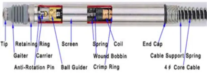
LVDT
, , , ,
Fig. 1 Core
Coil Coil
. Core (Ve)
VA=VB V0=0 . Core
VA VB
,
V0 .
, (Ve)
Core VA VB
.
Fig. 1. Displacement LVDT Sensor
,
.
disk shaft ,
,
.
, LVDT
, LVDT
1
3
.
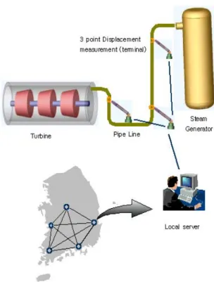
Fig. 2 3
.
3 ( ,
, )
.
.
.
Fig. 2 Scheme Diagram
동점 A
거리 r
(LVDT) 회전각, θ φ, (Encoder 1, 2)
.
Encoder LVDT . ,
Moment Free ,
Encoder , ,
LVDT , r .
2-2 Mock-up
3
Mock-up
Fig. 3 .
, Free
.
LVDT rod 1
3
.
3
, x,
y, z 3 .
Fig. 3 3
2-3. Mock-up 3
,
4 .
3 . Table 1
-0.09
+0.15% 0.15%
.
Table 1
3.
3 LVDT Encoder
.
, analogue digital
local server data ,
.
3-1.
3
analogue 2 Encoder Digital
Output 20 bit LVDT Analog Output 1CH
(0~10V) , analogue
local server .
. TCP/IP , RS232 & RS 485 ,
, , . , TIP/IP RS232 & RS485
data
. data
AD converter
terminal .
,
PC RS-485
DC ±24V .
3-2. 3
, Fig. 4 . Program tool NI
LabVIEW ,
. part
,
. part
monitoring
(a)
(b) Fig. 4 3
4.
3
Mock-up 3
. Mock-up
“A" 2 (Main steam line)
(MS-2 Hanger ) .
(Hanger) MS-2
Lug , 2003. 4. 22 ,
2003. 8. 12 110 .
4-1. Mock-up
3
(Deadweight)
(Hanger) MS-2 (Fig.
5) .
,
Fig.
6 Clamp . Clamp
2 Clamp
,
Rod . Clamp
200mm
.
Fig. 5 "A" (MS-2)
Fig. 6 MS-2 Clamp
4-1-2.
1) 3 ,
. 3
Fixture .
,
, .
, 3
Truss .
.
Fig. 7 3
MS-2 Clamp
.
Fig. 7
2) 3
, 3 Fixture
Clamp
(OD100×10t) 3
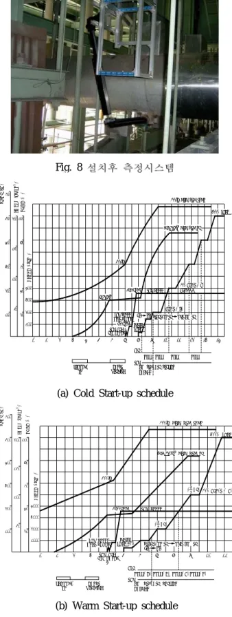
Fig. 8 .
4-2.
4-2-1.
Fig. 9 Cold Warm Start
“A" 2 .
.
Fig. 8
(a) Cold Start-up schedule
1 2 3 4 5 6 7 8 9 10 11 12
4000 3000 2000 1000 100 200 300 400 500 600
200
150
100
50 100
20 40 60 80
S P E E D ( r p m )
L O A D ( % )
P R E S S ( k g /c m )
T e m p ( °C )
2500°C MAIN STM TEMP
169 kg/cm MAIN STM PR 2
60kg/cm 2 300°C
3600RPM TBN SPEED
800RPM
100% LOAD
TBN BRG RUB CHECK
LOW SPEED HEAT SHOCK
INITIAL LOAD
START-UP TR UNIT AUX TR FA PA
BLR TBN
PULV HTR SERVICE AUX STM CHANGE
VACUUM- CHEST
UP WARMING
0 13 14
50% BFP-T (# B) BFPM 정지
BFP-T (# A)
PULV PULV PULV
(b) Warm Start-up schedule
1 2 3
4
5 6 7 8 9 10 11
4000 3000 2000 1000 100 200 300 400 500 600
200
150
100
50 100
20 40 60 80
S P E E D ( r p m )
L O A D ( % )
P R E S S ( k g /c m )
T e m p ( °C )
2500°C MAIN STM TEMP
169 kg/cm MAIN STM PR
2300°C
3600RPM TBN SPEED
100% LOAD
TBN BRG RUB CHECK LOW SPEED HEAT SHOCK
INITIAL
LOAD START-UP TR UNIT AUX TR
FA PA
BLR TBN
PULV(#C) PULV(#D) PULV(#B) PULV(#E) HTR SERVICE AUX STM CHANGE
VACUUM- CHEST
UP WARMING
0
( HR)
1250% BFP-T (# B) ( HR)
21( HR)21