유연/신축성 전자패키징 용 폴리머 재료의 기계적 물성 측정 기술 리뷰
김철규·이태익·김택수† 한국과학기술원 기계공학과
Measurement Technologies of Mechanical Properties of Polymers used for Flexible and Stretchable Electronic Packaging
Cheolgyu Kim, Tae-Ik Lee and Taek-Soo Kim†
Department of Mechanical Engineering, Korea Advanced Institute of Science and Technology (KAIST), 291, Daehak-ro Yuseong-gu, Daejeon 34141, Korea
(Received May 25, 2016: Corrected June 3, 2016: Accepted June 7, 2016)
Abstract: This paper presents an overview of selected advanced measurement technologies for the mechanical properties of polymers used for flexible and stretchable electronic packaging. Over the years, a variety of flexible and stretchable electronics have been developed due to their potential applications for next generation IT industry. To achieve more flexible and wearable devices for practical applications, the usage of polymeric components has been increased significantly.
Therefore, accurate measurement of mechanical properties of the polymers is necessary in order to design mechanically reliable devices. However, the measurement has been challenging due to the soft nature and thin applications of polymers.
Here, we describe novel measurement technologies of mechanical properties of polymers for flexible and stretchable electronics.
Keywords: Flexible electronics, Stretchable electronics, Polymer, Mechanical properties, Measurement technology
1. 서 론
최근의 IT 업계의 트렌드는 기존의 전자 패키징에 들 어가는 단단한 기판의 제품에서 제품의 모양을 변형할 수 있는 플렉서블, 스트레처블, 웨어러블한 제품으로 변화하 고 있다. 안경 모양으로 사용 가능한 웨어러블 컴퓨터인 구글 글래스를 비롯하여 사용자의 위치에 맞추어 곡률을 변화시킬 수 있는 가변형 TV 등 많은 제품들이 차세대 기술로 각광받고 있다. 최근 다양한 재료와 마이크로/나 노 구조물 제작기술을 이용한 유연성을 가지는 새로운 트 랜지스터,1,2) 전자종이,3,4) 메모리,5,6) LED,7-9) 센서,10,11) 태
양전지,12,13) 배터리14,15) 등에 대한 다양한 보고들이 나타
나고 있다. Fig. 1에서는 차세대 유연 전자소자의 응용 가 능 분야를 나타내었다.
이를 구현하기 위해서는 제품에 들어가는 소자의 구조 적 소형화, 박형화, 경량화, 유연화가 필수적이다. 소재적 관점에서는 다양한 모양으로 변형이 가능해야 하며 휘어 지고 늘어나는 상황에서도 성능의 저하가 없는 디바이스 를 구현하는 전자패키징 기술의 개발되어야 한다. 따라
서 유연 소자의 기술 개발을 위해서는 다양한 공정에 부 합하는 유연 기판이 필요하다.
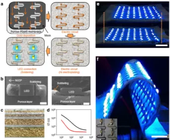
폴리머는 가공의 용이성, 경량성, 반도체 공정과의 적 합성, 또 재료의 변형 가능한 범위가 크다는 점에서 유연 기판에 쓰일 소재로 주목 받고 있다. 폴리머 기판의 가장 대표적인 소재로는 PI (Polyimide), PET (Polyethylene Terephthalate), PEN (Polyethylene Naphthalate), PDMS (Polydimethylsiloxane) 등이 있으며 이를 이용한 연구들이 꾸준히 보고되고 있다.17-20) Fig. 2는 압력 센서를 유연 PI 기판 위에 제작된 것을 나타내고 있으며 Fig. 3은 PDMS
†Corresponding author E-mail: [email protected]
© 2016, The Korean Microelectronics and Packaging Society
This is an Open-Access article distributed under the terms of the Creative Commons Attribution Non-Commercial License(http://creativecommons.org/
licenses/by-nc/3.0) which permits unrestricted non-commercial use, distribution, and reproduction in any medium, provided the original work is properly cited.
특집 : 유연/신축성 전자패키징 용 폴리머 물성 측정
Fig. 1. Applications of future flexible electronic device.16)
기판 위에 금속 패턴과 소결을 통해 LED 소자를 구현한 모습이다.
이처럼, 플렉서블, 웨어러블 산업을 중심으로 전자 패 키징에서 폴리머 소재가 차지하는 비중이 커지고 활용성 이 다양해지면서 폴리머 소재의 물성 측정의 중요성이 커 지고 있다. 하지만, 단단한 금속이나 무기물과는 다른 무 른 폴리머의 특성으로 인해 폴리머의 물성은 측정이 까 다롭다. 벌크한 폴리머의 물성 측정은 비교적 용이하지 만 박형의 폴리머가 유연 기판에 사용되면서 시편의 제 작, 측정 방법 등 물성 측정에 어려움을 겪고 있다. 따라 서 폴리머 물성을 정확하게 측정할 수 있는 기술의 필요 성이 대두되고 있다.
본 리뷰 논문에서는 유연 소자에 쓰이는 폴리머 소재 의 기계적 물성을 측정하는 다양한 방법을 소개하고 연 구개발 동향에 관해 다루고자 한다.
2. 폴리머 재료의 비접촉식 열팽창계수 측정 2.1. 폴리머 필름의 열팽창계수 측정
전자 패키징 시스템 내의 금속, 세라믹 등과 비교했을
벌크 재료에서 좋은 성능을 발휘한다. 하지만 유연재료, 폴리머 필름 등의 시편에는 적합하지 않기에 Bing 등은 디지털 화상 연관법(Digital Image Correlation, DIC)를 이 용하여 폴리머 필름의 열팽창계수를 측정하는 방법을 제 시하였다.21)
Fig. 4은 변형해석 방법인 DIC의 개념 모식도이다. 측 정의 단위 개체를 subset이라고 할 때, 그림 좌상단과 같 이 보통 사각의 m × n pixel의 기준 subset을 설정한다. 이 때 모든 subset이 그 테두리 내의 불규칙한 명암의 패턴 으로 분석되어 고유한 위치가 추적 되는 것이다. 변형이 된 상태의 이미지를 얻으면 처음의 기준 subset이 얼마나 이동했는지 2D 좌표값을 계산 할 수 있다. 이 과정을 원 하는 전체 영역 내에서 모두 수행하면 전면적 해석을 할 수 있고, 변위, 변형률 뿐 아니라 전단 변형률, 회전각도, 포아송비 등 다양한 정보를 한 번에 얻을 수 있는 큰 장 점이 있다.
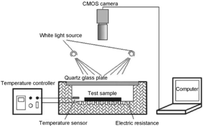
Fig. 5는 제시 된 비접촉식 열팽창계수 측정법 시스템 의 모식도이다. 소형 가열로를 만들고 가열 stage 위에 폴 리머 필름 시편을 올려둔다. 가열로의 윗부분은 유리창 을 내어 이미지를 찍을 수 있도록 하였고, 대게 수~수십 cm 거리에 Complementary Metal-Oxide Semiconductor (CMOS) 또는 Charge-Coupled Device (CCD) 카메라를 셋 팅한다.
Fig. 2. Screen printed pressure sensors on flexible PI films.19)
Fig. 3. Electroplating and soldering of the metal pattern onto a porous PDMS surface.20)
Fig. 4. Schematic figure of reference square subset of reference image and target (or deformed) subset of the deformed image.21)
열변형을 측정하기 위해서는 Fig. 6과 같이 명암대비가 뚜렷한 스페클 패턴을 만들어줘야 한다. 가장 간단하고 효율적인 방법으로써 그림과 같이 흑 또는 백의 스프레 이를 적당히 분사하여 패턴을 형성한다. CMOS 카메라 를 이용하여 가열 전 시편의 사진을 기준 이미지로 설정 하고, 가열함에 따라 온도 별로 사진을 찍어서 열팽창량 변화 추이를 확인 할 수 있다.
Fig. 7는 고온에서 열팽창한 시편의 DIC 해석 이미지이 다. x, y 변형량 필드, 총 변형량 벡터 필드 등을 다양하 게 얻을 수 있으며, 측정 화면 내 전면 해석이 가능한 이 미지 측정법의 장점이 잘 드러난다. 위의 해석에서 영역 내 열변형률 결과값을 평균 내어 열팽창계수를 얻을 수 있다. 가열 시 열변형에 의해 측정 화면 내에서 시편이 강 체 회전을 할 수 밖에 없으므로 이를 보정 해줘야 한다.
이 방법으로 PI/SiO2 복합체 필름,21) PES, PEN 필름,22) PP, PVC 필름23)등의 다양한 폴리머 필름에 대한 열팽창 계수 측정 연구가 수행되었다. 기존의 TMA 등의 방법에 서 특히 오차가 컸던 10 ppm/K 이하 범위의 열팽창계수 를 정밀하게 측정하는 실험적, 광학적 방법도 제안되었
다.24,25) Diaz 등은 변형 해석을 위한 스페클 패턴 형성 방
법으로써 조영 증강(Contrast enhanced) 법을 사용하였 다.26) Bright field (BF), phase contrast (PC), polarized light (PL)의 현미경 모드를 이용하여 폴리머 필름의 자체적 미 시구조로 패턴을 만드는 방식을 차용했다. 이를 통해 스 프레이 용매와 화학적 반응을 할 수 있는 민감한 재료에 대한 실험도 가능해졌으며, 스프레이 코팅에 의해 열변 형 자체가 구속 되는 매우 얇은 폴리머 필름도 스프레이 코팅 등 외부적 구속에 대한 우려 없이 측정이 가능해졌다.
2.2. 탄성중합체의 열팽창계수 측정
탄성중합체(elastomer)의 종류인 실리콘 고무(PDMS, Ecoflex)등은 스트레쳐블 전자 기판의 대표적 기판이자 유연소자의 기계적 보호에 사용되며, 무른 접착제, 탄성 실링재 등의 넓은 적용 범위를 갖는다. 특히 이들의 열팽 창계수는 폴리머 중에서도 매우 큰데, 강성이 매우 낮아 기존의 접촉식 열팽창계수 측정은 정확도가 현저히 떨어 진다. 즉, 기존 TMA 시스템에서 시편과 그 팽창량을 측 정하기 위해 필요한 다양한 그립, 프로브들이 닿는 점에 서 국부적 변형이 심하게 발생하기 때문이다. 이에 Lee Fig. 5. Schematic drawing of the experimental set-up.21)
Fig. 6. Surface speckle image of a film specimen, the area inside the yellow rectangle is calculation area.21)
Fig. 7. Thermal deformation fields of pure copper specimen after eliminating rigid body rotation: (a) u displacement field, (b) v displacement field and (c) Displacement vector field.21)
Fig. 8. A schematic of the experimental setup (side view).27)
에서는 시편을 수직으로 세워서 잡는 방식을 채택했다.
측정 효율성을 위해 Fig. 9과 같이 시편의 표점 쌍을 설 정하여 실시간(1 Hz) 변형량을 측정하였으며, 3D DIC 시 스템의 넓은 측정 부피를 활용하여 폭 8 mm 크기의 시 편 5개를 동시 측정하였다. 비접촉식 광학측정에서 얻을 수 있는 또 하나의 큰 장점을 구현하였다. Fig. 9(b)는 다 섯 개의 표준 시료에 대한 열팽창 변형률 측정 결과이다.
18 µm 두께의 얇은 알루미늄박부터 3.4 ppm/oC의 낮은 CTE을 갖는 실리콘 웨이퍼까지 다양한 적용성과 정밀도 가 확인되었다.
연성재료로 PDMS, Ecoflex 0010, 0030, 0050의 총 네 가 지 silicone rubber가 시험되었다. 그립 부에서의 국부 변 형도 최소화하기 위해, Fig. 10과 같이 시편과 유리 플랫 폼 사이의 반 데르 발스 힘으로 시편을 부착하였다. 이로
써 시편의 아랫쪽 절반인 5 mm 길이는 어떤 구속도 받 지 않게 된다. 또한 8개의 시편을 동시에 측정하는 고능 률성이 강조되었고, 사진과 같이 시편의 크기와 DIC의 측정 부피 조절에 따라 고능률성을 훨씬 향상 할 수 있음 을 예상 할 수 있다.
Fig. 11은 네 종의 실리콘 고무의 열팽창량 측정 결과 이다. 제품 가용 온도 범위인 200oC를 고려하여 상온에
Fig. 9. (a) Reference images were obtained from the left CCD image sensor for the five specimens: Si wafer, Cu foil, Al foil, SUS 630, and SUS 301. A pair of measuring points were selected on each sample via pattern recognition. (b) The thermal strain-temperature graphs obtained from the simultaneous CTE measurements in the temperature range of 40~180oC27) (Reprinted from Ref. [27]).
speckle pattern. Specimens are freely suspended being attached to a slide glass covering half of its length:
Sylgard PDMS, Ecoflex 00-10, Ecoflex 00-30, and Ecoflex 00-50. (b) Side view schematic of the custom fixture where the elastomer samples are attached27) (Reprinted from Ref. [27]).
Fig. 11. (a) The thermal strain-temperature graph obtained from simultaneous CTE measurements of the four silicone elastomers: Sylgard PDMS, Ecoflex 00-10, Ecoflex 00- 30, and Ecoflex 00-50. (b) The calculated CTE values of each silicone elastomer.27)
서 180oC까지 측정하였고, 구간 내 모두 선형의 열팽창 을 보였다. Fig. 11(b)의 좁은 에러 바에서 알 수 있듯이 최소 3개 이상의 반복시험에서 매우 일관된 CTE 값을 얻 었고, 이는 기존 TMA 방법의 측정값 산포를 혁신적으로 줄인 결과이다. PDMS인 Sylgard 184의 경우 mixing ratio 5:1에서 50:1까지 탄성 계수가 100배 이상 차이 나는 넓 은 범위에서의 CTE 값 정밀 측정값을 보고 했으며, 보고 된 바 없던 Ecoflex의 CTE 값도 처음 보고하였다.
3. 초박형 폴리머 필름의 인장 물성 측정 박형의 폴리머 필름은 패키징 친환경 배리어에서부터 세퍼레이터의 필터, 솔라셀의 파워 제너레이터까지 다양 한 분야에서 사용된다.28-30)폴리머의 두께가 얇아짐에 따 라 여러 분야에서 적용이 가능하지만 두께에 따른 물성 변화의 정확한 이해 없이는 사용이 제한된다. 앞서 설명 하였듯 폴리머 무른 특성으로 인해 기존의 인장 장비로 원하는 인장 응력을 가하기가 힘들다. 지그의 그립의 힘 이 약하면 시편은 슬립이 일어나게 되고 힘이 강하면 폴 리머가 그립 부분에서 응력을 많이 받아 찢어지게 된다.
이에 폴리머의 인장 물성을 옳게 측정할 수 있는 기술이 요구되었다.
Fig. 12는 초박형 필름의 인장 시험(UFT-Ultrathin Film Tensile)의 모식도이다. 필름이 얇아질수록 강성이 감소하 여 프리스탠딩 상태를 유지하기가 힘들다. 이를 해결하 기 위해, 초박형 필름을 물 위에 띄우고 클램프를 이용하 여 필름을 당기게 하였다. 당겨지는 힘은 오른쪽에 위치 한 외팔보의 변형을 광학 레이저로 측정하여 계산한다.
탄성 계수 측정뿐만 아니라 인장 파단 응력도 측정이 가
능하며 측정 결과는 Fig. 13에 나타내었다.
외팔보에 걸리는 힘을 측정하기 위해 사용된 레이저의 분해능은 10 μm이며 리니어 액추에이터의 분해능은 48 nm이다. 필름을 측정 가능한 상태로 셋업하기 위해서 물 이 사용되었고 물의 표면 장력을 이용하여 필름이 가라 앉지 않고 평평한 상태를 유지하게 된다. 필름을 당기기 위한 그립은 기존의 인장 실험 장비와는 다르게 긴 막대 모양을 이용하였다. 왼쪽의 클램프는 수조와 연결되어 리 니어 엑츄에이터가 움직이는 것과 동일하게 움직이고 외 팔보에 달린 그립은 필름이 당겨지는 것을 측정하는 역 할을 한다. 필름과 그립의 표면은 충분한 접합력을 만들 기 위해 polystyrene (PS) 코팅을 하였다.
물 위에 있는 필름이 표면장력으로 인한 물성 측정에
Fig. 12. A schematic of UFT for ultrathin films. The capable testing film thickness hF is comparable to the bulk polymer chain end to end distance Ree.31)
Fig. 13. (a) Schematic of surface tension acting on the thin film (b) Comparison between elastic energy and surface energy as a function of strain.31)
Fig. 14. Six polystyrene (PS) films of varying thicknesses stretch- ing until break, each yields a stress-strain response.31)
영향을 주는지를 정량적으로 분석하기 위해 Fig. 13과 같 이 분석을 하였다. 필름에 작용하는 표면장력으로 인한 에너지와 탄성 변형으로 인한 에너지의 비교를 통하여 두 께가 얇아질수록 표면장력의 영향이 적어지는 것을 확인 할 수 있다.
초박형 필름의 인장 실험을 통해 측정된 나노 사이즈 polystyrene (PS)을 두께 별로 측정한 데이터를 Fig. 14를 통해서 확인 할 수 있다. 15 nm부터 160 nm 두께를 바꾸 어가며 파단이 일어날 때까지 인장하였다. 측정된 인장
물성은 두께가 얇아질수록 낮아지는 것으로 관찰 되었다.
이처럼 소재가 박형이 되면서 물성이 달라지게 되므로 유 연 소자를 만들 때에 고려를 해주어야 한다. 따라서 이를 측정할 수 있는 기술은 매우 중요하다.
박판 폴리머는 유연한 특성으로 인해 태양 전지에도 유 망한 소재로 각광받고 있다.12,13)유기 고분자 태양전지 (Polymer Solar Cells)는 실리콘 기반의 태양전지에 비해 경제적인 이점을 가지고 있다. 또한 가공이 손쉬워 roll- to-roll printing, ink-jet printing, spin-coating 등의 용액 공 정을 기반으로 하여 대면적 소자 제작이 용이하다는 장 점을 통해 대용량의 상업적 생산이 필수적으로 요구되는 태양전지분야에서 지속적으로 주목 받고 있다.32-34) 고분 자-고분자 유기태양전지(All-polymer solar cell)는 폴리머 -도너와 폴리머-어셉터로 이루진 태양전지로서 높은 안 정성을 가지며 화학적, 전기적 특성을 조절할 수 있다는 장점을 가지고 있다.35,36) 하지만 기계적 신뢰성이 바탕이 되지 않는다면 태양전지로서의 역할을 다 할 수 없기 때 문에 기계적 물성측정이 중요하다. Fig. 15는 도너와 어 셉터가 되는 폴리머 소재의 기계적 특성을 측정한 데이 터를 나타낸 것이다. 탄성 계수와 파괴인성의 값은 필름 을 물 위에 띄워 측정한 것이다. Pseudo free-standing tensile test라고 불리는 물성 측정 방법은 필름을 물 위에 띄우고 시편을 직접 DIC 장비를 이용하여 시편이 인장되 는 정도를 추적하여 인장 물성을 측정하는 방법이다.37) 초박형 금속 필름에서부터 폴리머까지 여러가지 필름의 물성 측정이 가능하다.
Fig. 16은 Pseudo free-standing tensile test를 설명한 그림 이다. 3축으로 움직임이 가능한 load cell이 물 위에 있는 필름을 당기고 필름에 있는 파티클 패턴을 추적하는 DIC 장비를 이용해 변형률을 측정한다. 그립과 필름은 반 데 Fig. 15. Tensile test of electron donor polymer and electron
acceptor polymer. (a) Strain-stress curves and (b) Tough- ness of PBDTTTPD:PCBM and PBDTTTPD:P (NDI2HD- T) blend films. (The inset in a shows photographs of the BHJ blend film floating on water. The specimens were gripped by the PDMS-coated Al grips and the films were prepared under the optimized device condition). (c) Optical microscopy images of PBDTTTPD:PCBM (1:0.5 w/w) and PBDTTTPD:P(NDI2HD-T) (1.3:1 w/w) blend films when the films were under different strains.30)
Fig. 16. (a) The tensile testing system consists of a load cell, a linear stage and a DIC camera on an anti-vibration table.
(b) The ultra-thin Au film afloat on the water surface (c) The ultra-thin Au film specimen is strongly gripped by van der Waals adhesion between the PDMS coating on the grips and the specimen surface. (d) Tensile test is performed by linear stage (e) Drag force measurement has been made by attaching only one side of the specimen to the load cell connected to the linear stage.37)
르 발스 힘에 의해서 붙게 된다. 시편이 물 받는 물의 저 항과 전단응력에 비해 반 데르 발스 힘이 커 미끄러짐 없 이 인장이 가능하다.
4. 유연 FR4 기판의 굽힘 탄성계수 측정 단일 소재로서 쓰이는 폴리머 외에에도 복합재료 폴리 머 역시 유연 소자에 널리 쓰이고 있다. FR4 기판은 glass fiber reinforced polymer (GFRP)로서 유리 섬유와 에폭시 레진으로 이루어져 있다. 가볍고 강한 특징을 지니며 공 정시 열, 습기기 등으로부터 전기적 부품들을 보호하는 역할도 하고 있다. 기존의 인쇄 회로 기반(Printed Circuit Board, PCB)에서 널리 쓰이고 있으며 업계의 트렌드에 따라 기판의 두께는 100 µm 수준으로 얇아졌다.38)또한 여러 종류의 FR4기판이 개발됨에 따라 응용분야는 더욱 더 넓어지게 되었다.39,40) Fig. 17은 FR4 기판의 응용분야 를 나타낸 것이다. 투명한 GFRP기판은 유연 디스플레이, 유연 태양전지와 같은 응용분야의 문을 열고 있다.
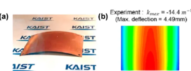
하지만 기판의 두께가 얇아짐에 따라 기판의 유연성 은 커졌지만 강성이 줄어들었기 때문에 Fig. 18 처럼 기 판의 워피지 문제가 생기게 된다.41,42) 기판의 워피지는 공정 과정에서 혹은 공정 후에 생기는데 레이어간의 열 팽창계수의 차이 혹은 도금 등에서 기인한 잔류응력에 의해 발생한다.41) 따라서 워피지를 정량적으로 분석하기
위해서는 재료의 기계적 물성을 정확하게 측정할 필요 가 있다.
FR4 시편의 구조는 Fig. 19에 나타나 있다. 유리 섬유 가 동일한 패턴으로 직교해있고 얇은 에폭시 레진이 그 것을 감싸며 표면을 형성하고 있다. 이 복합체 기판은 전 기적, 열적으로 절연체와 단열재의 역할을 하며 현재 PCB 양산 시스템에서 구리 기판이 양쪽에 합판되어 있는 copper clad laminate (CCL) 형태로 사용 되고 있다.
재료의 탄성 계수를 측정하는 여러 측정 방법 중 대표 적으로 인장 시험과 굽힘 시험이 있다. 보통의 재료에 대 해 두 시험법으로 구한 탄성 계수가 값이 같지만, 단일 유 리섬유 층을 갖는 FR4 기판처럼 두께 방향의 재료 불균 질성이 큰 경우 그 값이 큰 차이를 보일 것이다. 하지만 이 유연 FR4 기판이 실제 산업에서 양산 되고 다양한 적 용 분야를 갖게 된 것은 최근의 일이기 때문에 이 인장, 굽힘 탄성 계수의 차이에 대한 논의가 부족했다. 특히 유
Fig. 17. (a) A photograph of the 350-GFRHybrimer film.40) (b) Image of a flexible a-Si based solar cell fabricated on the GFRHybrimer substrate. The solar cell was fabricated at 250oC using a photo-CVD and a RF-PECVD system39) (Reprinted from Ref. [40, 39]).
Fig. 18. Type A FRP specimen with 17 µm Cu film at 180 °C:
(a) Specimen in the heating chamber; (b) Z-deflection contour measured by 3D scanner (top view).41)
Fig. 19. (a) Top view of FR4 substrate (b) Cross-sectional SEM image of the flexible substrate.38) (Reprinted from Ref.
[38]).
Fig. 20. Dominant deformation of a specimen under three-point bending configuration at a short span: (a) Shear deflection for a thin FR4 substrate and (b) Pure bending for a homogeneous solid material.38)
력에 대해 더 취약하여, 면내 인장압축 병형이 아닌 면외 전단 변형이 두드러지게 나타난다. 반면에 단일 재료의 경우에는 모든 방향에 대한 물성이 같아 FR4 시편에 비 해 지지점 위치에 덜 민감하게 된다. 따라서 시편 두께에 대해 약 60배 이상의 지지점 간격에서 굽힘 시험을 할 것 이 권고 되고 있다.
Fig. 21은 FR4의 시편의 인장 시험으로 측정한 인장 탄 성 계수와 3점 굽힘 시험으로 측정한 굽힘 탄성 계수를 비교한 그림이다. 인장 탄성 계수는 굽힘 탄성 계수에 비 해 전체적으로 높게 측정이 되었고 시편의 방향 별로 물 성차이를 보인다. 방향 별 물성 차이는 인장 탄성 계수가 굽힘 탄성 계수에 비해 크게 나타나는데, 이는 인장 시험
성 계수가 변하는 경향이 굽힘 시험과 인장 시험과 다른 점이 주목 할 만하다. 인장 탄성 계수는 온도가 증가할 때 모든 구간에서 선형적으로 감소를 하고 있지만 굽힘 탄 성 계수의 경우는 유리 전이 온도 전까지 감소하는 폭이 인장 탄성 계수에 비해 적다가 유리 전이 온도 후에 그 기울기가 증가한다. 앞서 설명했듯이 FR4 기판의 인장 탄성 계수는 많은 부분이 유리 섬유에 의해서 결정이 된 다. 따라서 인장 탄성 계수의 감소는 에폭시의 유리 전이 온도에 관계없이 일정하게 되고 굽힘 탄성 계수는 유리 전이 온도에 영향을 받게 된다.
5. 결 론
본 논문에서는 유연/신축성을 지니는 전자 패키징 용 폴리머 재료의 물성 측정 방법을 소개하였다. 기존의 상 용화된 제품이 소형화, 박형화, 경량화 되면서 제품에 사 용되는 폴리머 역시 제품의 사양을 만족하도록 요구되고 있다. 이에 따라 완성도가 높은 제품을 설계하기 위해서 는 폴리머 재료의 정확한 물성 측정 및 반영이 매우 중요 하게 되었다. 유연/신축성 폴리머의 열팽창계수는 패키징 에 사용되는 다른 재료들에 비해 크기 때문에 정확한 값 이 제품 설계에 반영되지 못하면 제작 공정 및 사용 중에 예측하지 못한 변형과 관련된 문제가 발생할 수 있다. 이 에 유연 기판에 쓰이는 얇은 폴리머 재료의 열팽창 계수 를 DIC 시스템을 이용하여 비접촉식으로 측정한 방법을 소개하였다. 여러 개의 시편을 동시에 넓은 측정 범위로 처리할 수 있어서 다양한 재료에 적용이 가능하다. 또한 초박형 폴리머 필름의 인장 물성을 측정하기 위해 물을 이용하여 필름을 pseudo free standing 상태로 만들어 인 장 시험하는 방법을 소개하였다. 나노미터 두께의 폴리 머 박막의 측정이 가능하며 두께변화에 따른 물성의 변 화가 있는 것을 확인함으로 제품 설계에 반영할 수 있도 록 하였다. 마지막으로 FR4 기판의 얇아진 두께로 생기 는 휨 문제 분석에 필요한 굽힘 물성 측정 방법을 알아보 았다. 폴리머의 무른 특성으로 인해 측정 방법에 어려움 이 있고 고려해야하는 점이 많지만 IT 업계의 트렌드에 맞추어 유연/신축성을 가지는 전자 패키징을 완성하기 위 해서는 패키징에 들어가는 재료의 정확한 물성 측정을 통 해 기계적 신뢰성을 높이는 연구가 필수적이다.
Fig. 21. (a) Flexural and tensile moduli for the specimen cut in four different directions with respect to the warp direction (0°) (b) Comparison of flexural and tensile moduli at different temperatures from 30 to 300°C.38)
감사의 글
This work was supported by Basic Science Research Program of the National Research Foundation under the Ministry of Science (2015R1A1A1A05001115), the Global Frontier R&D Program on Center for Multiscale Energy System (2011-0031569), and the Graphene Materials and Components Development Program of MOTIE/KEIT (10044412, Development of basic and applied technologies for OLEDs with graphene).
References
1. S. H. Chae, W. J. Yu, J. J. Bae, D. L. Duong, D. Perello, H.
Y. Jeong, Q. H. Ta, T. H. Ly, Q. A. Vu and M. Yun, “Trans- ferred wrinkled Al2O3 for highly stretchable and transparent graphene-carbon nanotube transistors”, Nat. Mater., 12, 403 (2013).
2. M. Kaltenbrunner, T. Sekitani, J. Reeder, T. Yokota, K. Kurib- ara, T. Tokuhara, M. Drack, R. Schwödiauer, I. Graz and S.
Bauer-Gogonea, “An ultra-lightweight design for impercepti- ble plastic electronics”, Nature, 499, 458 (2013).
3. Y. Chen, J. Au, P. Kazlas, A. Ritenour, H. Gates and M.
McCreary, “Electronic paper: Flexible active-matrix elec- tronic ink display”, Nature, 423, 136 (2003).
4. B. Lahey, A. Girouard, W. Burleson and R. Vertegaal, “Paper- Phone: understanding the use of bend gestures in mobile devices with flexible electronic paper displays”, Proc the SIG- CHI Conference on Human Factors in Computing Systems. Vancouver, 1303 (ACM) (2011).
5. H. J. Yen, C. J. Chen and G. S. Liou, “Flexible Multi-Colored Electrochromic and Volatile Polymer Memory Devices Derived from Starburst Triarylamine-Based Electroactive Polyimide”, Adv. Funct. Mater., 23, 5307 (2013).
6. Y.-C. Lai, Y.-C. Huang, T.-Y. Lin, Y.-X. Wang, C.-Y. Chang, Y. Li, T.-Y. Lin, B.-W. Ye, Y.-P. Hsieh and W.-F. Su, “Stretch- able organic memory: toward learnable and digitized stretch- able electronic applications”, NPG Asia Materials, 6, e87 (2014).
7. M. S. White, M. Kaltenbrunner, E. D. Głowacki, K. Gut- nichenko, G. Kettlgruber, I. Graz, S. Aazou, C. Ulbricht, D.
A. Egbe and M. C. Miron, “Ultrathin, highly flexible and stretchable PLEDs”, Nat. Photonics, 7, 811 (2013).
8. J. Liang, L. Li, X. Niu, Z. Yu and Q. Pei, “Elastomeric poly- mer light-emitting devices and displays”, Nat. Photonics, 7, 817 (2013).
9. C.-L. C. Chien, Y.-C. Huang, S.-F. Hu, C.-M. Chang, M.-C.
Yip and W. Fang, “Polymer dispensing and embossing tech- nology for the lens type LED packaging”, J. Micromech.
Microeng., 23, 065019 (2013).
10. S. Khan, L. Lorenzelli and R. S. Dahiya, “Technologies for printing sensors and electronics over large flexible substrates:
a review”, IEEE Sens. J, 15, 3164 (2015).
11. T. Yamada, Y. Hayamizu, Y. Yamamoto, Y. Yomogida, A.
Izadi-Najafabadi, D. N. Futaba and K. Hata, “A stretchable carbon nanotube strain sensor for human-motion detection”, Nat. Nanotechnol., 6, 296 (2011).
12. J. E. Carlé, M. Helgesen, M. V. Madsen, E. Bundgaard and F. C. Krebs, “Upscaling from single cells to modules-fabri- cation of vacuum-and ITO-free polymer solar cells on flexible substrates with long lifetime”, J Mater. Chem. C Mater. Opt.
Electron Devices,, 2, 1290 (2014).
13. M. Kaltenbrunner, M. S. White, E. D. Głowacki, T. Sekitani, T. Someya, N. S. Sariciftci and S. Bauer, “Ultrathin and light- weight organic solar cells with high flexibility”, Nat. Com- mun, 3, 770 (2012).
14. A. Gaikwad, A. Zamarayeva, J. Rousseau, H. Chu, I. Derin and D. Steingart, “Highly stretchable alkaline batteries based on an embedded conductive fabric”, Adv. Mater., 24, 5071 (2012).
15. G. Zhou, F. Li and H.-M. Cheng, “Progress in flexible lithium batteries and future prospects”, Energy. Environ. Sci., 7, 1307 (2014).
16. NSC, National Standard Coordinator. from http://www.kscodi.or.kr /?mid=year_2014_sub03_01.
17. D.-H. Kim, N. Lu, R. Ma, Y.-S. Kim, R.-H. Kim, S. Wang, J. Wu, S. M. Won, H. Tao and A. Islam, “Epidermal elec- tronics”, Science, 333, 838 (2011).
18. D. J. Lipomi, M. Vosgueritchian, B. C. Tee, S. L. Hellstrom, J. A. Lee, C. H. Fox and Z. Bao, “Skin-like pressure and strain sensors based on transparent elastic films of carbon nanotubes”, Nat. Nanotechnol., 6, 788 (2011).
19. W.-Y. Chang, T.-H. Fang, H.-J. Lin, Y.-T. Shen and Y.-C. Lin,
“A large area flexible array sensors using screen printing tech- nology”, J. Display Technol., 5, 178 (2009).
20. G. S. Jeong, D.-H. Baek, H. C. Jung, J. H. Song, J. H. Moon, S. W. Hong, I. Y. Kim and S.-H. Lee, “Solderable and elec- troplatable flexible electronic circuit on a porous stretchable elastomer”, Nat. Commun, 3, 977 (2012).
21. P. Bing, X. Hui-min, H. Tao and A. Asundi, “Measurement of coefficient of thermal expansion of films using digital image correlation method”, Polym. Test., 28, 75 (2009).
22. D. Van den Berg, M. Barink, P. Giesen, E. Meinders and I.
Yakimets, “Hygroscopic and thermal micro deformations of plastic substrates for flexible electronics using digital image correlation”, Polym. Test., 30, 188 (2011).
23. C. Dudescu, A. Botean and M. Hardau, “Thermal expansion coefficient determination of polymeric materials using digital image correlation”, Mater Plast, 50, 55 (2013).
24. Y. Wang and W. Tong, “A high resolution DIC technique for measuring small thermal expansion of film specimens”, Opt.
Lasers. Eng., 51, 30 (2013).
25. M. De Strycker, L. Schueremans, W. Van Paepegem and D.
Debruyne, “Measuring the thermal expansion coefficient of tubular steel specimens with digital image correlation tech- niques”, Opt. Lasers. Eng., 48, 978 (2010).
26. J. A. Diaz, R. J. Moon and J. P. Youngblood, “Contrast enhanced microscopy digital image correlation: a general method to contact-free coefficient of thermal expansion measurement of polymer films”, ACS Appl. Mater. Interfaces, 6, 4856 (2014).
27. T.-I. Lee, M. S. Kim and T.-S. Kim, “Contact-free thermal expansion measurement of very soft elastomers using digital image correlation”, Polym. Test., 51, 181 (2016).
28. H. Wang, J. K. Keum, A. Hiltner, E. Baer, B. Freeman, A.
Rozanski and A. Galeski, “Confined crystallization of poly- ethylene oxide in nanolayer assemblies”, Science, 323, 757 (2009).
Mater. today, 15, 36 (2012).
33. D. Angmo, T. T. Larsen-Olsen, M. Jørgensen, R. R. Sønder- gaard and F. C. Krebs, “Roll-to-Roll Inkjet Printing and Pho- tonic Sintering of Electrodes for ITO Free Polymer Solar Cell Modules and Facile Product Integration”, Adv. Energy Mater., 3, 172 (2013).
34. D. Angmo, S. A. Gevorgyan, T. T. Larsen-Olsen, R. R. Søn- dergaard, M. Hösel, M. Jørgensen, R. Gupta, G. U. Kulkarni and F. C. Krebs, “Scalability and stability of very thin, roll- to-roll processed, large area, indium-tin-oxide free polymer solar cell modules”, Org. Electron., 14, 984 (2013).
35. Y.-J. Hwang, G. Ren, N. M. Murari and S. A. Jenekhe, “n- type naphthalene diimide-biselenophene copolymer for all- polymer bulk heterojunction solar cells”, Macromolecules, 45, 9056 (2012).
36. A. Facchetti, “Polymer donor-polymer acceptor (all-polymer) solar cells”, Mater. Today, 16, 123 (2013).
37. J.-H. Kim, A. Nizami, Y. Hwangbo, B. Jang, H.-J. Lee, C.- S. Woo, S. Hyun and T.-S. Kim, “Tensile testing of ultra-thin films on water surface”, Nat. Commun, 4 (2013).
38. T.-I. Lee, C. Kim, M. S. Kim and T.-S. Kim, “Flexural and tensile moduli of flexible FR4 substrates”, Polym. Test.
(2016).
39. J. Jin, J. H. Ko, S. Yang and B. S. Bae, “Rollable Transparent Glass-Fabric Reinforced Composite Substrate for Flexible Devices”, Adv. Mater., 22, 4510 (2010).
40. H. Y. Kim, J. Jin, S.-H. Ko Park, I.-Y. Eom and B.-S. Bae,
• 김철규(金澈圭)
• 한국과학기술원 기계공학과
• 구조해석 시뮬레이션, 기판 휨 분석
• 이태익 (李太翼)
• 한국과학기술원 기계공학과
• 전자패키지 신뢰성, 폴리머 기계적 물성
• 김택수 (金澤樹)
• 한국과학기술원 기계공학과
• 박막의 기계적 특성 및 신뢰성