N
UMERICALA
NALYSIS OFW
AVEC
HARACTERISTICSA
ROUNDP
ERMEABLES
UBMERGEDB
REAKWATER ON THEP
OROUSS
EABEDN.H. Kim* and S.M. Woo
Department of Civil Engineering, Jeju National Univ.
침투 해저면 위의 투과잠제주변 파랑특성의 수치해석
김 남 형,* 우 수 민
제주대학교 토목공학과
In this study, wave characteristics coming with oblique incident angle to permeable trapezoidal submerged breakwater on the porous seabed are calculated by using boundary element method. This numerical analysis, based on the wave pressure function, is analyzing the continuity in the analytical region including fluid and structure.
From the comparison of the reflection coefficients and damping coefficient, the results of this study are in good agreement with the existing results. The peak values of reflection coefficient obtained by permeable trapezoidal submerged breakwater on the porous seabed are smaller than those of permeable trapezoidal submerged breakwater on the non-porous seabed. The velocity vector in front of permeable trapezoidal submerged breakwater on the porous seabed is smaller than that in front of permeable trapezoidal submerged breakwater on the non-porous seabed with out the energy loss.
Key Words : Wave Pressure Function, Permeable Submerged Breakwater, Wave Velocity, Reflection Coefficients
Received: May 7, 2014, Revised: August 21, 2014, Accepted: August 21, 2014.
* Corresponding author, E-mail: [email protected] DOI http://dx.doi.org/10.6112/kscfe.2014.19.3.008
Ⓒ KSCFE 2014
1. Introduction
The development and utilization of ocean have been increasing as the economic and living standard grows.
Also, before assessing the construction of structure in protecting a harbor and beach from ocean waves, the ability of an ocean engineer to predict wave profiles is an important role.
The crowns of dissipating structures such as the existing breakwater are over the surface of sea water. It is negative in terms of landscape and marine environment to block the flow of seawater. On the other hand, the submerged breakwater has advantages in terms of the quality of water and the scenic view. In addition, the effect in case of the submerged breakwater is better than
without the submerged breakwater in controlling the beach erosion. These submerged breakwaters have been constructed on the porous seabed in shallow water.
Many researches have been done about submerged breakwater. Dattatri et al.[1] performed a wide ranging laboratory study of submerged breakwater and found that the influential parameters concerning transmission coefficient are the relative crest width and the relative depth of submergence. Ijima & Sasaki[2] computed the effect of a submerged breakwater calculated using Domain Decompostion Method. Chen et al.[3] investigated a thin submerged breakwater. Their solution is based on the dual integral formulation for the Modified Helmholtz equation.
Takikawa & Kim[4], Kim[5] and Kim & Woo[6] analyzed the submerged breakwater in the case of non-porous seabed by the Wave Pressure Function. In addition, Liu &
Dalrymple[7] obtained the solution of laminar boundary layer on the porous seabed by replacing Darcy's law with the modified Dagan's porous flow model. More recently, Kim et al.[8] carried out the wave damping analysis in a porous seabed without oblique incident waves.
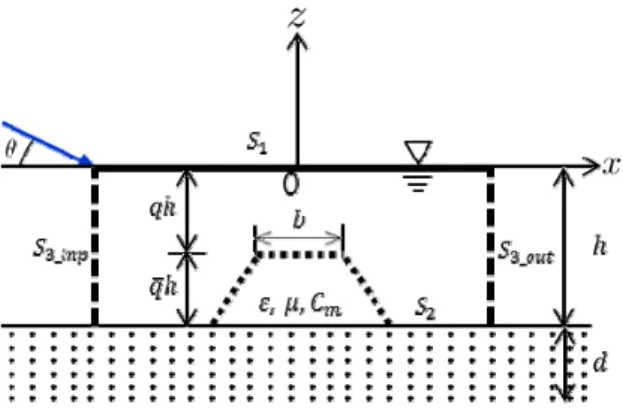
Fig. 1 Analytical Region and Coordinate
The objective of this study is to analyze interactions between the oblique incident wave and permeable submerged breakwater on the porous seabed.
2. Basic equation 2.1 Governing equation
The submerged breakwater is placed in the water of uniform depth as shown in Fig. 1, in which is the finite depth of the porous seabed. The fluid region is surrounded with free surface boundary , porous seabed boundary , and open boundaries
and
, respectively. It is assumed that the fluid is inviscid, and incompressible, its motion is irrotational. Therefore, the velocity potential can be defined as follows:
(1) where is the angular frequency. The velocity potential
satisfies the following Laplace equation.
(2)
The velocity potential can be written as following equation(3), which satisfies the small amplitude wave theory.
cos cos ·
cos·
·cosh sinh
(3)where and denote the velocity potential at the input and output position, respectively, is the wave amplitude, and are the unknown variables corresponding to the reflected and transmitted waves and
is the wave number. The unknown coefficients , and the dispersion relationship can be obtained by using the boundary conditions.
Since the variation of velocity potential to the axis is expressed as sin within the flow domain, an unknown function meaning the variation of potential is expressed as
in plane, so that the velocity potential on the fluid motion in the flow domains are given as follows[9]:
sin (4) Substituting Eq. (4) into Eq. (2), Helmholtz equation in terms of the unknown potential function is obtained as follows:
sin (5) When the movement of water particles accelerates, the energy dissipation term acts on the fluid resistance as an added mass force. In this study, the energy dissipation is modeled by introducing a linear dissipation coefficient and an added mass coefficient into the nonlinear energy dissipation terms. This is expressed as follows[4]:
·
‧
·
(6)where is Pressure, denotes the porosity.
2.2 Boundary conditions
The boundary conditions in the analytical domain can be written as follows:
Free surface boundary ;
(7)Porous seabed boundary with finite depth ;
at (8a)
at (8b) Open boundary ;
(9) where is the soil domain pressure, is the normal drawn outwardly on the boundaries, is the coefficient of permeability, and is the exterior velocity potential at the junction of analytical regions.
The continuity conditions such as mass-flux and energy-flux of fluid motion at each boundary must be satisfied as follows:
Mass-flux ;
(10) Energy-flux ;
≡ (11)where is the wave pressure component. As an analytical method, the problem for the unknown velocity potential applying Eq. (5) and Eq. (7)-(11) can be solved. However the analytical method for the unknown velocity potential must satisfy Eq. (10) and Eq. (11) at the junction of each domain because the velocity potential
is a discontinuous function.
In this study, the analysis using the wave pressure component as an unknown variable is carried out, in which the wave pressure component is continuos throughout the analytical region. Considering the periodical motion of the incident wave frequency , the wave pressure function is expressed by:
(12) From Eq. (10) and Eq. (11), the velocity potential is defined as follows:
·
· ·
·
(13)
where is . Using Eq. (13), each of the boundary
conditions can be rewritten as follows:
All domains ;
sin·
Free surface boundary ;
Porous seabed boundary with finite depth ;
Open boundary ;
(14)
The open boundary condition can be expressed as follows:
Input boundary ;
cos cos ·
cos cos cos · Output boundary
;
cos ·
cos· cos ·
(15)The dispersion relationship for the porous seabed boundary conditions is given as follows[10]:
tanh
tanh
tanh (16)where and is the kinematical viscosity. The dispersion relationship yields a complex valued , which may be written as The real component of represents the real wave number, which is related to the wave length.
2.3 Formulation by BEM
Let and be two points on the boundaries, and let be the distance between and as shown in Fig. 2; from Green’s second identity, because
Fig. 2 Definition of notation
the velocity potential is a harmonic function, the following equations are obtained as follows:
·
·
·
sin
(17)where ( ⋯) is the interior angle between two tangents at nodal point as shown in Fig. 2. is the fundamental solution, which satisfies the Helmholtz equation and is defined by the Modified Bessel functions of the second kind. When incident wave proceeds perpendicularly, is calculated as ln.
2.4 Formulation about domain
As shown in Fig. 2, analytical domain is divided with
elements and nodal points. The coordinates nodal point of each element is denoted by ( …), and the length of each element is
∆ ⋯. The uniform depth input and output boundary and are established at two wave length distance from the structure. The normal wave velocity and the integral direction are counterclockwise.
Combining Eq. (17) with Eq. (14), Eq. (15), and Eq. (16), the following equation is obtained as follows[8];
(18)
where
,
and
are the arbitrary point on the input and output open boundary, respectively.
Fig. 3 Dimensionless damping coefficient versus relative depth
Fig. 4 Comparison of squared transmission coefficients for shoal ( × )
3. Verifications and applications
The change of dimensionless damping coefficient is influenced in shallow water as shown Fig. 3. ∞ means infinite depth of the rigid porous seabed. circle symbol is the results obtained by Reid and Kajiura[10].
Also, The dimensionless damping coefficient is decreased with the decreasing relative depth.
Fig. 4 is the comparison of squared transmission coefficients. In Fig. 4 circle symbol is the results obtained by Do & Suh[11] and solid line is the results obtained in this study.
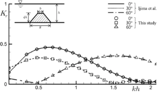
When an oblique incident wave with incident wave angle of , , is propagating over an impermeable trapezoidal submerged breakwater, variations
Fig. 5 Reflection coefficients for the change of angle ( )
of reflection coefficient versus the dimensionless wave length are indicated in Fig. 5. In Fig. 5 solid lines are the results obtained by Ijima et al.[9] using the Domain Decomposition Method, and circle, square, triangle symbol are the results obtained in this study. From the comparisons in Fig. 4 and Fig. 5, the numerical results obtained in this study show good agreement. It means that this analytical method is verified by validity and availability.
Fig. 6 shows the reflection coefficients of permeable submerged breakwater due to incident wave angle(
) on the non-porous seabed( ).
The reflection coefficients of permeable submerged breakwater on the porous seabed( × ) under the same conditions in Fig. 6 are shown in Fig. 7. Also, the tendency of reflection coefficients decreases as the incident wave angle increases.
From Fig. 8(a), the velocity vector and wave profiles over permeable trapezoidal submerged breakwater with different incident waves angle on the non-porous seabed is shown at . The velocity vector and wave profiles over permeable trapezoidal submerged breakwater on the porous seabed is shown under the same conditions in Fig. 8(a).
From Fig. 8, the values of the velocity vector and wave profiles passing over a permeable trapezoidal submerged breakwater on non-porous and porous seabed are decreased rapidly, respectively.
4. Conclusions
In this study based on the wave pressure function, wave characteristics are calculated for the effect of the permeable trapezoidal submerged breakwater on the porous seabed. The following conclusions by the numerical
Fig. 6 Comparison of reflection coefficients on the non-porous seabed
Fig. 7 Comparison of reflection coefficients on the porous seabed
×
analysis can be drawn :
(1) The peak values of reflection coefficient obtained by permeable trapezoidal submerged breakwater on the porous seabed with the finite depth are smaller than those of permeable trapezoidal submerged breakwater on the non-porous seabed regardless incident wave angle.
(2) As incident wave angle increases, the number of peak values of reflection coefficient on the non-porous seabed is increased as shown Fig. 6 whereas the peak values of reflection coefficient on the porous seabed show one value respectively as shown in Fig. 7.
(3) The velocity vector and wave profiles in front of permeable trapezoidal submerged breakwater on the porous seabed is smaller than that in front of
(a) Non-porous seabed ( ,
) (b) Porous seabed ( , × )
Fig. 8 Comparisons of velocity vector over permeable trapezoidal permeable submerged breakwater on the non-porous and porous seabed due to oblique incident waves at
permeable trapezoidal submerged breakwater on the non-porous seabed without the energy loss.
Acknowledgment
This research was supported by the 2014 scientific promotion program funded by Jeju National University.
References
[1] 1978, Dattatri, J., Raman, H. and Shankar, abd N.J.,
"Performance Characteristics of Submerged Breakwaters," Proceedings of the 16th Coastal Engineering Conference, ASCE, pp.2153-2171.
[2] 1971, Ijima, T. and Sasaki, T., "Theoretical Study on the Effect of a Submerged Breakwater," Proceedings 18th Japanese Conference on Coastal Engineering, JSCE, pp.141-147.
[3] 2002, Chen, K.H., Chen, J.T., Chou., C.R. and Yueh, C.Y., "Dual Boundary Element Analysis of Oblique Incident Wave passing a Thin Submerged Breakwater,"
Engineering Analysis with Boundary Elements, Vol.26, pp.917-928.
[4] 1992, Takikawa, K. and Kim, N.H., "An Analytical Technique for Permeable Breakwaters using Boundary Element Method," Engineering Analysis with Boundary Elements, Vol.10, No.4, pp.299-305.
[5] 1995, Kim, N.H., "Analysis of the Wave
Characteristics of Parallel Submerged Porous Breakwaters by Boundary Element Method," Journal of the Korean Society of Civil Engineers, KSCE, Vol.15, No.2, pp.425-431.
[6] 2012, Kim, N.H. and Woo, S.M., "The Boundary Element Analysis of Waves coming with Oblique Angle to a Submerged Breakwater," Journal of the Korean Society of Civil Engineers, KSCE, Vol.32, No.5B, pp.295-300.
[7] 1984, Liu, P.L.-F. and Darymple, R.A., "The Damping of Gravity Water-Waves due to Percolation," Costal Engineering, Vol.8, pp.33-49.
[8] 2006, Kim, N.H., Young, Y.L., Yang, S.B. and Park, K.I., "Wave Damping Analysis in a Porous Sea-bed,"
Journal of Civil Engineering, KSCE, Vol.10, No.5, pp.305-310.
[9] 1982, Ijima, T., Yoshida, A. and Kitayama, H.,
"Numerical Analysis on the Reflection Effect of Submerged Breakwater for Oblique Incident Wave,"
Proceedings 29th Japanese Conference on Coastal Engineering, JSCE, pp.418-422.
[10] 1957, Reid, R.O. and Kajiura, K., "On the Damping of Gravity Waves over a Permeable Sea Bed,"
Transactions - American Geophysical Union, Vol.38, No.5, pp.662-666.
[11] 2011, Do, K.D. and Suh, K.D., "Wave Damping over a Multilayered, Permeable Seabed," Journal of Coastal Research, Vol.27, No.6, pp.1183-1190.
![Fig. 4 is the comparison of squared transmission coefficients. In Fig. 4 circle symbol is the results obtained by Do & Suh[11] and solid line is the results obtained in this study.](https://thumb-ap.123doks.com/thumbv2/123dokinfo/5522053.460022/4.808.445.721.398.619/comparison-squared-transmission-coefficients-results-obtained-results-obtained.webp)