서론 I.
. 2035 ,
[1-3,8-10].
, ,
. , ,
,
.
, .
.
VTOL (Vrtical Take Off and
Landing) Hovering m
* (Corresponding Author)
: 2011. 1. 7., : 2011. 4. 6., : 2011. 6. 14.
, , , , , :
([email protected]/[email protected]/[email protected]/cjki [email protected]/[email protected]/[email protected])
(NRF) (2010-0006800)
(K20902001617) .
. (virtual instrumentation)
, ,
. Labview
GCS (Ground Control System) .
, GUI (Graphic
User Interface) ,
.
.
FCS (Flight Control System) National
Instrument sb-RIO .
sb-RIO LabVIEW
. FCS
,
.
Virtual Instrumentation
Development and Flight Test of Unmanned Autonomous Rotor Navigation System Based on Virtual Instrumentation Platform
*, , , , ,
(Byoungjin Lee1, Sangjun Park1, Seungjun Lee1, Changjoo Kim1, Young Jae Lee1, and Sangkyung Sung1)
1Konkuk University
Abstract: The objectives of this research are development of guidance, navigation and control system for RUAV on virtual instrumentation and real flight test. For this research, the system is divided to DAQ (data acquisition) section, actuator section and controller section. And the hardware and software on each sections are realized on LabVIEW base. Waypoint guidance and control of auto flight are realized using PID gain tuning and waypoint vector tracking guidance algorism. For safe flight test, auto/manual switching module isolated from FCS (Flight Control System) is developed. By using the switch module, swift mode change was achieved during emergency flight case. Consequently, a meter level error of flight performance is achieved.
Keywords: RUAV, virtual instrumentation platform, vector tracking guidance, LabVIEW, emergency, FCS
Copyright© ICROS 2011
의 기능 및 구성 II. Hardware
RC RC
PWM .
RC PWM FCS (Flight Control
System) PWM
.
, FCS AP
(Access Point) FCS GCS
. FCS
.
DAQ ,
.
.
1 [9].
1. Flight Control Computer (FCC) FCC
[4,10].
FCC NI (National Instrument)
sbRIO-9612 .
sbRIO-9612 267g
[5].
/
. 256MB
. 2M gate FPGA
Interrupt .
LabVIEW
. sbRIO .
sbRIO-9612 400MHz
2M gate FPGA .
FPGA RTOS
Interrupt . RS232
Packet FPGA , 1 Packet
1 Interrupt RTOS .
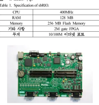
1. sbRIO .
Table 1. Specification of sbRIO.
CPU 400MHz
RAM 128 MB
Memory 256 MB Flash Memory
2M gate FPGA 10/100M
2. National Instrument sbRIO-9612.
Fig. 2. sbRIO-9612 manufactured by National Instrument.
3. RTOS FPGA .
Fig. 3. Functional separation between RTOS and FPGA.
Packet Byte 76byte Packet
100Hz GA3390H
data .
FPGA RTOS ,
. 2. Sensor
3 (inertial measurement unit)
MI-GA3390H .
GA3390H GPS/IMU 100Hz
. GPS
1. FCS .
Fig. 1. Overall configuration of FCS.
. ,
. GA3390H GPS
NovAtel OEMV-1G . OEMV-1G SBAS
m .
4. GA3390H.
Fig. 4. GA3390H from MicroInfinity.
5. NovAtel OEMV-1G.
Fig. 5. OEMV-1G from NovAtel.
6. Honeywell HPA200RTTA-AG.
Fig. 6. HPA200RTTA-AG from Honeywell.
7. Autonics BJN50-NDT.
Fig. 7. BJN50-NDT from Autonics.
GPS
m
.
Honeywell
HPA200RTTA-AG .
80cm . Rotor RPM
, ,
. RPM Autonics BJN50-NDT
. Pulse
. Rotor 1:1
1 1 .
30000RPM rotor .
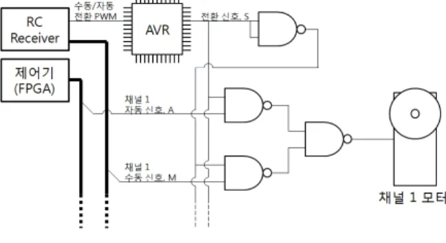
. 자동 수동 전환 모듈
3. /
.
.
8 . 74LS00 NAND
Gate
.
8 .
모터신호 ∙ ∙ ∙ ∙ (1)
S , A , M
. S 1
S 0 .
S A M
.
S FCS
ATmega128 . ATmega128
/ PWM S .
/
8. / .
Fig. 8. Switching module between Auto/Manual mode.
ATmega128 .
가상계측기반 알고리즘의 구성 III.
로직 1. Position Hold
.
.
.
2 RUAV
Logic . RUAV
, , /
. 0
.
, ,
.
. GA3390H
. PD
4
Butterworth Filter [6].
2 Roll, Pitch
I , P .
. ,
PI .
P , PI
. GPS
. IMU
.
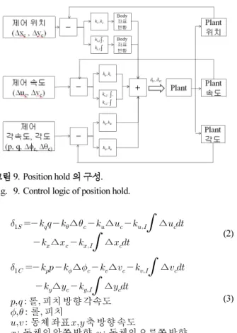
9 .
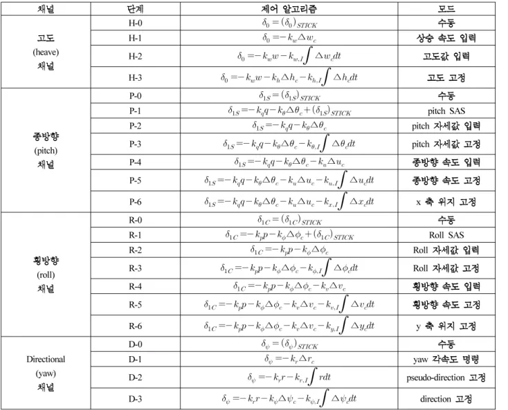
2. .
Table 2. Control Algorithm for each mode and channel.
(heave)
H-0
H-1 ∆
H-2
∆H-3 ∆
∆(pitch)
P-0
P-1 ∆ pitch SAS
P-2 ∆ pitch
P-3 ∆
∆ pitchP-4 ∆ ∆ P-5 ∆ ∆
∆P-6 ∆ ∆
∆ x(roll)
R-0
R-1 ∆ Roll SAS
R-2 ∆ Roll
R-3 ∆
∆ RollR-4 ∆ ∆
R-5 ∆ ∆
∆R-6 ∆ ∆
∆ yDirectional (yaw)
D-0
D-1 ∆ yaw
D-2
pseudo-directionD-3 ∆
∆ direction9. Position hold . Fig. 9. Control logic of position hold.
∆ ∆
∆ ∆
∆ (2) ∆ ∆
∆ ∆
∆ 롤 피치방향각속도
롤 피치
동체좌표축방향속도
동체의앞쪽방향 동체의오른쪽방향
(3)
(2), (3) 9
x y ,
.
FPGA
PWM .
로직 2. Yaw Control
Yaw
. Roll Pitch 5
Yaw
. Yaw
Damping .
PD Yaw
Yaw PID
. (4) Yaw .
∆
∆ 방향각속도 (4)
경로 유도 로직 3.
Yaw GA3390H d
. r
. r
.
(5)
: Yaw d:
Ψ
10. .
Fig. 10. Geometric representation of guidance control.
r d
.
. 기반 알고리즘 구현 4. LabVIEW
National
Instrument Labview
. LabVIEW C
. C
, /
LabVIEW
‘Block’
. Block
I/O FPGA,
Memory
. LabVIEW
‘data probe’ .
. ,
UDP/TCP Layer 5 protocol .
WiFi GCS
.
FCC RTOS FPFA ,
, , , PWM
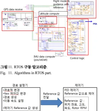
. 11, 13 LabVIEW
.
11 sbRIO-9612 RTOS FPGA
, LLH ENU
. RTOS
Reference
. 12
.
.
.
.
, , , Rotor RPM . RTOS
, ,
FPGA .
13 sbRIO-9612 FPGA
. FPGA FCS .
FPGA
FPGA
PWM . RTOS
FPGA PWM
.
FPGA Packet .
RTOS RS-232 Packet
Check Sum Packet .
Packet for Packet
. FPGA Packet
RTOS Interrupt Packet
. RTOS Check Sum
RTOS
. 14 FPGA
.
15 ‘Front Panel’
Gain
. Packet
LabVIEW PC sbRIO-9612
GPS data receive
altitude compute
IMU data compute (pos/vel/att)
Flight mode &
guidance with reference
Control logic
FPGA TX
RX
11. RTOS .
Fig. 11. Algorithms in RTOS part.
12. .
Fig. 12. Interaction between guidance and control part.
Pressure Data convert (link configure, bit compute)
GPS Check Sum
& Data acquire
IMU Check Sum &
Data acquire
Digital Data Processing (PWM receive/generate, RPM count)
13. FPGA .
Fig. 13. Algorithms in FPGA part.
14. FPGA Packet .
Fig. 14. Communication packet management via FPGA.
1
Simple GUI interaction for CMD/CON w/o packet configuration
Simple GUI interaction for CMD/CON w/o packet configuration
GCS for Navigation, Guidance &
command
GCS for display & mapping
15. GCS Front Panel .
Fig. 15. Capture from the developed GCS front panel.
.
비행 시험 IV.
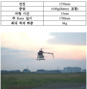
회전익 항공기 특징 및 제원 1.
. Plettenberg (HP370/40/A2)
3.5HP .
FCC .
. Kokam 5000mAh 6cell(22.2V)
2 .
15 .
모델링을 위한 실험 기동 2.
, ,
. .
50Hz
. 17
. lateral,
longitudunal, directional
. 3
3 PWM Pulsewidth( sec)μ
. .
PWM .
, PWM
. 18
( / ) PWM (
/ ) .
PWM
. 7 Hz
cutoff 4 .
경로점 비행 시험 결과 3.
trim -PWM
[11]
. PID
. ,
100m ( )
. (1)
3. .
Table 3. Physical specification of RUAV.
1550mm 4100g(Battery )
15min
Rotor 1700mm
6kg
16. .
Fig. 16. Rotary UAV in flight test.
17. Trim data.
Fig. 17. Trim flight test data.
1.65 1.7 1.75 1.8 1.85
x 105 -50
-40 -30 -20 -10 0 10 20 30
pitch rate vs. PWM
1.9 2 2.1 2.2 2.3 2.4 2.5 2.6 2.7
x 105 -200
-100 0 100 200
yaw rate vs. PWM
1.6 1.65 1.7 1.75 1.8 1.85
x 105 1200
1300 1400 1500 1600 1700
1.65 1.7 1.75 1.8 1.85
x 105 -50
-40 -30 -20 -10 0 10 20 30
pitch rate vs. PWM
1.9 2 2.1 2.2 2.3 2.4 2.5 2.6 2.7
x 105 -200
-100 0 100 200
yaw rate vs. PWM
1.6 1.65 1.7 1.75 1.8 1.85
x 105 1200
1300 1400 1500 1600 1700
1.9 2 2.1 2.2 2.3 2.4 2.5 2.6 2.7
x 105 1000
1200 1400 1600 1800
1.9 2 2.1 2.2 2.3 2.4 2.5 2.6 2.7
x 105 1000
1200 1400 1600 1800
18. , ( ) PWM (
).
Fig. 18. Pitch and yaw rate vs. PWM signal during manual flight.
.
15 Yaw ,
.
.
19 .
. m
5m 10 .
20
. 10m/s
Gain
.
Gain .
. 20 Yaw
. -90°, 180°, 90°, 0°, -90° Yaw Overshoot
.
-60 -50 -40 0 40 50 60
-110 -100 -90 -50 -10 0 10
x(m) y(m
)
1
2 3
4
21. .
Fig. 21. Flight trajectory of ribbon shape.
22. .
Fig. 22. Forward velocity and heading angle during ribbon flight.
(1)
(2), (3), (4)
. 21
. yawing
, PID 5m
.
. 22
.
.
,
. 22
Yaw . 180°, -45°, 45°, 180°
Yaw 3~4
Offset .
Offset
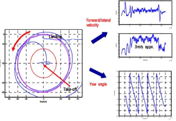
. 23
-60 -50 -40 0 40 50 60
-60 -50 -40 0 40 50 60
x(m ) y(m
)
start
2 1
3 4
19. .
Fig. 19. Flight trajectory of square shape.
20. .
Fig. 20. Forward velocity and heading angle during square flight.
, .
결론 V.
LabVIEW GPS
IMU FCS
. VTOL
m
, FCS
.
.
Labview ,
. , , GUI
,
FCS
.
.
PID
FCC .
.
.
. 참고문헌
[1] C.-H. Heo, M.-S. Roh, D.-W. Lee, and K.-R. Cho,
“Ground test of the flight control system using PC104,”
Journal of Korean Society for Aeronautical and Space Sciences, pp. 452-459, May 2007.
[2] S. Trimble, “US army predicts shift to nearly all unmanned aircraft by 2035,” Flight International, 2010.
[3] K. Alexis, “Coordination of helicopter UAVs for aerial forest-fire surveillance,” Applications of Intelligent Control to Engineering Systems, 2009.
[4] M.-H. Park, H. Ryu, l.-K. Ahn, and J.-E. Kim,
“Development of flight control computer in UAV,” Proc.
of KSAS Conference, pp. 289-292, Nov. 2000.
[5] National Instruments - Single-Board RIO OEM Devices, User Guide.
[6] J.-H. Lee, H. Ryu, J.-E. Kim, and E.-T. Kim,
“Development of automatic flight control system for unmanned aerial vehicle based on angular rate,”
Aerospace Engineering and Technology, vol. 4, no. 2.
[7] R. Austin, Unmanned Aircraft Systems: UAVS Design, Development and Deployment, John Wiley & Sons Ltd., New York, 2010.
[8] UAS Roadmap 2005-2030, US DOD, www.fas.org/irp/
program/collect/uav_roadmap2005.pdf.
[9] B.-J. Lee, S. J. Park, S.-S. Yoo, Y. J. Lee, and S. K.
Sung, “LabVIEW based development of guidance and control system for rotor unmanned aerial vehicle,” Proc.
of KSAS Conference, Nov. 2010.
[10] I.-H. Lee, D.-J. Lee, and H. C. Bang, “A small scale rotor UAV autonomous flight control system design and verification,” Proc. of AIAA Infotech@Aerospace 2007, Paper ID 2007-2786.
[11] H. Lee and S.-K. Lee, “Simplified dynamic modeling of small-scaled rotorcraft,” Journal of Korean Society for Aeronautical and Space Sciences, pp. 56-64, Aug. 2005.
이 병 진 2010
. 2010 ~
. , .
박 상 준 2010
. 2010 ~
. MEMS
, .
1 .8 2 2.2 2.4 2.6 2.8 3 3.2 3.4 3.6
x 1 05 -20 0
-15 0 -10 0 -5 0 0 5 0 10 0 15 0 20 0
t(msec) Yaw
(deg )
1.5 2 2.5 3 3.5 4
x 105 -4
-3 -2 -1 0 1 2 3 4
u(m /s)
1.5 2 2.5 3 3.5 4
x 105 -2
-1 0 1 2 3 4 5
t(msec) v(m
/s )
Forward/lateral velocity
Yaw angle
3m/s appx.
-40 -30 -20 0 20 30 40
-60 -50 -30 -10 0
East(m) Nor
th(m )
Landing
Take-off
-40 -30 -20 0 20 30 40
-60 -50 -30 -10 0
East(m) Nor
th(m )
Landing
Take-off
23. Nose-in-circle / .
Fig. 23. Forward/lateral velocity & yaw angle during NIC flight.
이 승 준 2011
. 2011 ~
. GPS
, ,
.
이 영 재 1982
. 1985 .
1990 The Univ. of Texas at
Austin . 1996 ~
. GPS
, GPS .
김 창 주 1985
. 1987 .
1991 . 2010
10 ~
.
, .
성 상 경
1996 .
2003
. 2007 3 ~
.
Avionics , rotary
UAV autopilot, .