• 검색 결과가 없습니다.

Design and Construction of 35 kWh Class Superconductor Flywheel Energy Storage System Main Frame

N/A
N/A
Protected

Academic year: 2021

Share "Design and Construction of 35 kWh Class Superconductor Flywheel Energy Storage System Main Frame"

Copied!
6
0
0

로드 중.... (전체 텍스트 보기)

전체 글

(1)

- 52 -

Design and Construction of 35 kWh Class Superconductor Flywheel Energy Storage System Main Frame

S. Y. Jung

*

, Y. H. Han, B. J. Park, S. C. Han

KEPCO Research Institute, Daejeon, Korea

(Received 11 August 2011 revised 17 August 2011 accepted 18 August 2011)

35 kWh급 초전도 플라이휠 에너지 저장 시스템 프레임 설계 및 제작

정세용

*

, 한영희, 박병준, 한상철

Abstract

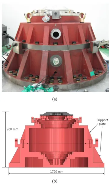
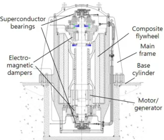
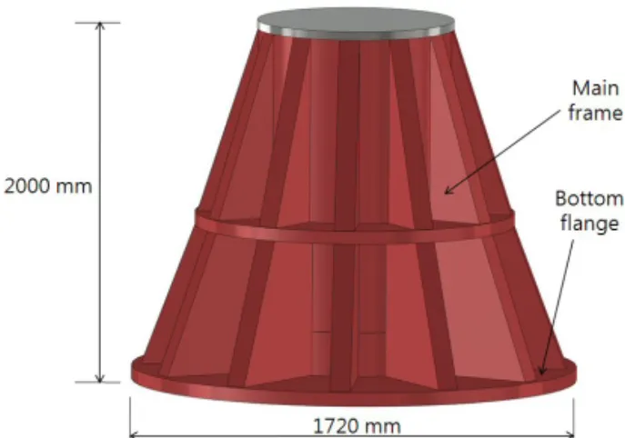
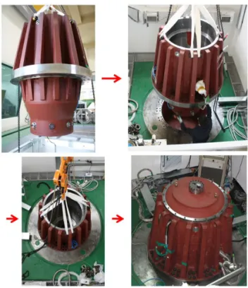
A superconductor flywheel energy storage system (SFES) is an electro-mechanical battery which transforms electrical energy into mechanical energy for storage, and vice versa. The 35 kWh class SFES is composed of a main frame, superconductor bearings, electro-magnetic dampers, a motor/generator, and a composite flywheel. The energy storing capacity of the SFES can be limited by the operational speed range of the system. The operational speed range is limited by many factors, especially the resonant frequency of the main frame and flywheel. In this study, a steel frame has been designed and constructed for a 35 kWh class SFES. All the main parts, their housings, and the flywheel are aligned and assembled on to the main frame. While in operation, the flywheel excites the main frame, as well as all the parts assembled to it, causing the system to vibrate at the rotating speed. If the main frame is excited at its resonant frequency, the system will resonate, which may lead to unstable levitation at the superconductor bearings and electro-magnetic dampers. The main frame for the 35 kWh class SFES has been designed and constructed to improve stiffness for the stable operation of the system within the operational speed range.

Keywords : superconductor, flywheel, energy, storage, stiffness, frequency

I. Introduction

A superconductor flywheel energy storage system (SFES) is an electro-mechanical battery with high

energy storage density, long life, and good environmental affinity. An SFES mainly consists of a pair of non-contacting high temperature superconductor (HTS) bearings that provide very low frictional losses, a composite flywheel with high energy storage density and mechanical strength, a motor/generator that transfers mechanical energy into

*Corresponding author. Fax : +82 42 865 5679 e-mail : [email protected]

(2)

electrical form and vice versa, and a vacuum chamber that minimizes windage losses. The HTS bearings, which offer dynamic stability without active control, are the key technology that distinguishes the SFES from other flywheel energy storage devices, and great effort is being put into developing this technology [1-4].

The energy storing capacity of the SFES can be limited by the operational speed range of the system.

All other conditions being equal, the wider the operational speed range, the larger the energy storing capacity of the SFES. The operational speed range is affected by many factors, especially the resonant frequency of the main frame and flywheel. While in operation, the flywheel excites the main frame, as well as all the parts assembled to it, causing the system to vibrate at the rotating speed. If the main frame, flywheel, or any other part of the system is excited at its resonant frequency, the system may oscillate at great amplitudes, which may lead to unstable levitation at the superconductor bearings and electro-magnetic dampers.

In this study, the main frame for the 35 kWh class SFES has been designed and constructed for stable operation of the system. Stiffness of the 35 kWh class SFES main frame was improved from the earlier 10 kWh class SFES main frame model, leading to a higher resonant frequency, which allows for stable operation within the operational speed range.

II. 10 kWh Class SFES main frame

A 10 kWh class SFES was built and tested at KEPCO Research Institute in 2010. The 10 kWh class rotor was a vertical axis open-core type flywheel, and the housings for the stators of the main parts were assembled to the main frame. The 10 kWh class SFES main frame was designed and built as shown in Fig. 1. Cast iron(FCD 450) was used to build the ф1720ⅹ980H main frame, and the cross-section of the frame was molded into a trapezoidal form and fixed at the bottom flange to

create a stable overall shape. Support plates were used to strengthen the main frame cylinder to increase stiffness while only slightly increasing weight. As a result, the resonant frequency of the 10 kWh class SFES main frame was increased with a slight increase in weight, leading to lower material and manufacturing costs.

(a)

(b)

Fig. 1. 10 kWh class SFES (a) main frame and (b) cross-sectional view.

The resonant frequency of the design for the 10

kWh class SFES main frame was simulated, as

shown in Fig. 2, before it was constructed. For the

boundary conditions, the anchor bolts at the bottom

flange were fixed to the ground, and the lower

(3)

surface of the main frame was frictionless with respect to the surface of the ground. The maximum rotational speed of the 10 kWh class rotor is 13,000 rpm, which is equal to 217 Hz. As shown in Fig. 2, the first and second bending modes of the 10 kWh class SFES main frame are 551 Hz and 555 Hz, respectively. The colors indicate the displacement at the respective frequency, which increases from blue to red. It can be seen that the bottom flange fixed to the floor does not move, while the top of the main frame shows the largest displacement. The first bending mode (551 Hz) is more than twice the maximum rotational speed, in other words, the 10 kWh class SFES main frame will not resonate due to the excitation vibration caused by the rotor within the operational speed range.

Fig. 2. Resonant frequency simulation of 10 kWh class SFES main frame.

III. 35 kWh Class SFES main frame

The 35 kWh class SFES, shown in Fig. 3, was designed according to the general specifications of Table 1. The system is a vertical axis inner rotor type, with a composite flywheel levitated by two superconductor bearings, two radial active magnetic dampers and one thrust active magnetic damper, and rotated by a motor/generator in the lower part of the flywheel.

Fig. 3. Cross-sectional view of 35 kWh class SFES.

Table 1. General specifications of 35 kWh class SFES.

Specification Value Unit

Stored energy 35 kWh

Specific Energy Density 32.5 Wh/kg Max. operating speed 12,000 rpm

sIp/It ratio 0.61 -

Added mass 160 kg

Flywheel 1.6 ton

Inner diameter 456 mm

Outer diameter 907.7 mm

Height 1,300 mm

Design Considerations for 35 kWh Class SFES main frame

To increase the storing capacity and size of a system, the dimensions of the system are usually scaled up.

But if the dimensions of the 10 kWh class SFES main

frame were simply scaled up, as shown in Fig. 4, to

match the size of the 35 kWh class rotor and stators,

the 35 kWh class SFES main frame would not provide

a stable structure in the operating speed range.

(4)

Fig. 4. Main frame scaled-up from 10 kWh class SFES frame.

The trapezoidal shape of the scale-up main frame does not provide enough stiffness, which results in a low resonant frequency. Compared to the 10 kWh class SFES main frame, the 35 kWh class SFES main frame is too tall and heavy, so much that no adjustments made within the trapezoidal shape would allow for a resonant frequency high enough for stable operation within the rotational speed range. When the bottom flange of the 35 kWh class SFES main frame is fixed to the ground, the height and weight of the main frame lower the resonant frequency while the support plates increase stiffness and resonant frequency. But the height and weight factor overshadow the increased stiffness due to the support plates, which makes the main frame more prone to bending at the excitation of a lower frequency.

Adjustments had to be made in the overall shape and fixing points of the main frame during the design stage of the 35 kWh class SFES main frame.

Design of 35 kWh Class SFES main frame

As shown in Fig. 5, the shape of the support plates, the number of support plates, the thickness of the support plates, the main frame wall thickness, the location of the flange fixed to the ground, the flange thickness and other dimensional factors were modified to increase the resonant frequency of the 35 kWh class SFES main frame.

The final design of the 35 kWh class SFES main frame is shown in Fig. 6. The upper and lower module

s are the parts where the main components, such as the superconductor bearing stators, motor/generator, active magnetic dampers, etc. are assembled. The main frame is strengthened by 16 triangular support plates on the upper and lower side each, while the frame is fixed to the ground at the flange located at the mid-part of the frame. The diameter of the ф1720ⅹ2400H 35 kWh class SFES main frame is equal to that of the 10 kWh class SFES main frame (Fig. 1(a)), while the height is more than two times larger. Locating the flange at the bottom, and thus fixing the lower part of the main frame would have caused the resonant frequency to drop drastically, but by fixing the mid-part of the main frame, the 35 kWh class SFES main frame resulted in a combination of two 10 kWh class SFES main frames, one right side up on the upper side and one upside down on the lower side, when considering dimensions and shape.

Fig. 5. 35 kWh class SFES main frame design factors.

Fig. 6. Final design of 35 kWh class SFES main frame.

(5)

(a)

(b)

Fig. 7. (a) Conical mode and (b) bending mode of 35 kWh class SFES main frame.

The resonant frequency of the 35 kWh class SFES main frame was simulated, and its results are shown in Fig. 7. The colors indicate the displacement during each vibration mode, with the displacement increasing from blue to red. The first resonant frequency is at 312.75 Hz, which is a conical mode, and the second frequency at 374.4 Hz, which is a bending mode. The maximum rotational speed of the 35 kWh class SFES is 12,000 rpm, or 200 Hz, which gives a 56% margin of safety over the operating range.

Construction of 35 kWh Class SFES main frame The 35 kWh class SFES main frame was manufactured by casting and precision machining, to

align the bores where the main components of the system are assembled. As shown in Fig. 8, the finished 35 kWh class SFES main frame was fixed at the mid-part flange to the ground, and then vacuum sealed for test operation.

Fig. 8. 35 kWh class SFES main frame assembly.

IV. Conclusions

In this study, a steel frame has been designed and constructed for a 35 kWh class SFES. All the main parts, their housings, and the flywheel are aligned and assembled on to the main frame. The main frame for the 35 kWh class SFES has been designed and constructed to improve stiffness, and as a result increase resonant frequency, for the stable operation of the system within the operational speed range.

Acknowledgments

This work was financially supported by Korea

Energy Technology Evaluation and Planning.

(6)

References

[1] J. R. Hull, “Superconducting bearings”, Supercond.

Sci. Technol., vol. 13, p.R1 (2000).

[2] Nagaya, S. et al., “Study on high temperature superconducting magnetic bearings for 10 kWh flywheel energy storage system”, IEEE Trans. Applied Supercon., vol 11, pp. 1649-1652 (2001).

[3] Coombs, T. et al., “Superconducting magnetic bearings for energy storage flywheels”, IEEE Trans. Applied Supercon., vol. 9, pp. 968-971 (1999).

[4] Ichihara, T. et al., “Application of superconducting magnetic bearings to a 10 kWh-class flywheel energy storage system”, IEEE Trans. Applied Supercon., vol.

15, pp. 2245-2248 (2005).

수치

Fig. 1. 10 kWh class SFES (a) main frame and (b)  cross-sectional view.
Fig. 2. Resonant frequency simulation of 10 kWh class  SFES main frame.
Fig. 4. Main frame scaled-up from 10 kWh class SFES  frame.
Fig. 8. 35 kWh class SFES main frame assembly.

참조

관련 문서

 The Dutch physicist Pieter Zeeman showed the spectral lines emitted by atoms in a magnetic field split into multiple energy levels...  With no magnetic field to align them,

Modern Physics for Scientists and Engineers International Edition,

If both these adjustments are considered, the resulting approach is called a bootstrap-BC a -method (bias- corrected-accelerated). A description of this approach

③ A student who attended Korean course at KNU Korean Language Program and holds TOPIK Level 3 or a student who completed Korean course Level 4 at the KNU Korean Language

Five days later, on 15 January 1975, the Portuguese government signed an agreement with the MPLA, FNLA and UNITA providing for Angola to receive its independence on 11

· 50% exemption from tuition fee Ⅱ for the student with a TOPIK score of level 3 or higher or completion of level 4 or higher class of the Korean language program at the

○ Main activities: participation in the main international events in Gangwon province and support for interpretation when necessary... □

Our main contribution consists in the elevation of the DTW power of alignment from the lowest level (Class A, non-periodic time series) to the highest level (Class