Korean J. Mater. Res.
Vol. 25, No. 2 (2015)
107
Preparation and Properties of Y
2O
3-Doped ZrO
2Films on Etched Al Foil by Sol-Gel Process
Fei Chen and Sang-Shik Park
†School of Nano Materials Engineering, Kyungpook National University, Sangju 742-711, Korea (Received December 11, 2014 : Received in revised form February 5, 2015 : Accepted February 5, 2015)
Abstract
The oxide films formed on etched aluminum foils play an important role as dielectric layers in aluminum electrolytic capacitors. Y2O3-doped ZrO2 (YZ) films were coated on the etched aluminum foils by sol-gel dip coating, and the electrical properties of YZ-coated Al foils were characterized. YZ films annealed at 450oC were crystallized into a cubic phase, and as the Y2O3 doping content increased, the unit cell of ZrO2 expanded and the grain size decreased. The etch pits of Al foils were filled by YZ sol when it dried at atmospheric pressure after repeating for several times, but this step could essentially be avoided when being dried in a vacuum. YZ-coated foils indicated that the specific capacitance and dissipation factor were 2-2.5µF/cm2 and 2-4 at 1 kHz, respectively, and the leakage current and withstanding voltage of films approximately 200 nm thick were 5× 10⁻⁴A at 21 V and 22 V, respectively. After being anodized at 500 V, the foils exhibited a specific capacitance and dissipation factor of 0.6-0.7µF/cm2 and 0.1-0.2, respectively, at 1 kHz, while the leakage current and withstanding voltage were 2× 10⁻⁴- 3× 10⁻⁵A at 400 V and 420-450 V, respectively. This suggests that YZ film is a promising dielectric that can be used in high voltage Al electrolytic capacitors.Key words
aluminum, sol-gel coating, YZ film, electrolytic capacitor, capacitance.1. Introduction
Aluminum electrolytic capacitors are widely used in electric and electronic systems. With the rapid development of the electric industry and the increasing demand for small capacitors with high capacitance, extensive studies have been performed to increase the capacitance.
1,2)It is well known that the capacitance can be increased by in- creasing the relative dielectric constant and effective sur- face area. Although the surface area is enlarged greatly by the electrochemical etching of Al foil, the development of high-capacitance capacitors is very difficult because the enlargement of the surface area by the etching process is faced with a limit.
3)Anodized aluminum oxide, Al
2O
3,has been used as a dielectric material in aluminum electrolytic capacitors. The dielectric constant of Al
2O
3is approximately 8-9. Thus, the application of high dielectric materials to replace alumina is a possible way to improve the capacitance. Until now, substantial research has been performed on the fabrication of composite oxide films by forming high dielectric constant(high-k) materials into
etched Al foil before anodizing. It has been found that the specific capacitance can be improved by the com- posite oxide films, such as Al
2O
3-(ZrO
2, SiO
2, (Ba
0.5Sr
0.5) TiO
3, Bi
4TiO
12, Nb
2O
5, and TiO
2), to a certain degree.
4-9)These studies showed that composite oxide films formed by anodizing have a higher specific capacitance than those composed of Al foil without coating. However, the specific capacitance of the composite oxide films was only approximately 20-30 % higher than that of the anodized Al foil, owing to the lower dielectric constant of the Al
2O
3film. The dielectric constant of high-k materials was not largely reflected in the capacitance of the oxide-coated foils. Moreover, most previous research has focused on the coating not of etched Al foil but of Al plane foil. The uniform coating of oxide films on the inner walls of narrow and deep etch pits is critical for commercial applications.
In this study, the sol-gel dip process was applied for the preparation of Y
2O
3doped ZrO
2(YZ) films on etched Al foil. ZrO
2is a promising high- material owing to its high dielectric constant(22-25) and wide band gap(5.1-
†Corresponding author
E-Mail : [email protected] (S.-S. Park, Kyungpook Nat'l Univ.)
©Materials Research Society of Korea, All rights reserved.
This is an Open-Access article distributed under the terms of the Creative Commons Attribution Non-Commercial License (http://creative- commons.org/licenses/by-nc/3.0) which permits unrestricted non-commercial use, distribution, and reproduction in any medium, provided the original work is properly cited.
2. Experimental procedure 2.1 Sample preparation
The sol was prepared by mixing zirconium(IV) butoxide (Zr(OC
4H
9)
4, 80 wt% in 1-butanol, Sigma-Aldrich, USA), yttrium nitrate hexahydrate(Y(NO
3)
3·6H
2O, 99.8 %, Sigma- Aldrich, USA), and 2-methoxyethanol(CH
3OCH
2CH
2OH, anhydrous, 99.8 %, Sigma-Aldrich, USA) with acetic acid (CH
3COOH, 99.7 %, Daejung Chemicals & Metals, Korea) as a complexing agent. The molar ratio of acetic acid to zirconium was 6. After stirring for 1 h, nitric acid(HNO
3, 70 %, Sigma-Aldrich) was added as an acid catalyst to avoid hydroxide precipitation. 4-20 mol% Y
2O
3- doped ZrO
2sols were prepared by the above process, and a clean and transparent precursor sol was obtained.
Etched Al foils were used as substrates. The thickness, tunnel diameter, and pit density of the etched Al foils were approximately 110 μm, 1-2 μm, and 2.0 × 10
7cm
−2, respectively. The dip-coating process was employed to deposit YZ thin films. The specimens were immersed in sol for 5 min and withdrawn at a rate of 0.5 mm/s, followed by drying at 100
oC for 30 min. The samples were annealed at 450
oC for 30 min. The flow chart of the sol preparation and coating process is presented in Fig. 1. In order to identify the anodizing behavior after the coating of the YZ films, the foils were anodized up to 500 V with 50 mA/cm
2constant current in a H
3BO
3100 g / H
2O 1 L solution.
2.2 Characterization of samples
The crystal structure of the YZ films was analyzed by the X-ray diffraction(XRD, X’pert Pro, PANalytical, Netherlands) method using Cu k α radiation. The mor- phologies and thickness of the films were identified by an optical microscope(OM, BX-60, Olympus, Japan) and field emission scanning electron microscopy(FESEM, JSM-6700F, Jeol, Japan). The capacitance and dissipation factor for each specimen were measured using an imped- ance-gain phase analyzer(4194A, Hewlett-Packard, USA) in water (1 L) and an ammonium pentaborate(NH
4B
5O
8·
4H
2O, 80 g, 98 % Junsei Chem., Japan) mixture. The electric properties, such as the withstanding voltage and leakage current, were characterized by a source meter (2410, Keithley, USA) in water (1 L) and a boric acid (H
3BO
3, 70 g, 99.5 %, OCI, Korea) mixture. The with- standing voltage of the Al foil was measured by loading a constant current density of 0.2 mA/cm
2.
3. Results and discussion
The preparation of crack-free films is essential for the improvement of electrical properties such as the leakage current and withstanding voltage. In order to determine the Y
2O
3doping concentration, 4-20 mol% YZ sols were prepared and coated on plane Al foils. Fig. 2 shows the optical microscopy images of annealed YZ films with a varying Y
2O
3doping content. The films were obtained by repeating the coating and annealing stages four times.
The pure ZrO
2film of Fig. 2(a) exhibits many cracks, but the crack density decreases as the Y
2O
3doping con- centration increases. The ZrO
2film of Fig. 2(d), with an Y
2O
3concentration greater than 12 mol%, exhibits many wrinkles because of the high viscosity.
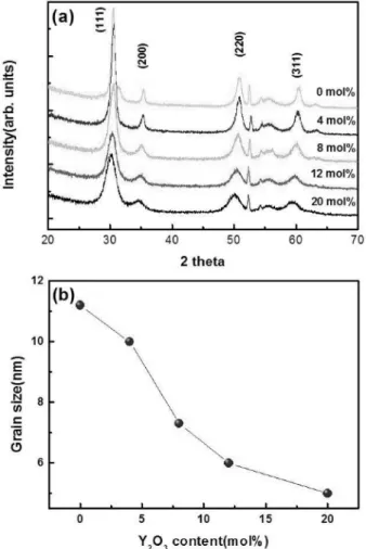
Fig. 3(a) shows the XRD patterns of ZrO
2films with different Y
2O
3doping concentrations. The XRD patterns indicate that the films have a cubic structure. As the Y
2O
3content increases, the peaks of the YZ films shift toward a lower angle. The peak shift indicates that Y
2O
3substitutes partially for ZrO
2in the crystal lattice and then the lattice parameter of the films increased. As ex- pected, owing to the larger ionic radius of Y
3+(0.09 nm) with respect to Zr
4+(0.072 nm), the introduction of Y
3+ions into the ZrO
2matrix induces an expansion of the
Fig. 1. Flow chart showing the stepwise method of preparation of Y2O3-doped ZrO2 sol and films.unit cell dimensions. The full width at half maximum (FWHM) tends to increase as the Y
2O
3content increases.
Fig. 3(b) shows the variation of the grain size with the Y
2O
3content. The grain size (D) of the YZ films was estimated using Debye Scherrer’s formula
13):
,
where λ is the wavelength of the X-ray, and β is the full width at half maximum of the (111) peak of the XRD pattern. The grain size decreases as the Y
2O
3doping content increases. Considering the crack formation and grain size, the authors selected an 8-mol% Y
2O
3doping sol for the following coating experiments.
Fig. 4 shows SEM images of YZ-coated Al foils under different drying conditions after coating four times. Figs.
4(a), (b), and (c) are surface images of the etched foil without coating, the foil dried at atmospheric pressure, and the foil dried in a vacuum after coating, respectively.
DC etching has been performed to obtain a tunnel-type etch pits in aluminum foils for high-voltage capacitors.
14)To enhance the surface quality and reduce the roughness of DC etched Al foil, electropolishing in a mixture of perchloric acid and acetic acid at 20 V was performed.
The etched foil comprises single etch pits and merged etch pits. The diameters of the etch pits range roughly from 1 to several μm. The foils dried at atmospheric pre- ssure(Fig. 4(b)) exhibited a blockage of the etch pits by the YZ sol, which prevented the etch pits from additional coating and caused a decrease in the specific capacitance.
However, the foils dried in a vacuum(Fig. 4(c)) did not exhibit any blockage in the etch tunnel inlet. In order to observe the cross section(replica image) of Fig. 4(d), the samples were mounted with epoxy resin, and their sur- faces were polished. Then, the aluminum was dissolved by placing the samples into a potassium hydroxide(KOH)
solution. The replica image of Fig. 4(d) shows that the YZ sol was well coated on the etch tunnels 25-35 μm in length.
Fig. 5 contains SEM images of the Al foils coated with different coating times. The surface images of Figs. 5(a), (b), and (c) depict foils coated 4, 8, and 12 times, respectively. As the coating times increases, the thickness of the coating layer increases, and the diameter of etch pit decreases. The small tunnels are blocked after coating 12 times. Fig. 5(d) is a surface replica image of the Fig.
5(b) foil. The YZ film coated on the inner walls of the Al etch pits is approximately 100-200 nm in thickness, exhibiting non-uniform thickness among the pits. In addition, the specimen coated 12 times exhibited only a small increase in thickness compared with that coated 8 times, which exhibited an increase of 150-230 nm. How- ever, the thickness of the YZ film coated on the plane foil exhibited a clear increase of approximately 25 nm/
coating times. Therefore, it is necessary to design a new dip process to coat the films with uniform thickness on deep etch pits. The design of the new dip coating process is currently in progress.
D 0.94λ
β2θcosθ ---
=
Fig. 3. (a) XRD patterns of ZrO2 films and (b) grain size variation with respect to Y2O3 doping content (0-20 mol%).
Fig. 2. Optical microscopy images of ZrO2 films with Y2O3 doping content: (a) 0 mol%, (b) 4 mol% (c) 8 mol%, and (d) 12 mol%.
Fig. 4. SEM images of YZ-coated Al foils under different drying conditions: (a) Al etched foil without coating, (b) foil dried at atmospheric pressure and (c) in a vacuum, and (d) cross-section replica image of (c) sample.
Fig. 5. SEM images of YZ-coated Al foils with different coating times: (a) 4 times, (b) 8 times, (c) 12 times; (d) polished surface(replica) of (b) sample.
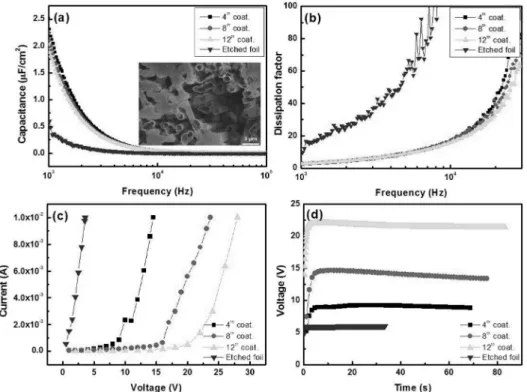
Fig. 6(a) and (b) indicate the capacitance and dis- sipation factor with respect to the frequency of the YZ- coated foils. The specific capacitance( μF/cm
2) for Fig.
6(a) was calculated using the apparent surface areas of the foils. The dielectric and electric properties of etched foil are attributed to natural oxide on etched Al foil. The
Fig. 6. Dielectric and electric properties of YZ film: (a) capacitance, (b) dissipation factor with frequency, (c) current-voltage(I-V), and (d) withstanding voltage(V-T) properties.Fig. 7. Dielectric and electric properties of YZ-coated Al foils anodized at 500 V: (a) current-voltage(I-V), (b) withstanding voltage(V-T) properties, (c) capacitance, and (d) dissipation factor with respect to frequency.
standing voltage(V-T) properties, respectively. With the increase in coating times, the withstanding voltage in- creases, and the leakage current decreases. The leakage current and withstanding voltage of the films with a thickness of ~200 nm are 5 × 10
−4A at 21 V and 22 V, respectively. In order to apply these results to a high- voltage capacitor, it is necessary to improve the leakage current and withstanding voltage of the YZ-coated foils.
For the improvement of the leakage current and with- standing voltage, the YZ-coated samples were anodized at 500 V, and then the electrical properties of the foils were analyzed again. The SEM image of Fig. 7(a) shows the morphology of YZ film anodized up to 500 V after coating 8 times. Figs. 7(a) and (b) show that the leakage current decreases significantly and the withstanding voltage increases above 420 V. The anodized foils exhibit a leakage current of 2 × 10
−4− 3 × 10
−5A at 400 V and a withstanding voltage of 420-450 V. This is the reason that Al
2O
3anodic oxide is formed between the YZ film and Al foil. During the anodizing of the Al foil, the ratio of the oxide thickness to the oxide formation voltage is approximately 0.8-1.0 nm/V.
15)After anodizing at 500 V, the capacitance and dissipation factor of the foils de- crease remarkably. The decrease of capacitance with fre- quency can be caused by a decrease in the space-charge polarization, which has a major role in contributing to the permittivity of anodically derived materials at a low frequency.
16)The specific capacitance and dissipation factor of foils are 0.6-0.7 μF/cm
2and 0.1-0.2, respec- tively, at 1 kHz. These results imply that forming a thick Al
2O
3film incurs a decrease in the capacitance and dissipation factor.
4. Conclusions
Y
2O
3-doped ZrO
2films were coated on etched Al foils by the sol-gel dip method for application as a dielectric material of Al electrolytic capacitors. YZ films annealed at 450
oC exhibited a cubic structure. The Y
2O
3doping content had an influence on the grain size and crack
anodizing. Overall, the YZ-coated Al foil is a suitable material for Al electrolytic capacitors.
Acknowledgement
This research was supported by a grant(13RTRP- B067917-01) from railroad technology research program funded by Ministry of Land, Infrastructure and Transport of Korean government.
References
1. R. S. Alwitt, H. Uchi, T. R. Beck and R. C. Alkire, J.
Electrochem. Soc., 131, 13 (1997).
2. H. Takahashi and M. Nagayama, Electrochim. Acta, 23, 279 (1978).
3. S. Park and B. Lee, J. Electroceram., 13, 111 (2004).
4. K. Watanabe, M. Sakairi, H. Takahashi, S. Hirai and S.
Yamaguchi, J. Electroanal. Chem., 473, 250 (1999).
5. K. Watanabe, M. Sakairi, H. Takahashi, K. Takahiro, S.
Nagata and S. Hirai, J. Electrochem. Soc., 148, B473 (2001).
6. Y. Xu, Ceram. Int., 30, 1741 (2004).
7. X. Du and Y. Xu, Surf. Coat. Technol., 202, 1923 (2008).
8. Z. Feng, J. Chen, R. Zhang and N. Zhao, Ceram. Int., 38, 3057 (2012).
9. J. Liu, Q. Guo, M. Yu, S. Li and L. Yao, ECS J. Solid State Sci. Technol., 2(3), N55 (2013) .
10. D. K. Fork and D. B. Fenner, Appl. Phys. Lett., 57, 1137 (1990).
11. R. H. French, S. J. Glass, F. S. Ohuchi, Y. N. Xu and W.
Y. Ching, Phys. Rev., 49, 5133 (1994).
12. S. H. Jeong, I. S. Bae, Y. S. Shin, S. B. Lee, H. T. Kwak and J. H. Boo, Thin Solid Films, 475, 354 (2005).
13. B. D. Cullity, Elements of X-Ray Diffraction, 2nd edition, Addison Wesley, Reading, MA, 1978.
14. Z. Hen and Z. Weibin, Mater. Sci. Eng., B3, 479 (1989).
15. H. Takahashi, C. Ikegami and M. Seo, J. Electron Microsc., 40, 101 (1991).
16. W. D. Kingery, H. K. Bowen and D. R. Uhlmann, Introduction to Ceramics, 2nd edition, Wiley, NY, 1976.