−
181
−결정성 탄소의 산처리가 고분자연료전지의 성능과 내구성에 미치는 영향 평가
오형석·한학수·김한성*
연세대학교 화공생명공학과 (2009년 5월 13일 접수 : 2009년 5월 25일)
Effect of Acid Treatment of Graphitized Carbon on Carbon Corrosion in Polymer Electrolyte Membrane Fuel Cells
Hyung-Suk Oh, Haksoo Han, and Hansung Kim*
Dept. of Chemical and Biomolecular Engineering, Yonsei University 134 Shinchon-Dong, Seodaemun-gu, 120-749 Seoul, Korea
(Received May 13, 2009, Accepted May 25, 2009)
초 록
carbon nanofiber (CNF)
의표면을질산과 황산을사용하여 산화시킨후백금촉매를modified
polyol method
로담지시켰다.
산처리 시간이길어질수록탄소표면에산소작용기의양이증가했으며그결과백금담지량이증가하고분산도가향상되었다
. CNF
의산처리시간이전기화학적부식특성에미치는영향을평가하기위해서단위전지형태에서
1.4 V
의정전압조건을30
분간 인 가하였으며이 때발생한CO
2 의 양을on-line mass spectrometry
로 측정하였다.
실험 결과산처리한
CNF
를 사용한Pt/CNF
촉매가산처리하지않은CNF
를 담체로사용한경우보다CO
2발생량이많았으며산처리시간이증가할수록CO
2발생량이증가하였다.
부식실험이후 성능감소의폭은카본부식이증가할수록증가하였다
.
이는CNF
에대한산처리가 촉매담지에는유리할수있으나전기화학적카본부식을가속화시키는결과를초래하여결과적으로연료전지 내구성을 저하시키는 요인이 될 수 있는 것으로 사료된다
.
Abstract:
Pt catalyst was adsorbed on Carbon nanofiber (CNF) by modified polyol method after acid treatment of the carbon support with HNO
3and H
2SO
4. As the time for acid treatment increases, more oxygen functional groups on carbon surface were produced which improve the loading amount and dispersion of Pt catalyst on carbon supports. In order to inspect the effect of CNF acid treatment time on electrochemical corrosion, constant potential of 1.4 V was applied to a single cell for 30 min and the amount of CO
2emitted was monitored with on-line mass spectrometry. According to the results of our experiment, more CO
2was produced with Pt/
oxidized-CNF catalyst in compared to that with unoxidized-CNF. Increasing acid treatment time also induces the more CO
2emission. Besides, performance degradation after corrosion test expanded with severer carbon corrosion. From the observed results, it can be concluded that the acid treatment of CNF is beneficial to catalyst loading, but it also is a significant factor declining the fuel cell durability by accelerating electrochemical oxidation of carbon support.
Keywords :
Carbon nanofiber, Chemical oxidation, Durability, Carbon corrosion, PEM fuel cell
*E-mail: [email protected]
1. 서 론
결정성 탄소인
Carbon nanotube(CNT), Carbon nanofiber(CNF)
는뛰어난전기적,
1)물리적2)성질때문에 촉매담체로사용하기위한연구가활발히이루어지고 있다.
3-5)특히연료전지촉매담체에적용될경우백금촉매의활용도를높여주고백금과담체간의결합력을 증가시켜성능이향상된다는연구결과가보고되고있 다
.
6-9)또한탄소담체의전기화학적부식이연료전지의성능 저하의 주요 원인 중 하나로 알려지면서 부식 저항성에 강한
CNT
와CNF
를촉매 담체로사용하는연구가진행되고있다
.
10-12)그러나CNT
와CNF
표면의발수성 때문에 극성 용매에서 뭉치는경향성을 가져 고비율
,
고분산의백금담지촉매제조에어려움이있다.
13)이런문제점을개선하기위해탄소표면을산화시켜작용 기를붙이는방법이사용되고있으며플라즈마와공기
,
강산을 사용하는방법이활용되고 있다
.
그러나플라즈마와공기를사용한방법은
CNT
와CNF
의표면구조를 파괴할정도의 강한산화 반응으로촉매 담체에 적용시키기적합하지않기때문에대신산처리방법이 널리 사용되고있다
[14,15].
산처리방법에사용되는강산은질산
,
황산혹은질산과황산혼합용액이사용되며탄소표면에카르복실기
(-COOH),
히드록시기
(-OH),
카보닐기(>C=O)
와같이산소를포함한 작용기를형성시키는역할을한다.
16)탄소표면에형성된작용기는친수성을증가시켜극성용매에서용해도를증가 시킨다
.
17)또한탄소표면에생성된작용기는백금이온 들의교착지점을제공함으로서고비율,
고분산의백금담지촉매를얻을수있다
.
18-20)이런장점으로CNT
와CNF
를촉매담체로사용할경우금속입자를담지하기전산처리과정이이루어진다
.
하지만 이러한산처리 과정은입자담지에효과적일수있으나오히려카본부 식에대한내구성을저하시킬가능성이크다.
본연구실의기존연구에따르면연료전지촉매의탄소부식은가습 양에영향을받으며가습양이증가할수록탄소담체 부식이더활발하게진행된다
.
21)탄소부식메커니즘(1)
에서볼수있듯이탄소를부식시켜이산화탄소를생산 해내는산소는물에서공급된다
.
따라서탄소담체가물과 접촉하는발수성의정도는탄소의전기화학적부식과 밀접한관계가있으며발수성이높은CNT
와CNF
의 산처리과정 또한탄소부식에영향을미칠수있다. C + 2H
2O
→CO
2+ 4H
++ 4e
-E = 0.207 V
SHE(1)
본연구에서는높은결정성을갖는
carbon nanofiber
(CNF)
를산처리시간을달리하여표면의산소작용기의양을조절하였고이를이용한
Pt/CNF
촉매를제조하였다.
그리고
on-line mass spectrometry
를사용하여전기화학적부식실험동안발생한
CO
2양을실시간으로측정함 으로써전기화학적탄소부식을정량평가하였다.
22)이러한결과를바탕으로
PEMFC
용촉매담체로결정성탄소인CNF
의산처리가내구성에미치는영향을확인하려한다.
2. 실험방법
고결정성탄소 담체인
herring-bone type
의CNF
가 황산과질산 혼합용액80
oC
에서교반 시간(0, 1, 3, 4, 8, 16
시간)
을달리하여산처리되었다.
산처리된CNF
를 담체로 사용하여 상기연구된modified polyol
방법으로
Pt/CNF
촉매를제조하였다.
23) 결정성탄소인CNF
의산처리시간이탄소부식에미치는영향을비교하기위해서
membrane electrode assembly (MEA)
를제조하여부식 평가하였다
. Johnson Matthey
사의40 wt%
Pt/C
를연료전극촉매로선택하고산처리된CNF
를담체로사용한 백금담지촉매를 환원전극촉매로사용 하였으며 촉매를
Isopropanol, 5 wt% Nafion
용액과섞어 슬러리를 제조하고
nafion 212
전해질막에Pt
loading
양이0.4 mg/cm
2가되도록스프레이하였다.
제 조된5 cm
2MEA
는셀에체결한뒤부식테스트전후로각각 주어진 조건에서 단위전지 성능곡선
, cyclic
voltammetry (CV)
그리고 임피던스를측정하였다.
단 위전지성능은산화전극에수소150 ml/min,
환원전극에 산소150 ml/min
을흘려주고상압,
셀온도75
oC
에서측정하였다
.
단위전지의 성능을 측정한 후 임피던스실험을시행하였다
.
그후CV
실험을하기전에약30
분 동안 질소 기체를 흘려주었다.
질소 처리가 끝난 뒤50 mV/s
의주사속도로0.05~1.2 V
SHE 범위에서CV
를측정하고부식평가를위해가습과셀온도를
90
oC
로변경하였다
.
그후mass spectrometer
를cathode
에연결하 고기체유량을각각산화전극20ml/min (
수소),
환원전극30 ml/min (
질소)
으로 고정시키고1.4 V
의constant potential
을환원전극에30
분동안인가하여탄소가부 식할수있는환경을부여하였다.
부식평가중시간에 따른이산화탄소 발생량은mass spectrometry
를통해 실시간측정하였다.
부식평가후CV,
단위전지성능곡선과임피던스를 측정하여부식 전과 비교하였다
.
산처리시간에따른
CNF
의표면산화정도를평가하기 위해CNF
만의CV
를0.5 M H
2SO
4전해질,
주사속도5 mV/s,
주사구간0~1.0 V
SHE조건에서실시 하였다.
탄소의표면을분석하기위해
XPS
분석법을사용하였다
.
분석 조건은100 W (15 kV, 10 mA), AlKa (1486.6 eV), < 10
−10mbar
이며 결합 에너지(BE)
는C 1 s
피크를284.6 eV
로하여보정 하였다. CNF
에담지된백금촉매의분산도를확인하기위해고해상도 전자 현미경인
JEM-3010 (JEOL)
기종을 사용하였다.
백금의입자크기를측정하기위해
XRD
분석을하였 으며측정범위20~90
o, 2
o/min
의조건에서실시하였다.
3. 결과 및 고찰
결정성
CNF
탄소의산처리시간에따른표면산화물생성을확인하기위해
CNF
의CV
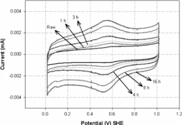
를실시하여그결과를Fig. 1
에나타내었다. CNF
의산처리시간은0, 1, 3, 4, 8, 16
으로 달리하였으며CV
의주사 속도는5 mV/s
조건에서 실시 하였다
. CV
그래프의0.6 V
영역에서나타나는전류피크는탄소표면에형성된산화물에의해 나타나며 이 부분을
Hydroquinone-quinone (HQ-Q)
영역이라 한다
.
24,25)HQ-Q
영역의 전류 피크는아래메커니즘에 의해나타난다
.
26)C = O + e
−+ H
+→C
−OH (2)
HQ-Q
영역의전류피크가증가하는것은탄소표면산화물의양이증가했기때문이며산처리시간이증가
할수록
HQ-Q
영역의전류피크가증가하는것을통해표면 산화물의 양이증가 하였다는 것을 확인 할수 있다
.
27)XPS
분석은탄소표면의산소와탄소의비율을 측정할수있어폭넓게활용되고있는분석방법이다.
본연구에서는산처리시간에따른
CNF
의표면산화물을정량평가하기위해
XPS
분석을진행하였으며결과값을Table 1
에나타내었다. 16
시간산처리한CNF
는산처리 하지않은CNF
에비해산소비율이4
배증가하였다.
이 결과를통해산처리시간이증가할수록탄소의산소 비율이증가하였으며탄소표면의산소작용기농도의 증가로탄소표면의친수성이증가하게된다.
28)산처리된
CNF
를 담체로사용하여modified polyol process
를통해백금을담지하였다.
제조된Pt/CNF
의백금입자크기및분산도를확인하기위해
HR-TEM
이미지를 촬영 하였으며
Fig. 2
에 나타내었다. HR-
TEM
을통해확인된백금입자크기는산처리시간에관계없이
2.5 nm
로큰차이를보이지 않았다.
이는polyol process
과정에서생성되는glycolate anion
이stabilizer
역학을해주기때문으로판단된다
.
29)그러나백금이담체에 고르게담지되어있는정도를나타내는분산도의경우산 처리시간이증가할수록좋아지는것을확인할수있다.
이러한결과는산처리시간이증가할수록카르복실기
(
−COOH),
히드록시기(
−OH),
카보닐기(> C = O)
와같 은표면산화물의양이 증가하고이런표면산화물들 이백금의교착지점역할을했기때문으로판단된다.
Pt/CNF
의백금입자크기를좀더정확히측정하기위해XRD
분석을하였으며이를Fig. 3
에나타내었다. XRD pattern
의2
θ= 67
o 영역의Pt(220) peak
를scherrer formular
에적용시켜백금 입자크기를계산하였다.
30)XRD
를통해계산된백금입자크기는산처리하지않은raw Pt/CNF
가2.0nm,
산처리한Pt/CNF
모두1.8 nm
로HR-TEM
이미지에서확인된것과같이백금입자크기는비슷한것을 확인할수 있었다
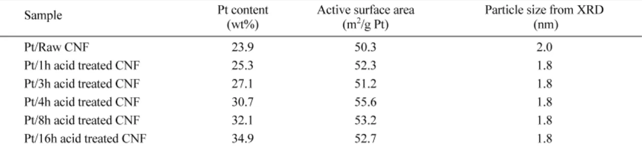
. Pt/CNF
촉매의백금담지율과촉매의활성면적을측정하기위해
ICP
와CV
실험을진행하였고그결과를
Table 2
에나타내었다.
ICP
분석을통한 백금 담지량은Raw Pt/CNF
의 경우23.9 wt%, 16
시간산처리한Pt/CNF
의경우34.9 wt%
로산처리시간에따라백금비율이증가하였으며
40 wt%
의 목표값을기준으로각각60%
에서87%
로수율이증가 하였다. CV
실험을통해측정된백금촉매의유효활성 면적은산처리조건에관계없이약50 m
2/g Pt
로비슷하게측정되었다
.
이는XRD
와HR-TEM image
분석을 통해확인할수있듯이CNF
에담지된백금의입자크 기가비슷하기때문에백금의단위질량당활성면적이 유사하게측정되었다.
산처리시간을달리한
CNF
를담체로사용한Pt/CNF
를 공기조건에서성능평가하였고그결과를Fig. 4
에나Fig. 1. Cyclic voltammograms of the CNFs with different acid treatment time. Voltage scan rate =5mV/s, treatment time= 0, 1, 3, 4, 8, 16 hours.
Table 1. Evaluation of oxygen and carbon content in the surface of CNFs as a function of acid treatment time using XPS
Sample O composition
(%) C composition (%)
Raw CNF 1.65 98.35
1h acid treated CNF 3.55 96.45
3h acid treated CNF 4.62 95.38
4h acid treated CNF 4.94 95.06
8h acid treated CNF 6.12 93.88
16h acid treated CNF 7.04 92.96
Fig. 2. HR-TEM images of Pt particles on the CNFs with different acid treatment time : (a) 0 h, (b) 1 h, (c) 3 h, (d) 4 h,
(e) 8 h, (f) 16 h.
타내었다
. 16
시간산처리한Pt/CNF
가0.6V
에서0.886A/cm
2로
raw Pt/CNF
의0.784 A/cm
2보다높게측정되었다.
이러한 결과는 두 촉매의 백금 입자 크기가 유사한 조건하에서
16
시간산처리한Pt/CNF
의백금담지율이34.9wt%
로산처리하지않은raw Pt/CNF
의백금담 지율23.9wt%
보다높기때문에16
시간산처리한촉매의 전극 두께가얇아지게되어성능이 향상된것으로 파 악된다.
CNF
의산처리조건에따른연료전지촉매의내구성을파악하기위해전기화학적부식평가가진행되었다
.
탄소담체의전기화학적부식메커니즘은반응식
(1)
과같이최종생성물로
CO
2 가발생하기때문에CO
2 를직접 정량 측정 함으로써 탄소의부식 정도를평가 할 수 있다.
부식실험시발생한CO
2양과부식실험전후의MEA
성능곡선
, CV
그리고임피던스를측정하였고그결과를Table 3
에정리하였다. Fig. 5
는Pt/CNF
촉매의부식평가중발생한이산화탄소의양을
on-line mass spectrometer
를사용하여실시간정량평가한그래프이다
.
산처리가되지않은
raw Pt/CNF
촉매의경우부식실험이이루어진
30
분 동안 이산화탄소의 발생량이18
μL
발생하였다
.
반면CNF
의산처리가16
시간이루어진Pt/CNF
촉매의 경우 이산화탄소 발생 양이
186
μL
로raw Pt/
CNF
와비교해10
배증가 한것을확인 할수있다.
Fig. 6
는부식평가전후의단위전지성능을나타낸결과 이다.
부식평가전후의단위전지성능은Table 3.
에나타냈으며각샘플의초기성능값은매우유사하여대표 값을갖는한그래프로나타내었다
.
초기성능이유사한 이유는산소분위기에서측정되었기때문에물질전달저항의 영향을받지않기때문인것으로보인다.
부식의정도는부식평가전후셀전압
0.6V
에서의전류밀도감소율을통해평가하였다
. raw Pt/CNF
촉매의경우10.0%
의성능감 소를보인반면이산화탄소발생량이가장많았던16
시간산처리한
Pt/CNF
의경우61.0%
의성능감소를보였다.
부식평가전후백금촉매의활성표면적
(S
pt)
변화와저항 변화를측정하기위해단위전지상에서CV
와임피던스를 실시한결과부식경향과일치하는결과를얻었다.
따라서 산처리시간이증가함에따라카본부식이증가하는것으로 판단된다.
하지만이러한결론을내리기전에카본부식의 증가가 촉매 담지량의 증가로인한 결과인지 확인할 필요가있다.
일반적으로연료전지촉매의백금담지율이증가할수록탄소담체의부식성이증가하는것으로알
려져있기때문이다
.
31-33)이점을확인하기위해서산처리Fig. 3. XRD patterns of Pt particles on the CNFs with different acid treatment time.
Fig. 4. Polarization curves of MEA using H
2/air at 1 atm with respect to the acid treatment time on CNFs : (a) Raw Pt/CNF, (b) 16 h acid treatment Pt/CNF
Table 2. Properties of Pt/CNF with different acid treatment time
Sample Pt content
(wt%) Active surface area
(m
2/g Pt) Particle size from XRD (nm)
Pt/Raw CNF 23.9 50.3 2.0
Pt/1h acid treated CNF 25.3 52.3 1.8
Pt/3h acid treated CNF 27.1 51.2 1.8
Pt/4h acid treated CNF 30.7 55.6 1.8
Pt/8h acid treated CNF 32.1 53.2 1.8
Pt/16h acid treated CNF 34.9 52.7 1.8
시간이다른
CNF
에백금담지율을동일하게하여부식 평가를진행하였다. Fig. 7
은16
시간산처리된CNF
를 담체로사용하여각각백금을34.9 wt%
와27.4 wt%
담 지한촉매와3
시간산처리한CNF
에27.1 wt%
백금을담지한촉매의부식평가결과를나타낸그래프이다
.
동 일한담체내에서는 백금 담지량이증가 할수록카본 부식이증가하였다.
하지만약27 wt%
로거의동일한 백금 담지율의 조건에서는16
시간산처리한Pt/CNF
의CO
2가157
μL
로3
시간 산처리한Pt/CNF
의91
μL
보 다많이발생하였다.
전기화학적부식평가후성능감 소율은16
시간산처리한Pt/CNF
가57.6%
로3
시간산처리한
Pt/CNF
의37.6%
보다크게나타났다.
따라서Pt/
CNF
의전기화학적부식은산치리시간에크게의존하Table 3. Summary of carbon corrosion test Condition MEA performance at 0.6 V
(A/cm
2) Active surface area
( m
2/g Pt) Charge transfer resistance
(
Ωcm
2) Cumulative CO
2amount (
μL)
Before After Before After Before After 30min
@1.4V Decrement ratio Decrement ratio Increment ratio
Pt/Raw CNF 1.66 1.50 32.5 31.7 0.0429 0.0458 18
μL
-10.0 % -2.5 % +6.8 %
Pt/1h acid
treated CNF 1.65 1.23 35.2 31.0 0.0458 0.0584 48
μL
-25.5 % -11.8 % +27.5 %
Pt/3h acid
treated CNF 1.63 1.02 35.6 27.4 0.0420 0.0614 91
μL
-37.4 % -23.1 % +46.2 %
Pt/4h acid
treated CNF 1.66 0.93 34.1 25.2 0.0481 0.0864 108
μL
-44.0 % -26.2% +79.6 %
Pt/8h acid
treated CNF 1.65 0.75 34.8 24.7 0.0394 0.0894 144
μL
-54.5 % -28.9 % +126.9 %
Pt/16h acid
treated CNF 1.67 0.65 34.5 23.7 0.042 0.105 186
μL
-61.0 % -31.2 % +150.0 %
Fig. 5. Comparison of CO
2mass-spectra profiles for MEAs using CNFs with different acid treatment time at 1.4 V for 30 min.
Fig. 6. Polarization curves of MEA before and after the corrosion test with respect to acid treatment time on CNFs.
Fig. 7. Comparison of CO
2mass-spectra profiles for MEAs at 1.4V for 30 min : (a) 34.9wt% Pt/CNF (16h acid treatment), (b) 27.4 wt% Pt/CNF (16 h acid treatment), (c) 27.1 wt%
Pt/CNF (3 h acid treatment)
는것을알수있다
.
위결과를통해연료전지촉매담체 로서CNF
를적용함에있어 산처리과정은백금담지율과분산도는증가시키지만전기화학적부식에대한저 항성을감소 시키는것으로판단된다
.
4. 결 론
고결정성탄소인
CNF
를황산과질산을사용하여산 처리하였으며산처리시간이길어질수록탄소의표면산화물양이증가함을
XPS
분석을통해확인할수있었다
.
산처리한CNF
를담체로사용하여 백금입자를modified polyol
방법으로형성시켰다.
산처리시간이증 가할수록표면산화물은백금입자의교착점으로작용 하여 백금 촉매의담지율과 분산도를 높여주었고 백 금입자의크기변화는관찰되지않았다.
제조된Pt/CNF
의 전기화학적탄소부식을평가하기위해서정전압1.4V
를30
분 동안 인가하면서 발생하는CO
2를on-line mass spectrometry
로측정하였다.
그결과16
시간 산처리한Pt/CNF
는CO
2발생량이186
μL
로산처리하지않은Raw Pt/CNF
에서측정된18
μL
보다10
배 증가하였다.
전 기화학적부식평가후성능감소율도CNF
의산처리시간이증가할수록증가하였다
.
이러한결과를바탕으로CNF
를산처리하는것은백금을담지하는데있어고비율
,
고분산촉매제조에용이하지만전기화학적부식 저항성을 약화시키는것으로파악된다.
감사의 글
본 연구는
Korea Research Foundation Grant (KRF- 2005-005-J01402)
의지원으로수행되었으며,
이에감사드립니다
.
참고문헌
1. T. W. Odom, J. L. Clary, P. Kim, and C. M. LiLieber,
‘Atomic structure and electronic properties of single- walled carbon nanotubes’ Nature,
391, 62 (1998).
2. M. R. Falvo, G. J. Clary, R. M. Taylor, V. Chi, J. F. P.
Brooks, S. Washburn, and R. Superfine, ‘Bending and buckling of carbon nanotubes under large strain’ Nature,
389
, 582 (1997).
3. T. Gennett, B. J. Landi, J. M. Elich, K. M. Jones, J. L.
Alleman, P. Lamarre, R. S. Morris, R. P. Raffaelle, and M. J. Heben, ‘Fuel Cell application of nanotube-metal supported catalysts’ J. Mater. Res. Soc. Symp. Proc.,
756, 379 (2003).
4. P. Serp, M. Corrias, and P. Kalck, ‘Carbon nanotubes and nanofibers in catalysis’ Appl. Catal. A,
253, 337 (2003) 5. E. Antolini, ‘Carbon supports for low-temperature fuel cell
catalysts’ Appl. Catal. B,
88, 1 (2009).
6. M. Carmo, V. A. Paganin, J. M. Rosolen, and E. R.
Gonzalez, ‘Alternative supports for the preparation of catalysts for low-temperature fuel cells : the use of carbon nanotubes’ J. Power Sources,
142, 169 (2005).
7. X. Wang, M. Waje, and Y. Yan, ‘CNT-Based Electrodes with High Efficiency for PEMFCs’ Electrochem. Solid- State Lett.,
8, A42 (2005).
8. N. Rajalakshmi, H. Ryu, M. M. Shaijumon, and S.
Ramaprabhu, ‘Performance of polymer electrolyte membrane fuel cells with crbon nanotubes as oxygen reduction catalyst support material’ J. Power Sources,
140
, 250 (2005).
9. D. Villers, S. H. Sun, and A. M. Serventi, J. P. Dodelet, S. Dsilets, ‘Characterization of Pt Nanoparticles Deposited onto Carbon Nanotubes Grown on Carbon Paper and Evaluation of This Electrode for the Reduction of Oxygen’
J. Phys. Chem. B,
110, 25916 (2006).
10. Y. Shao, G. Yin, and Y Gao, ‘Understanding and approaches for the durability issues of Pt-based catalysts for PEM fuel cell’ J. Power Sources,
171, 558 (2007).
11. Y. Siyu, H. Miho, and H. Ping, ‘PEM Fuel Cell Catalysts:
The Improtance of Catalyst Support’ ECS Transactions,
16
, 2101 (2008).
12. L. Li and Y. Xing, ‘Electrochemical Durability of Carbon Nanotubes in Noncatalyzed and Catalyzed Oxidations’ J.
Electrochem. Soc.,
153, A1823 (2006).
13. K. I. Han, J. S. Lee, S. O. Park, S. W. Lee, Y. W. Park, and H. S. Kim, ‘Studies on the anode catalysts of carbon nanotube for DMFC’ Electrochim. Acta,
50, 791 (2004).
14. T. W. Ebbesen, H. Hiura, H. Fujita, and K. Tanigaki,
‘Purification of nanotubes’ Nature,
367, 519 (1994).
15. H. Hiura, T. W. Ebbesen, and K. Tanigaki, ‘Opening and purification of carbon nanotubes in high yields’ Adv.
Mater.,
7, 275 (1995).
16. T. G. Ros, A. J. Dillen, J. W. Geus, and D. C. Koningsberger,
‘Surface Oxidation of Carbon Nanofibres’ Chem. Eur. J., 8, No. 5, 1151 (2002).
17. J. Chen, M. A. Hamon, H. Hu, Y. Chen, A. M. Roa, P. C.
Eklund, ‘Solution properties of single-walled carbon nanotubes’ Science,
282, 95 (1998).
18. J. Liu, A. G. Rinzler, H. Dai, J. H. Hafner, R. K. Bradly, and P. J. Boul, ‘Fullerene pipes’ Science,
280, 1253 (1998).
19. B. C. Satishkumar, E. M. Vogl, A. Govindaraj, and C. N.
R. Rao, ‘The decoration of carbon nanotubes by metal nanoparticles’ J. Phys. D,
29, 3173 (1996).
20. B. C. Satishkumar, A. Govindaraj, J. Mofokeng, G. N.
Shbbanna, and C. N. R. Rao, ‘Novel experiments with carbon nanotubes : Opening, filling, closing and func- tionalizing nanotubes’ J. Phys. B: At. Mol. Opt. Phys.,
29