JPNT 7(3), 165-173 (2018)
https://doi.org/10.11003/JPNT.2018.7.3.165
Copyright © The Institute of Positioning, Navigation, and Timing
JPNT
Journal of Positioning, Navigation, and Timinghttp://www.ipnt.or.kr Print ISSN: 2288-8187 Online ISSN: 2289-0866
1. INTRODUCTION
Since the visual range is limited in the underwater environment, manned and unmanned underwater vehicles are inevitably controlled based on high-precision navigation information. Since it is impossible to receive GPS signals underwater, navigation is performed based on an Inertial Navigation System (INS) using an Inertial Measurement Unit (IMU). The performance of INS depends on the performance of the gyro and accelerometer, the inertial sensors that make up the IMU. When using a high- performance inertial sensor, accurate navigation can be performed with a single INS alone. However, navigation
IMM-based INS/EM-Log Integrated Underwater Navigation with Sea Current Estimation Function
Seong Yun Cho
1†, Hojin Ju
2, Jaehyuck Cha
3, Chan Gook Park
3, Kijeong Yoo
4, Chanju Park
41
Department of Robotics Engineering, Kyungil University, Gyeongsan 38428, Korea
2
Automation and Systems Research Institute, Seoul National University, Seoul 08826, Korea
3
Department of Mechanical and Aerospace Engineering, Seoul National University, Seoul 08826, Korea
4
Agency for Defense Development, Daejeon 34186, Korea
ABSTRACT
Underwater vehicles use Inertial Navigation System (INS) with high-performance Inertial Measurement Unit (IMU) for high precision navigation. However, when underwater navigation is performed for a long time, the INS error gradually diverges, therefore, an integrated navigation method using auxiliary sensors is used to solve this problem. In terms of underwater vehicles, the vertical axis error is primarily compensated through Vertical Channel Damping (VCD) using a depth gauge, and an integrated navigation filter can be designed to perform horizontal axis error and sensor error correction using a speedometer such as Electromagnetic-Log (EM-Log). However, since EM-Log outputs the forward direction relative speed of the vehicle with respect to the sea and sea current, INS correction filter using this may cause a rather large error. Although it is possible to design proper filters if the exact model of the sea current is known, it is impossible to know the accurate model in reality. Therefore, this study proposes an INS/EM-Log integrated navigation filter with the function to estimate sea current using an Interacting Multiple Model (IMM) filters, and the performance of this filter is analyzed through a simulation performed in various environments.
Keywords: INS/EM-log, underwater navigation, current estimation, IMM filter
errors gradually increase over time due to INS-based navigation calculation mechanism. In particular, when performing underwater navigation for a longer period of time than 24 hours, a single INS-based navigation causes serious problems in the control and guidance of underwater vehicles. In general, a complex navigation system using auxiliary sensors is used to address such problems (Farrell
& Barth 1999, Kinsey et al. 2006).
The auxiliary sensors used in underwater environments include depth gauge and speedometer, and the speedometer includes the Doppler Velocity Log (DVL), Electromagnetic- Log (EM-Log), and Propeller Log (Tal et al. 2017). The vertical axis position error and velocity error are primarily corrected through the Vertical Channel Damping (VCD) using a depth gauge (Seo et al. 2004). Then, a speedometer is used to drive the filter in order to estimate the horizontal axis navigation error and sensor error. Among the speedometers used here, the DVL uses ultrasound to Received July 23, 2018 Revised Aug 22, 2018 Accepted Aug 29, 2018
†
Corresponding Author E-mail: [email protected]
Tel: +82-53-600-5584 Fax: +82-53-600-5599
https://doi.org/10.11003/JPNT.2018.7.3.165
error through filter operation using the measured value in order to suppress the divergence of INS navigation error. However, in the case of sea current, this will cause additional errors through filter operation. To solve this problem, a filter is used that adds a state variable that estimates the sea current through sea current modeling. If the model is similar to the actual sea current, the filter can estimate the sea current in the observable direction, but it is a virtually impossible assumption to model the sea current, which changes according to time, place, and weather, synchronized to the environment. Therefore, incorrect sea currents are estimated through filters using the wrong model, which causes the navigation error to increase even more than in the case of a single INS.
This study proposes a method that uses an INS/EM- Log integrated navigation filter which uses an Interacting Multiple Model (IMM) filter (Bar-Shalom et al. 2005, Cho &
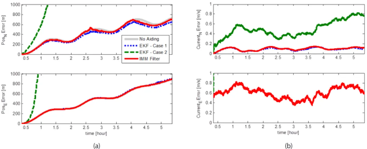
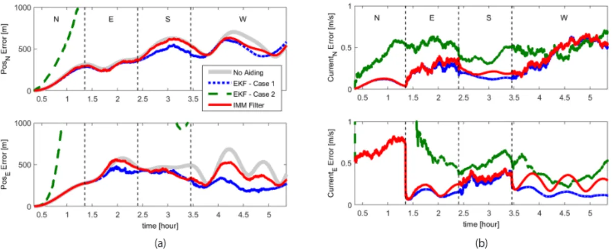
Kim 2008). The IMM subfilters are composed on the basis of multiple models of sea current, and using the residual and residual covariance of each subfilter, various types of sea currents can be properly estimated through the mixing of subfilters. This study verified the performance of the proposed filter by performing Monte-Carlo simulations based on Matlab and analyzing the results.
This paper is organized as follows. Chapter 2 describes the principle and problems of EM-Log and sea current models from previous studies, while Chapter 3 designs the IMM filter-based INS/EM-Log integrated navigation filter.
Chapter 4 verifies the performance of the proposed filter through simulation analysis, and the conclusions are made in the final chapter.
2. EM-LOG AND CURRENT MODEL
This chapter examines the principle and problems of EM-Log used as an auxiliary sensor for the navigation of underwater vehicles, and analyzes the sea current model which needs to be considered based on data from previous
(x )
Bl V V
dt (1) Here,
is the magnitude of the induced electromotive force,
Bis the magnitude of the magnetic flux, B is the intensity of the magnetic field, and
lis the height of the magnetic field cross-section.
In addition, V and
xbV indicate the speed of the sea current flowing in the same direction as the
Cforward direction movement speed of the vehicle, respectively.
If there is no sea current, V can be calculated by dividing the induced electromotive force
xbgenerated from EM-Log by Bl. However, since sea current is always present in actual environment, the information output through EM-Log becomes the log speed or speed through water. Since the speed calculated by INS is the ground speed, a corresponding difference between the EM-Log output speed and sea current occurs, and a correct sea current model is required for the filter design considering this matter.
2.2 Sea Current Model
Sea current consists of sea current and ocean current. Sea current is the flow of seawater created by the gravitational pull of the moon and the sun, and the speed and direction are determined according to time and location. On the other hand, the ocean current is difficult to predict as it is the flow of seawater created by the surface water moved by the frictional force against wind and the deep-sea water moved by the difference of temperature and salinity.
Methods for predicting sea current based on measured information and advance information include ACDIRC, CH3D, and ROMS, but actual implementation is practically difficult. This paper uses the first-order Markov type sea current model proposed by Dmitriev et al. (2012).
1
(1 1 ) 2
C C C C
k C k C k
V t V t w
T T
(2) Here, T is a time constant of the correlation interval of the sea current speed,
C tis the data generation time interval, is the Root Mean Square of the sea current speed, and
Cw
Cis the white noise with standard normal distribution.
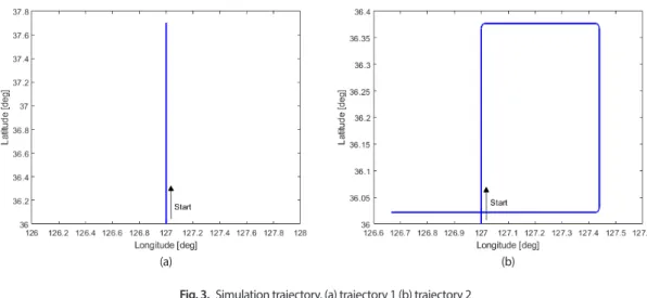
Fig. 1 shows an example of sea current generation. Case 1 is set to T [hr],
C2
C0.5[m/s], while Case 2 is set to
T C 20[hr],
C0.05[m/s]. In other words, Case 1 is the case in which the size and direction of the sea current speed changes frequently due to the influence of the ocean current rather than the sea current in a short period of time, while Case 2 is the case where the change of sea current speed is not large. However, it is practically impossible to set parameter values that accurately predict sea current in a real-world environment that varies depending on the location, time, and weather.
3. IMM-BASED INS/EM-LOG INTEGRATED NAVIGATION FILTER The purpose of this paper is to design an integrated navigation filter that corrects INS error using EM-Log measurements. However, as described above, the error may increase if the sea current included in the EM-Log measurements is not properly compensated. Therefore, a filter should be designed to compensate by adding the sea current to the state variable of the filter. In this
(1)
where, ε is the magnitude of the induced electromotive force, Ф
Bis the magnitude of the magnetic flux, B is the intensity of the magnetic field, and l is the height of the magnetic field cross-section. In addition, V
xband V
cindi- cate the speed of the sea current flowing in the same direction as the forward direction movement speed of the vehicle, respectively.
If there is no sea current, V
xbcan be calculated by dividing the induced electromotive force generated from EM- Log by Bl. However, since sea current is always present in actual environment, the information output through EM-Log becomes the log speed or speed through water.
Since the speed calculated by INS is the ground speed, a corresponding difference between the EM-Log output speed and sea current occurs, and a correct sea current model is required for the filter design considering this matter.
2.2 Sea Current Model
Sea current consists of sea current and ocean current. Sea current is the flow of seawater created by the gravitational pull of the moon and the sun, and the speed and direction are determined according to time and location. On the other hand, the ocean current is difficult to predict as it is the flow of seawater created by the surface water moved by the frictional force against wind and the deep-sea water moved by the difference of temperature and salinity.
Methods for predicting sea current based on measured information and advance information include ACDIRC, CH3D, and ROMS, but actual implementation is practically difficult. This paper uses the first-order Markov type sea current model proposed by Dmitriev et al. (2012).
1 1 1 2
C C C C
k C k C k
V t V t w
T
T
(2)
………..(8)
(1:2)(1)
ˆb (ˆn ˆC)
i n i i EM Log
r C V V %V
(11) 아래는 그림 모양을…
(1) (1) (1)
(1:2) (1:2) (1:3)
ˆ ˆ ( ˆ )
(I ) ( ) ( ) ( )
( )
b n C
n EM Log
b n n n C C b b C
n n EM Log
b n b C b n C n
n n n EM Log
z C V V V
C V V V V V C V w
C V C V C V V w
%
(2)
where, T
cis a time constant of the correlation interval of the
sea current speed, ∆t is the data generation time interval, σ
cSeong Yun Cho et al. IMM-based INS/EM-Leg Integrated Underwater Navigation 167
http://www.ipnt.or.kr is the Root Mean Square of the sea current speed, and w
cis
the white noise with standard normal distribution.
Fig. 1 shows an example of sea current generation. Case 1 is set to T
c=2[hr], σ
c=0.5[m/s], while Case 2 is set to T
c=20[hr], σ
c=0.05[m/s]. In other words, Case 1 is the case in which the size and direction of the sea current speed changes frequently due to the influence of the ocean current rather than the sea current in a short period of time, while Case 2 is the case where the change of sea current speed is not large. However, it is practically impossible to set parameter values that accurately predict sea current in a real-world environment that varies depending on the location, time, and weather.
3. IMM-BASED INS/EM-LOG INTEGRATED NAVIGATION FILTER
The purpose of this paper is to design an integrated navigation filter that corrects INS error using EM-Log measurements. However, as described above, the error may increase if the sea current included in the EM-Log measurements is not properly compensated. Therefore, a filter should be designed to compensate by adding the sea current to the state variable of the filter. In this case, the first-order Markov model shown in (2) can be used for the sea current model, but if the parameters included in this model are not correctly set, the sea current cannot be properly estimated, which makes the results of the integrated navigation worse that the results of the single INS. Considering these problems, this study sets a sea current model with two different parameters, and based on this, uses the IMM filter to configure INS/EM-Log integrated navigation filter as shown in Fig. 2.
3.1 INS time propagation
As shown in Fig. 2, the time propagation of the navi- gation information is performed in two independent INS blocks using the output of IMU and depth gauge.
First, VCD is performed to correct the vertical axis velocity and position using the depth gauge (Seo et al.
2004). Then, the time propagation of the state variable
[
N E]
Tx = L l v v φ θ ψ is performed, which is com- posed of the horizontal axis position, velocity, and attitude (Farrell & Barth 1999). In this state variable, L and l are the latitude and longitude, V
n= [ v
Nv
E]
Tis the north/east direction velocity, and [ φ θ ψ ]
Tis the Euler angle. Then, time prop-agation is performed by using the estimate of sea current V
C= [ v
CNv
C TE] in the north/east direction in the time propagation Eq. (3) derived from Eq. (2).
case, the first-order Markov model shown in (2) can be used for the sea current model, but if the parameters included in this model are not correctly set, the sea current cannot be properly estimated, which makes the results of the integrated navigation worse that the results of the single INS. Considering these problems, this study sets a sea current model with two different parameters, and based on this, uses the IMM filter to configure INS/EM-Log integrated navigation filter as shown in Fig. 2.
3.1 INS time propagation
As shown in Fig. 2, the time propagation of the navigation information is performed in two independent INS blocks using the output of IMU and depth gauge. First, VCD is performed to correct the vertical axis velocity and position using the depth gauge (Seo et al. 2004). Then, the time propagation of the state variable x [ L l v
Nv
E ]
Tis performed, which is composed of the horizontal axis position, velocity, and attitude (Farrell & Barth 1999). In this state variable, L and
lare the latitude and longitude, V
n [ v
Nv
E]
Tis the north/east direction velocity, and [ ]
Tis the Euler angle. Then, time propagation is performed by using the estimate of sea current V
C [ v
CNv
C TE] in the north/east direction in the time propagation Eq. (3) derived from Eq. (2).
, 1 1 ,
ˆCj k (1 C )ˆCj k, { , }
i
v t v j N E
T
(3) Here,
i {1,2}refers to the number of the model configured with different parameters, and the two time-constants are set through simulation.
3.2 INS/EM-Log Measurement Update
If the EM-Log measurements are acquired periodically, update the measurements according to this cycle. First, set the error state variable for updating the measurements based on the Extended Kalman Filter (EKF) as shown in Eq. (4).
[
N E N E D x y z x y z CN EC T]
x L l v v v v
(4)
Here,
n [
N
E
D]
Tis the attitude error expressed in the navigation coordinate system, and [
x
y
z]
Tand [
x
y
z]
Tare the accelerometer bias and gyro bias, respectively.
The Jacobian matrix is configured as shown in Eq. (5).
( ) F t k
k
e
(5) Here,
kis the measurement update cycle, and ( ) F t is shown in Eq. (6).
13 13 2
2 13
( ) 0
( ) 0
INS EM LogF t F t F
(6) (3)
where, i ∈ {1,2} refers to the number of the model config- ured with different parameters, and the two time-constants are set through simulation.
3.2 INS/EM-Log Measurement Update
If the EM-Log measurements are acquired periodically, update the measurements according to this cycle. First, set the error state variable for updating the measurements based on the Extended Kalman Filter (EKF) as shown in Eq. (4).
case, the first-order Markov model shown in (2) can be used for the sea current model, but if the parameters included in this model are not correctly set, the sea current cannot be properly estimated, which makes the results of the integrated navigation worse that the results of the single INS. Considering these problems, this study sets a sea current model with two different parameters, and based on this, uses the IMM filter to configure INS/EM-Log integrated navigation filter as shown in Fig. 2.
3.1 INS time propagation
As shown in Fig. 2, the time propagation of the navigation information is performed in two independent INS blocks using the output of IMU and depth gauge. First, VCD is performed to correct the vertical axis velocity and position using the depth gauge (Seo et al. 2004). Then, the time propagation of the state variable x[L l vN vE ]T is performed, which is composed of the horizontal axis position, velocity, and attitude (Farrell & Barth 1999). In this state variable, L and l are the latitude and longitude, Vn[vN vE]T is the north/east direction velocity, and [ ]T is the Euler angle. Then, time propagation is performed by using the estimate of sea current VC[vCN vC TE] in the north/east direction in the time propagation Eq. (3) derived from Eq. (2).
, 1 1 ,
ˆCj k (1 C )ˆCj k, { , }
i
v t v j N E
T (3) Here, {1,2}i refers to the number of the model configured with different parameters, and the two time-constants are set through simulation.
3.2 INS/EM-Log Measurement Update
If the EM-Log measurements are acquired periodically, update the measurements according to this cycle. First, set the error state variable for updating the measurements based on the Extended Kalman Filter (EKF) as shown in Eq. (4).
[ N E N E D x y z x y z CN C TE]
x L l v v v v
(4)
Here, n[N E D]T is the attitude error expressed in the navigation coordinate system, and [x y z]Tand [x y z]T are the accelerometer bias and gyro bias, respectively.
The Jacobian matrix is configured as shown in Eq. (5).
( ) F t k
k e
(5) Here, k is the measurement update cycle, and ( )F t is shown in Eq. (6).
13 13 2
2 13
( ) 0
( ) 0INS EM Log
F t F t F
(6)
![Fig. 1 shows an example of sea current generation. Case 1 is set to T c =2[hr], σ c =0.5[m/s], while Case 2 is set to T c =20[hr], σ c =0.05[m/s]](https://thumb-ap.123doks.com/thumbv2/123dokinfo/5263119.632100/3.909.495.790.130.356/fig-shows-example-sea-current-generation-case-case.webp)