https://doi.org/10.5050/KSNVE.2018.28.5.567 ISSN 1598-2785(Print), ISSN 2287-5476(Online)
1)
1. 서 론
현대 산업의 고도화로 연구, 개발 및 생산, 검사 공정 등 다양한 분야에서 정밀장비의 사용이 필수적 으로 요구되고 있다. 또한 최근에 반도체 핵심 기술 이 소형화, 고용량화, 고집적화 됨에 따라 대다수의 반도체 및 디스플레이 장비에서의 고정밀도 및 신뢰 성 확보가 시급한 사항이다(1~3). 생산 공정에서의 정밀도 허용범위가 마이크로미터에서 나노미터 급 으로 정밀해지고 있는 현재, 지반진동은 안정적인
동작과 기능을 저해하는 급격한 문제점으로 나타나 고 있다(4). 지반진동은 지진, 설비, 인근 차량 혹은 사람의 유동 등 많은 복합적인 요소들을 변수로 갖 는다. 이를 해석하는 방법은 응답스펙트럼해석법(5,6) 과 시간이력해석법(7) 등이 있으며 응답스펙트럼해 석법은 비교적 계산이 용이하고 간편하지만 시간 에 따른 구조물의 응답을 구할 수 없다. 이에 비 해 시간이력해석법은 운동방정식을 연속적으로 시 간 증분마다 단계적으로 수치적분을 함으로서 시 간에 따른 구조물의 응답을 해석할 수 있는 방법 이지만 시간이 많이 소요되고 막대한 계산량이 요
† Corresponding Author ; Member, Dept. of Mechanical System Engineering, Kyonggi University
E-mail : [email protected]
* Dept. of Mechnical System Engineering, Kyonggi University
‡ Recommended by Editor Gi-Woo Kim
ⓒ The Korean Society for Noise and Vibration Engineering
전달행렬법을 이용하여 지반진동을 받는 전단구조물의 응답해석
Response Analysis of Shear Structure Subjected to Ground Vibration Using the Transfer Matrix Method
조 찬 우*· 이 준 성**· 이 정 윤†
Chan U Jo
*, Joon-Seong Lee
**and Jung Youn Lee
†(Received July 13, 2018 ; Revised August 21, 2018 ; Accepted August 21, 2018)
Key Words : Expanded Transfer Matrix Method(확장된 전달행렬법), Vibration Analysis(진동해석), Transfer Function (전달함수), Ground Vibration(지반진동)
ABSTRACT
Shear story structures are widely used in industrial equipment structure and building design but are of- ten vibrated during the vibration of the ground. Ground vibration is caused by many variables such as earthquake, mechanical vibration, vehicle and human steps. As a result, a study on the vibrational response of this type of structure is important to both accuracy product and future building designs. Traditionally, fi- nite element methods such as the ANSYS and MIDAS have been used as the primary methods of comput- ing the response of such a structure. However, these methods yield low calculation efficiencies. In this pa- per, the mechanical model of a four-story shear structures is constructed based on the expanded transfer matrix method. The expanded transfer matrix of the components in the model and the total transfer matrix equation of the structure are derived, and the corresponding MATLAB program is compiled to determine the natural frequencies and response of the structure. The results of the transfer matrix are in good agree- ment with the results of the modal analysis.
구되는 단점이 있다. 따라서 간단하게 시간에 따 른 구조물의 정상상태의 응답을 구하는 방법이 필 요하게 되었다.
이를 위해 전단구조물의 지반응답을 전달행렬법(8,9) 을 사용하여 확장된 전달행렬을 만들었으며 기존 의 방법에 비해 비교적 손쉽게 해석하는 방법을 개발하였다. 먼저 지반진동의 입력신호를 작성하 기 위해 반도체 장비가 설치 예정인 장소의 지반 진동에 대한 가속도 신호를 측정하였다. 이 신호 를 필터링을 통해 노이즈를 제거하고 변위신호로 변환하였다. 지반과 각 층의 질점과의 전달함수를 확장된 전달행렬로 해석하는 방법을 새롭게 개발 하여 지반진동이 각 층의 변위에 미치는 영향을 검토하였다.
2. 이 론
2.1 전단구조물의 전달행렬법
전달행렬법의 전달행렬을 구하기 위하여 Fig. 1과 같이 나타내었다. Fig. 1에서 번째 요소의 횡 방향 전달행렬은 아래 식과 같다.
(1)여기서 는 각각 횡 변위와 전단력을 나타내는 상태벡터이며 는 요소의 위쪽과 아래쪽을 나타 내고 는 전단구조물 기둥의 횡 방향의 스프링 상 수를 의미한다.
번째 질량 에 대한 위쪽과 아래쪽의 점 전달 행렬은 아래와 위 변위가 동일하지만 관성력이 있으
므로 다음과 같이 나타낼 수 있다.
(2)여기서 스프링과 질량에 대한 행렬을 동시에 고려하 면 다음과 같이 표현된다.
(3)
따라서 번째 요소의 전달행렬 은 다음과 같이 나타낼 수 있다.
(4)
Fig. 1에서 번째 질량 에 의 주기적인 외부 힘이 작용할 때 관성력을 평형을 고려하면 다음과 같이 나타낼 수 있다(9).
(5)
외부 힘을 고려하여 단일 항으로 나타내면 다음 식과 같이 표현되어진다.
⋯
⋮
⋮
⋯⋯⋯ ⋯⋯⋯ ⋯⋯⋯ ⋯⋯⋯
⋮
⋯
(6)
따라서 번째 요소의 확장된 전달행렬
은 다음과 같이 나타낼 수 있다.
⋮
⋮
⋯⋯⋯ ⋯⋯⋯ ⋯⋯⋯ ⋯⋯⋯
⋮
(7) Fig. 1 Transfer matrix schematic diagram and
free-body diagram of mass
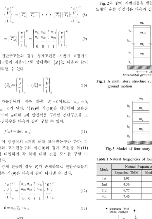
이때의 상태벡터는 다음 식과 같다.
⋯
∙∙∙
⋯
(8)
⋯
⋮
⋮
⋯ ⋯ ⋯ ⋯
⋮
⋯
(9)
전단구조물의 경우 경계조건은 지반이 고정이고 최고층이 자유이므로 상태벡터
는 다음과 같이 나타낼 수 있다.
⋯
⋯
(10)
자유진동의 경우 하중 이므로 ,
가 된다. 식 (9)에 식 (10)을 대입하여 고유진 동수에 대한 n차 방정식을 구하면 전단구조물 고 유진동수를 다음과 같이 구할 수 있다.
det
(11)이 방정식의 개의 해를 고유진동수라 한다. 각 차의 고유진동수와 식 (10)의 경계 조건을 식 (11) 에 대입하면 각 차에 대한 진동 모드를 구할 수 있다.
강제 진동의 경우 가 존재하므로 전단구조물의 경우 식 (9)은 다음과 같이 나타낼 수 있다.
⋯
⋮
⋮
⋯ ⋯ ⋯ ⋯
⋮
⋯
(12)
(13)
(14)
식 (10)에 있는 지반의 상태 벡터를 식 (7)에 대입 하면 강제진동이 있을 때 각 지점의 상태벡터를 구 할 수 있다. 이를 이용하면 측정 점 와 가진 점 의 전달함수 를 해석할 수 있다.
2.2 지반진동 이론
Fig. 2와 같이 지반진동을 받는 비 감쇠계 다자유 도계의 운동 방정식은 다음과 같다.
Fig. 2 A multi story structure subjected to horizontal ground motion
Mode Natural frequency(Hz)
Remark Expanded TMM Modal analysis
1st 1.93 1.93
2nd 4.56 4.56
3rd 6.77 6.77
4th 7.46 7.46
(a) 1st (b) 2nd (c) 3rd (d) 4th Fig. 4 Mode shapes of the four story shear structure Table 1 Natural frequencies of four story shear building
Fig. 3 Model of four story shear structure
∙∙
(15)여기서 은 질량행렬, 는 강성행렬, 은 지 반과 질량 을 연결하는 스프링이고 는 지반 진동의 변위이다.
2.3 주파수영역 해석법을 이용한 응답해석 구조물에 가진되는 가진력 는 다음 식과 같 이 나타낼 수 있다.
∞
∞
(16)
∞∞ (17)식 (16)은 주파수함수 의 역 푸리에 변환 (inverse Fourier transform)이며 식 (17)은 시간함수 인 의 푸리에 변환을 나타낸다.
가진력 에 대한 선형시스템의 응답은 식 (16) 의 각각의 조화 가진에 대한 응답을 조합함으로써 얻어질 수 있으며 다음과 같이 나타낼 수 있다.
∞
∞
(18)
(19)
여기서 는 시스템의 전달함수이다.
3. 적용 예
전달행렬법을 이용하고 지반진동을 받는 전단구 조물의 응답해석을 검증하기 위하여 Fig. 3과 같이 4층 전단구조물에 대한 고유치 해석을 수행하였다.
수치해석 대상 모델은 제원은 다음과 같다. 질량은 m1이 4500 kg, m2와 m3는 3000 kg, m4는 500 kg이 다. 스프링 탄성상수는 k1이 3200 kN/m이고 k2는 2400 kN/m, k3는 1600 kN/m, k4는 800 kN/m이다.
4. 결과 및 고찰
4.1 고유진동수와 고유모드
제안된 지반 진동에 확장된 전달행렬법과 모드해
석(modal analysis)을 사용하여 Fig. 3에 나타낸 4층 전단구조물의 고유진동수와 고유모드를 구해 각각 Table 1과 Fig. 4에 나타내었다. 4자유도 계이므로 모두 4개의 고유진동수와 고유모드가 구해졌으며 두 방법이 일치하므로 제안된 방법이 타당함을 알 수 있었다.
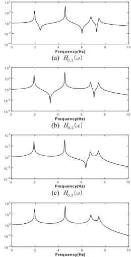
4.2 전달함수
지반 진동에 의한 각 층의 진동을 해석하기 위해 서는 지반과 각 층 사이의 전달함수가 필요하게 된 다. 지반 변위함수가 이고 지반과 질량 사 이의 스프링상수를 으로 하면 지반 진동에 의해 발생되는 힘은 가 된다. 이를 식 (7)과 식 (14)을 이용하여 전달 함수를 구하였으며 Fig. 5 에 나타내었다. 지반에 대한 총 4개 층에 대한 전달
2
0 4 6 8 10
F req u e n cy(Hz) 10-4
10-2 100 102 104
(a)
0 2 4 6 8 10
Frequency(Hz) 10-4
10-2 100 102 104
(b)
0 2 4 6 8 10
Frequency(Hz) 10-4
10-2 100 102 104
(c)
0 2 4 6 8 10
Frequency(Hz) 10-4
10-2 100 102 104
(d)
Fig. 5 Transfer function of the four stories shear structure
함수를 나타내었으며 는 가진 점와 측정 점
의 전달함수를 의미한다.
4.3 주기함수에 대한 응답 비교
지반에 Fig. 6과 같이 주기함수인 변위 신호를 주 고 각 층의 변위응답을 식 (18)을 사용하여 구하였 으며 Fig. 7에 나타내었다. 층이 올라갈수록 변위가
많이 발생되었다. 실선은 전달행렬법의 전달함수를 사용하여 예측한 결과이고 점선은 모드 해석(modal analysis)을 사용하여 얻는 결과이다. 두 방법이 잘 일치하였다.
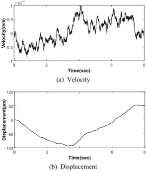
4.4 지반 가속도의 변위 변환
지반진동으로 인한 구조물의 변위응답을 구하기 위해 측정된 지반 가속도를 Fig. 8에 나타내었다.
이 지반진동의 가속도를 시간에 따라 적분하여 속 도로 Fig. 9(a)에 나타내었으며 이를 다시 적분하여 변위신호로 변환하여 Fig. 9(b)에 나타내었다. 지반진 동 특성상 지반의 변위는 어느 기준 위치에서 진동한 다고 볼 수 있으므로 시간에 따른 변위신호의 평균 추세선 값이 수평이 되어야 한다. 하지만 Fig. 9(b)의
0 2 4 6 8
Time(sec) -30
-15 0 15 30
Displacement(μm) x(t)=sin(2π*0.25t)+3sin(2π*3t)+5sin(2π*8t)
0 0 30
00 2 6 8
Time(sec) -30
-15 0 15 30
Displacement(µm) x(t)=sin(2p *0.25t)+3sin(2p *3t)+5sin(2p *8t)
Fig. 6 The displacement time curve for the ground vibration with a period function
1
0 2 3 4 5 6 7 8
Time(sec) -30
0 30
(a) Ground
00 2 6 8
-30 0 30
(b) 1st floor
00 2 6 8
-30 0 30
(c) 2nd floor
2
00 6 8
-30 0 30
(d) 3rd floor
2
00 6 8
-30 0 30
(e) 4th floor
Fig. 7 Calculated each floor displacement by the ground vibration with a period function
-
Displacement(µm)
0 2
0 6 8
Time(sec) -6
-3 0 3 6
Acceleration(m/s2) 10-3
Fig. 8 Ground acceleration signal from the experiment
00 2 6 8
Time(sec) -1
-0.5 0 0.5 1
Velocity(m/s)
10-4
(a) Velocity
00 2 6 8
Time(sec) -120
-60 0 60 120
Displacement(µm)
(b) Displacement
Fig. 9 Velocity and displacement obtained by in- tegrating acceleration
변위신호는 추세선이 수평과 일치하지 않기 때문에 속도에 대해 푸리에 변환하여 Fig. 10에 나타내었으 며 검토한 결과 0.5 Hz 이하 성분이 상당히 높게 나 타났다. 이는 가속도계 특성상 저주파는 측정하기 어 려워 노이즈를 측정할 가능성이 높기 때문이다.
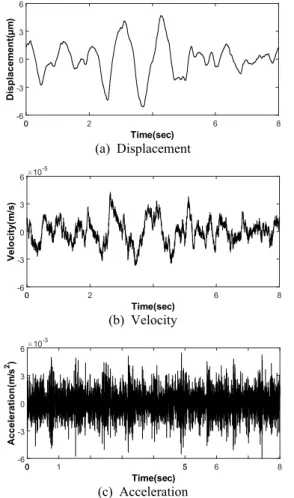
하이패스필터를 사용하여 변위의 추세선이 수평 이 되도록 문제되는 0.5 Hz 이하의 저주파 성분을 제거한 다음 역 프리에 변환을 하여 Fig. 11에 나타 내었다. Fig. 11에 있는 가속도, 속도, 변위의 추세 선을 보면 수평과 잘 일치함을 알 수 있다. 또한 Fig. 8의 실험한 가속도와 필터링한 가속도 신호가 거의 같음을 알 수 있다. 따라서 지반진동의 변위는 Fig. 11(a)를 사용하여 전단구조물의 응답해석을 하 였다.
4.5 지반 진동에 의한 응답 비교
Fig. 11(a)에 있는 지반 변위함수를 입력으로 전 단 구조물에 적용한 결과 각 층의 변위응답은 Fig.
12와 같이 나타났다. 실선은 전달행렬법의 전달함 수를 사용하여 예측한 결과이고 점선은 모드 해석 (modal analysis)을 사용하여 얻는 결과이다. 두 방 법이 잘 일치하여 제안한 방법이 타당함을 알 수 있었다.
0 2 4 6 8 10
Frequency(Hz) 0
2.5 5
Velocity(m/s)
10-5
0 0 30 2
0 4 6 8 10
Frequency(Hz) 0
2.5 5
Velocity(m/s)
10-5
Fig. 10 The FFT of the velocity obtained by in- tegrating experimental acceleration
2
00 6 8
Time(sec) -6
-3 0 3 6
Displacement(µm)
(a) Displacement
2
00 6 8
Time(sec) -6
-3 0 3 6
Velocity(m/s)
10-5
(b) Velocity
0000 1 55 6 8
Time(sec) -6
-3 0 3 6
Acceleration(m/s2) 10-3
(c) Acceleration
Fig. 11 Displacement, velocity and acceleration with the high-pass filter
2
0 4 6 8
Time(sec) -30
0 30
(a) Ground
-30 0 30
(b) 1st floor
-30 0 30
(c) 2nd floor
-30 0 30
(d) 3rd floor
-30 0 30
(e) 4th floor
Fig. 12 Calculated each floor displacement by the ground vibration with experiment
-
Displacement(µm)
5. 결 론
지반진동이 있을 때 전단구조물의 응답해석을 전 달행렬법을 이용하여 해석하였으며 다음과 같은 결 론을 얻었다.
(1) 확장된 전달행렬법을 사용하여 전단구조물의 전달함수를 해석하는 방안을 개발하였다.
(2) 지반진동이 있을 때 전달함수와 푸리에 변환 과 역 변환을 이용하여 전단 구조물의 응답을 해석 하는 방안을 제시하였다.
(3) 측정된 지반 가속도 신호의 노이즈를 제거하 여 지반 변위 신호로 변한하는 방법을 제시하였다.
(4) 지반 진동에 의한 전단 구조물의 응답을 제안 한 방법과 모드해석으로 해석한 방법으로 비교한 결 과 서로 잘 일치하여 제안한 방법의 타당성을 검증 하였다.
후 기
이 연구는 2017학년도 경기대학교 대학원 연구 장학생 장학금 지원에 의해 수행되었음.
References
(1) Normura, K., Kamiya, T. and Hosono, H., 2011, Ambipolar Oxide Thin-film Transistor, Advanced Materials, Vol. 23, pp. 3431~3434.
(2) Park, C., 2017, A Study on Technology Diffusion Trend Considering Technological Performance Enhancement and Economics: Case of Technology Evolution of 32 nm, 22 nm, 14 nm Logic Semiconductors, Journal of the Korea Academia-Industrial Cooperation Society, Vol. 18, No. 2, pp.
177~184.
(3) Lewyn, L. L., Ytterdal, A. C. and Martin, K., 2009, Analog Circuit Design in Nonoscale CMOS Technologies, Vol. 97, No. 10, pp. 1687~1714.
(4) Robert, M. S., 2012, Ultra-precision Engineering in Lithographic Exposure Equipment for the Semiconductor Industry, Philosophical Transactions of the Royal Society, Vol. 370, pp. 3950~3972.
(5) Patil, S. S., Ghadge, S. A., Konapure, C. G. and Ghadge, C. A., 2014, Seismic Analysis of High-Rise
Building by Response Spectrum Method, International Journal of Computational Engineering Research, Vol. 3, No. 3, pp. 272~279.
(6) Ky, L., Chatpan, C. and Toshiro, H., 2014, Seismic Shear Forces in Shear Walls of a Medium-rise Building Designed By Response Spectrum Analysis, Engineering Journal, Vol. 18, No. 4, pp. 73~95.
(7) Hosseini, M., Hosseini, B. and Safi, Z., 2017, Seismic Design Evaluation of Reinforced Concrete Buildings for Near-source Earthquakes by Using Nonlinear Time History Analyses, Procedia Engineering, Vol. 199, pp. 176~181.
(8) Kim, J. H., Kwak, J. H., Lee, J. W. and Lee, J.
Y., 2016, Dynamic Analysis of Cracked Timoshenko Beams Using the Transfer Matrix Method, Transactions of the Korean Society for Noise and Vibration Engineering, Vol. 26, No. 2, 179~186.
(9) Lee, J. W. and Lee, J. Y., 2016, Free Vibration Analysis Using the Transfer-matrix Method on a Tapered Beam, Computers and Structures, Vol. 164, pp.
75~82.
Chan U Jo received a B.E in me- chanical engineering in 2016 from Kyonggi University in Suwon, Republic of Korea. He is currently an MS candidate graduate at the department of mechanical engineer- ing, Kyongggi University. His re- search interests are in Structural Response by Ground Vibration and Modal Analysis of Vibration.
Jung Youn Lee is Professor of Dept. of Mechanical System Engineering at Kyonggi University, where he has been since 1996. He received a B.S., an M.S. and his Ph.D. from Hanyang University in 1979, 1989 and 1992 respectively.
His research interests are in System Identification, Structural Modification, Inverse Problem, Modal Analysis and Sensitivity Analysis of Vibration.