1. INTRODUCTION
The autonomous driving method using magnetic sensors recognizes the position by measuring magnetic fields in autonomous robots or vehicles after installing magnetic markers in a moving path. The Position estimate method using magnetic sensors has an advantage of being affected less by variation of driving environment such as oil, water and dust due to the use of magnetic field [1].
It also has the advantage that we can use the magnet as an indicator and there is no consideration for power and communication environment [1, 2]. With such a reason, non-contact position recognition technology using magnetic field has been applied in various areas because a magnet, which is the object for measurement, has an excellent economy from autonomous driving to precision equipment like wafer device. However, the method has a
problem with the high cost because it has to use AMR sensors and other expensive components [3, 4].
When we need to cover sufficient distance with magnet like an autonomous driving, and requiring precise measurement, we have to consider external noise. There are also methods such as geometric mapping which are inefficient due to nonlinearity between the measured value and real position. It is also difficult to control and to compute exact external noise values continuously because we only know the differential value of both sensors as a value of geomagnetism elimination.
Ryoo and Kim [3-9] estimated the position of a magnet by using the geometrical method after which they get maximum value of perpendicular components and values of surrounding sensors. However, these methods have disadvantages that complicate the algorithm and lead to errors according to area.
In this paper, we propose an efficient sensor system for an autonomous driving vehicle supplemented for existing disadvantage. In order to efficiently eliminate geomag- netism, we analyze the components of the horizontal and vertical magnetic field. We propose an algorithm for position estimation to ease analysis, and also propose an initialization method for sensors applied in the vehicle. We measured and analyzed the developed system in various environments, and we verify the advantages of proposed methods.
1Korea Institute of Science and Technology Information, Daejeon, 305- 806, Korea
2School of Internet and Info. Comm., Shingyeong Unversity, Kyonggi, 445-741, Korea
3School of Electrical Engineering, Chonnam Unversity, Gwangju, 500- 757, Korea
+Corresponding author: [email protected]
(Received : Jan. 30, 2013 , Revised: Mar. 19, 2013, Accepted : Mar. 20, 2013) This is an Open Access article distributed under the terms of the Creative Commons Attribution Non-Commercial License(http://creativecommons.org/licenses/by- nc/3.0)which permits unrestricted non-commercial use, distribution, and reproduction in any medium, provided the original work is properly cited.
http://dx.doi.org/10.5369/JSST.2013.22.2.111 pISSN 1225-5475/eISSN 2093-7563
Position Recognition System for Autonomous Vehicle Using the Symmetric Magnetic Field
Eun-Ju Kim1,+, Eui-Sun Kim2, and Young-Cheol Lim3
Abstract
The autonomous driving method using magnetic sensors recognizes the position by measuring magnetic fields in autonomous robots or vehicles after installing magnetic markers in a moving path. The Position estimate method using magnetic sensors has an advantage of being affected less by variation of driving environment such as oil, water and dust due to the use of magnetic field. It also has the advantages that we can use the magnet as an indicator and there is no consideration for power and communication environment. In this paper, we propose an efficient sensor system for an autonomous driving vehicle supplemented for existing disadvantage. In order to efficiently eliminate geomagnetism, we analyze the components of the horizontal and vertical magnetic field. We propose an algorithm for position estimation and geomagnetic elimination to ease analysis, and also propose an initialization method for sensor applied in the vehicle. We measured and analyzed the developed system in various environments, and we verify the advantages of proposed methods.
Keywords : Autonomous vehicles, Position sensor, Hall sensor, Magnetic marker, Symmetric magnetic field
2. METHODS
2.1 Position recognition of magnetIn order to form the magnetic field, we have to install permanent magnet in the path of the tracking system or autonomous driving system to use the magnetic field sensor. The permanent magnet is laminated by several sheets in order to achieve a magnetic field with the desired size. The value of a magnetic field measured in sensor may be different under various conditions [2].
To recognize the position of the magnet we can get the precise value of position as calculating a difference value of sensors located on both sides of a magnet, and typically the perpendicular magnetic field has been used a lot.
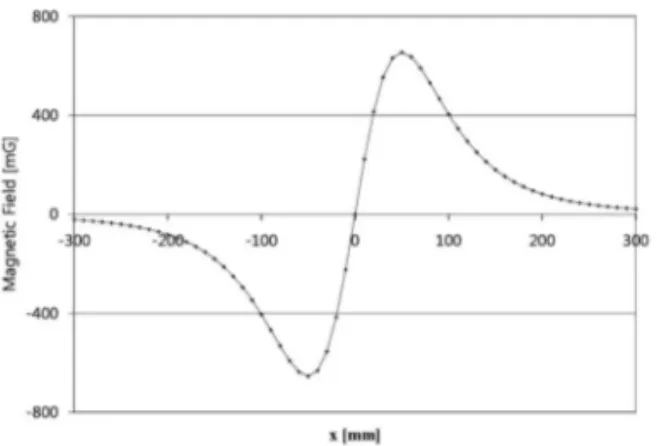
In this paper, in order to estimate the position of magnet we make use of the method that can estimate the position with small amount of calculation by using the horizontal magnetic field . The magnetic field in three-axis can be represented like an equation (1), we know it has an inverse proportion to 5 powers of the distance.
Fig. 1 shows magnetic field for variation of x value after the value fix as y= 0, z=10. Fig. 1 has a mean that horizontal magnetic field forms a point symmetry and has a linearity within approach distance. Thus we can know the precise position of the magnet using a simple proportional expression pass through x= 0 point [1].
2.2 Geomagnetic elimination
The value of the magnetic field measured by a magnetic sensor also contains a level of noise due to geomagnetism.
The value of geomagnetism in Korea is about 500 mG, indicating magnitude between 200-300 mG per each axis.
Because it is such a large noise compared with the position recognition values within the range of several hundred [mG], we have to eliminate it.
This method can eliminate the effect of geomagnetism and its disturbance using summation and difference of values of two sensors. However this method cannot estimate the position of the magnetic marker directly because it may find summation and difference of value between the two sensors. Therefore we estimate the position of a magnetic marker by using complicated algorithms.
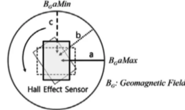
In this paper we propose to eliminate external disturbance using the maximum and minimum of measured value as a method to eliminate geomagnetism in real-time. The curve shape of the horizontal magnetic field component from the magnet make a point symmetric type due to symmetry of the magnetic field; the value of geomagnetism in one direction could be affected by both sensors as centered magnet by opposite direction of each other.
As a result, the graph measured for the horizontal component happen shifting in the direction of vertical axis only. We calculate the measurement value using such symmetry. We know that the value by disturbance like equation (2) is the difference between measurement value and intermediate value, which is center between maximum and minimum.
Fig. 1. Distribution of horizontal component of magnetic field of magnet.
Fig. 2. Geomagnetism elimination using max-min value.
B = (3xzax+3yzay+(2z2 - x2 - y2)az )[ G ] 4πr5
M
M = magnetic moment , r = x2+y2+z2
(1)
Where B
maxmeans maximum value of magnetic field, B
minis the minimum value of magnets, B
gis geomagnetism and B
vrepresents the effects of vehicle and environment.
From equation (2) if we assume –B
+mB
–mwe can get equation (3).
Thus we can find the exact value P
0as in Fig. 2, which is magnet position to eliminate external disturbance. If more complicate calculation arrows of us, more exact analysis of geomagnetism is possible by various methods through segment analysis of curve of point symmetry.
2.3 Offset's elimination of hall sensor
In order to measure the offset value of a hall sensor precisely, we need to use a standard device measuring magnetic field which can compensate geomagnetism by real time. However, in cases of a common precision environment such as an AD environment, we can assume that geomagnetism is constant for the earth pole and we can get the offset value. Generally, in the case of sensors to measure the magnetic field of a single axis only, we measure the value from the sensor to the decided position first, then we add this value and the measured value when the sensor direction rotates 180 degrees at the same position. This eliminated values measured in the oppose direction to each other, only twice the value remains for sensor offset.
In this paper we consider two view points. One point is that the sensor module could be applied to autonomous driving vehicle which is able to steer. Another point is sensor contamination. We propose the simple method without necessary exact measurement. We use in here, one directional sensor. If the sensor and Geomagnetism direction became 90 degrees, measured value is zero; only noise value will be left. In order to achieve this method, we propose the method that taking offset value with orthogonal position between sensor and geomagnetism.
Here we measure the data from the sensor module rotating more than 90 degrees from a reference point in the sensor as shown in Fig. 3.
3. EXPERIMENTAL RESULT
3.1 Experimental results of sensor systemAfter we perform D/A conversion for receiving data as an input from a hall sensor, we estimate the position of a magnet using the position recognition algorithm. The estimated position values of the magnet display a voltage value converted using the D/A converter, and its value transmits to the LCD and computer through RS-232 communications. We used an ATmega2560 in order to process A/D conversion and for data processing of sensor values.
A used hall sensor is HAL81 by made in MICRONAS Company; measurement range is ±30-150 mT. It is designed to program for measurement range of magnetic field, maximum and minimum voltage, and sensitivity etc.
The hall sensor HAL81 made by MICRONAS Company;
measurement range is ±30-150 mT. It is programmed for measurement range of magnetic field, maximum and minimum voltage, and sensitivity.
This hall sensor arranges 32 units with 1cm intervals like Fig. 4. Those are kept at same interval with each other and then we fixed another plate to identically to the other plate in location.
We find the maximum and minimum values among measured values of 32 unit hall sensors and then we
Fig. 3. Offset elimination of the hall sensor by using rotation.
Fig. 4. Sensor system.
B max = B+m+Bg+Bv (2) B min = B-m+Bg+Bv
B max +B min = 2(Bg+Bv) (3)
eliminated the value that is influenced by an external magnetic field such as geomagnetism. We calculated exact positions of the magnet located among sensors using the values of two adjacent sensors passing through the point of y=0.
An existing sensor system was incongruent for the mobile sensor system because it is designed to repeatedly disturb the value that was obtained in the process of initialization as fixed type. Because the AD sensor system proposed in this paper has an object applying to the vehicle that has a frequent directional switch, this system has been designed to reflect and measure value of magnetic field for disturbance by real time.
We measure and convert sensor voltage arranged with 32 chips and then compare the converted values. After calculating the sensor values of left and right passing zero point and magnetic field values due to external influence, we calculate the position of the magnet located between both sensors.
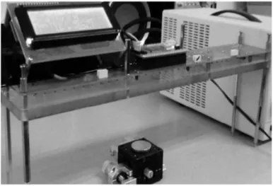
We performed experiments of position recognition using a developed sensor system. We placed the sensor at a fixed height as shown in Fig. 6. We fixed a micro plate on the experimental table, and included a built-in magnet on the micro plate in order to remain fixed.
A microplate used in the experiment shown in Fig. 7 can be moved a minimum of 0.001 cm when it moves once, and it can be moved to orthogonal 2 axis directions on the plane. We processed an experiment when we fixed a magnet on the upper center, moving a constant distance.
The sensor system had attached 32 chip hall sensors, however we only used values of two sensors to estimate position finally. The position estimate process applied between two adjacent sensors repeated identically in another section. Thus we performed measurements for 1 cm sections between two adjacent sensors of arbitrary position.
We display results of measurement to LCD (Fig. 6) after we measured section with 0.01 cm spaces. Fig. 8 represents the result of measurement as a graph at 8 cm heights. It indicates reference value, real estimate value and the errors between them. We get 0.015 cm as a maximum error, which is less than the level of 0.01963 cm when we have a 2% noise error which means maximum error.
Fig. 5. Algorithm of position recognition. Fig. 7. Microplate.
Fig. 6. Measurement device for position recognition of magnet.
Fig. 9 shows errors when we measure at several heights.
We switched between values 3, 5, 8, 10 cm as heights and measured in two cases with 0, 5 cm on the y-axis direction.
The force of the magnet in each case is sufficiently large that the hall sensor does not saturate.
We know that the error increases more while height is lower. It is the same result as the predicted result when we analyze theoretically. However, if height raises by more than 5 cm, there is no tendency for error size. We recognize error size is less than 0.02 cm, a similar level compared to when we measure within 5 cm. This is a similar level when the maximum error of 2% noise level is 0.01963 cm.
3.1 Application of autonomous driving vehicle
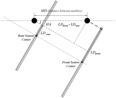
In this paper we did not perform real motion tests for an AD vehicle. However, in order to show practical use as a sensor for position recognition, we performed an experiment in an identical environment as a path for an AD vehicle. In this paper we discuss a two wheel robot type vehicle. Fig. 10 shows two variables that can classify the position of a vehicle in an AD path. We define the
deviation degree, the angle that the vehicle deviates from the center of the path, as a lateral deviation (LD). It defines the distance between the center of the path and the vehicle’s center. Here the vehicle center is used as a center point between two wheels.
We also define the heading angle (HA) as the degree deviated from the forward direction in the vehicle path direction. We find the difference between path direction and vehicle direction.
In Fig. 10, the small circle at the path is made to form the necessary magnetic field by stacking several permanent magnets as the magnetic marker. We have to control the vehicle so that the two variables LD and HD become zero.
However, we cannot get the value of HA with only one sensor. However, we cannot get the value of HA with only one sensor. Thus we use one more sensor in order to compute the value of HA as in Fig. 10.
Fig. 9. Errors for several cases.
Fig. 10. Arrangement of sensor module.
Fig.11. Calculation of geometrical HA.
Fig. 8. Position recognition and error.
After we arranged two sensing units with the magnetic marker spacing in front and rear of the vehicle, we get LD of front and rear sensor. We can find HA using the geometrical equations. To get LD and HA, we can draw with simplification from Fig. 10, and it becomes Fig. 11.
Using Fig. 11, we can yield equation (4) following as:
Fig. 12 represents the experimental method used. After arranging two sensor systems on the identical plane with the interval of the magnet in parallel, we measure the position of the magnet with each other at constant height.
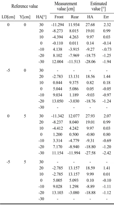
We yield HA by applying the values measured into the equation (4). We measured with providing change at LD, HA and longitudinal direction. Then we compare the real value with the computed value. We measured LD and longitudinal direction for four cases as a combination of 0 cm and 5 cm. We measured from –30° to 30° changing with 10° increments. We represent of measurement method in Fig. 13 and also displays the result of measurement in
Table 1. From Table 1 we can recognize that there are no data in ±30° for either case. It means that we cannot get data because it is in the too far range of the sensor.
In table 1, we represent measured values located in front and rear of the sensor; we also represent HA values calculated after applying measured value into equation (4) and error value. Typically, we know that there is a correlation between providing value and calculated estimate values; we also know that with larger error values, HA value is larger. Once the AD vehicle begins to move, the HA value change approaches zero. Thus we are noting that for the case from 0° to 10°, we know the angle of error is less than 1°. Consequently, the sensor system developed in this paper sufficiently can be expected to be applicable as a position recognition sensor for an AD vehicle.
HA = sin-1
MD LDfront -LDrear
(4)
Fig. 12. Measurement method of LD and HD.
Fig. 13. Measurement of LD and HD.
Table 1. Experimental results
Reference value Measurement
value [cm] Estimated value [°]
LD[cm] Y[cm] HA[°] Front Rear HA Err
0 0 30
20 10 0 -10 -20 -30
-11.294 -8.273 -4.394 -0.110 4.138 8.102 12.004
11.934 8.015 4.263 0.011 -3.915 -7.969 -11.513
27.68 19.01 9.97 0.14 -9.27 -18.75 -28.06
2.32 0.99 0.03 -0.14 -.0.73 -1.25 -1.94
-5 0 30
20 10 0 -10 -20 -30
- -2.783
0.844 5.044 9.034 13.050
- - 13.131
9.375 5.086 1.189 -3.030 -
- 18.56
0.82 0.05 -9.03 -18.76
- - 1.44 0.18 -0.05 -0.97 -1.24 -
0 5 30
20 10 0 -10 -20 -30
-11.342 -8.237 -4.412 1.200 3.314 7.170 11.154
12.077 8.040 4.242 0.500 -4.779 -8.940 -11.994
27.93 19.01 9.97 -0.80 -9.31 -18.80 -27.58
2.07 0.99 0.03 0.80 -0.69 -1.20 -2.42
-5 5 30
20 10 0 -10 -20 -30
- -2.785 -2.785 5.005 9.028 13.103
- - 13.157 13.157 5.093 1.298 -3.080 -
- 18.59
9.99 0.10 -8.89 -18.88
- - 1.41 0.01 -0.10 -1.11 -1.12 -