Sintering of Nd-Fe-B Magnets from Dy Coated Powder
Jin Woo Kim and Young Do Kim*
Department of Materials Science and Engineering, Hanyang University, Seoul 133-791, Korea (Received June 3, 2013; Accepted June 24, 2013)
···
Abstract High-coercive (Nd,Dy)-Fe-B magnets were fabricated via dysprosium coating on Nd-Fe-B powder. The sputtering coating process of Nd–Fe–B powder yielded samples with densities greater than 98%. (Nd,Dy)2Fe14B phases may have effectively penetrated into the boundaries between neighboring Nd2Fe14B grains during the sputtering coating process, thereby forming a (Nd,Dy)2Fe14B phase at the grain boundary. The maximum thickness of the Dy shell was approximately 70 nm. The maximum coercivity of the Dy sputter coated samples(sintered samples) increased from 1162.42 to 2020.70 kA/m. The microstructures of the (Nd,Dy)2Fe14B phases were effectively controlled, resulting in improved magnetic properties. The increase in coercivity of the Nd-Fe-B sintered magnet is discussed from a micro- structural point of view.
Keywords: Nd-Fe-B sintered magnet, Core-shell type structure, Dy coating, Coercivity, Sputter coating process
···
1. Introduction
Sintered Nd-Fe-B magnets have been extensively stud- ied because of their excellent magnetic properties. One increasingly important area of application of sintered Nd- Fe-B magnets involves their use in motors for hybrid/elec- tric vehicles [1-3]. These motors must operate at tempera- tures up to 200°C because of the heat generated by the high rotational speeds and eddy current loss in the core.
The application of sintered Nd-Fe-B magnets in hybrid/
electric vehicle motors is limited because these materials typically have low Curie temperatures and thermal coer- civity degradation issues at elevated temperatures [4].
In all types of hard-magnetic materials, changes in magnetic flux and other magnetic characteristics are due to both irreversible and reversible losses. One potential solution to overcome thermal magnetic degradation of sintered Nd-Fe-B magnets at elevated temperatures involves enhancing the coercivity of these materials [5].
There are two possible approaches for developing coer- civity at high temperatures: either improving the intrinsic temperature dependence of the materials, or developing sufficient coercivity at room temperature so that enough coercivity remains when the magnet is exposed to high
temperatures. Unfortunately, the intrinsic properties of Nd-Fe-B magnets are very difficult to change. However, the addition of heavy rare earth (RE) elements such as Dy or Tb is known to enhance coercivity in Nd-Fe-B magnets, and this effect has been attributed to an increase in the magnetic anisotropy field on the addition of small amounts of heavy rare earth elements [3, 6-8].
Nd-Fe-B magnets have developed a technique to allocate heavy rare earth elements(HREE) that produce a large anisotropy field, such as HREE, along the grain boundaries and then into the outer shell of the RE2Fe14B grains, result- ing in a core-shell type structure (Fig. 1). Because Nd-Fe-B magnets generate coercivity on the basis of a nucleation- type coercivity mechanism, the anisotropy field only needs to be increased locally in the outer shell of the grains to a depth of much less than a micron, as any additional heavy rare earth in the RE2Fe14B grains will simply contribute to a lower value of magnetization. This core-shell structure is produced by putting the heavy rare earth in some form [3].
For example, W.Q. Liu made sintered magnets by mixing R-Fe-B material powder and Dy nanoparticles [6], while K.
Hirota suggested a method to coat sintered magnets with Dy powder and then heat treat the magnets in order to dif- fuse the Dy into the sintered magnets [7]. In summary,
*Corresponding Author : Young Do Kim, TEL: +82-2-2220-0408, FAX: +82-2-2220-4230, E-mail: [email protected]
<PM리뷰>
approaches involving direct physical mixtures of RE-Fe- B material powder with Dy nanoparticles [6] and coating of sintered magnets with Dy powder followed by a ther- mal treatment (to favor diffusion of the rare earth ele- ment into the sintered magnet material) [7] have been previously proposed.
However, these methods lead to an uneven distribution of Dy and uncontrolled and limited (10 µm from the sur- face) diffusion of rare earth into sintered magnet materi- als. Consequently, these existing methods do not provide sufficient improvement of coercivity in sintered magnet materials. Furthermore, in addition to increasing the cost of the final material, adding rare earth elements has the further disadvantage of reducing the remanence [3, 6], since heavy rare earths couple anti-ferromagnetically with the Fe in the RE2Fe14B lattice; hence these ele- ments should be added in limited amounts. Thus there is a growing need for sintered magnet manufacturing tech- nologies that achieve uniform addition of small amounts of heavy rare earth elements.
In this study, we demonstrated a sputter coating pro- cess to produce uniform RE(Dy) core-shell structures on sintered magnet powder grain boundaries. This methodol- ogy achieves significant changes in the microstructures and magnetic properties of the sintered samples. The increase in coercivity of the Nd-Fe-B sintered magnet is discussed from a microstructural perspective.
2. Experimental Procedure
Nd-Fe-B alloy strips with a chemical composition of
Nd14Fe77TM3B6 (TM = Co, Cu, Al, Nb; at%) were formed by strip casting after melting by inductive heating of ele- mental materials in a vacuum atmosphere. The Nd-Fe-B alloy strips were exposed to a hydrogen-decrepitation process and then jet-milled under an N2 atmosphere to generate a powder with an average particle size of 5.0 µm. Fig. 1 shows a schematic diagram of the sputtering equipment used for powder coating and the core-shell powder shapes and ideal microstructures created after the sputter coating process. The jet-milled powder was coated with Dy by installing a Dy target in the sputter coating equipment (Fig. 1(a)). A vacuum level of ≤ 2.4
×10−3 Torr was maintained to induce the formation of plasma. The Nd2Fe14B powder (core powder) was then placed on the powder tray and subsequently coated with Dy for 2.48 wt% by applying a continuous vibration to the tray, and the Dy-coated Nd-Fe-B powder was mag- netically aligned at 2.0 MA/m and compacted at 50 MPa to achieve dimensions of 10× 10 × 5 mm3. The sintering process was then carried out at 1070°C for 4 h, followed by heat treatment at 850°C for 2h and at 500°C for 2h in a vacuum atmosphere (<1.2×10⁻⁶ Torr). As depicted in Fig. 1(b), sintering of the Dy-coated Nd2Fe14B powder allows for the effective formation of Dy core-shell struc- tures as well as (Nd, Dy)2Fe14B phases around the Nd2Fe14B grains. Total rare earth content of powder was measured by inductively coupled plasma-atomic emis- sion spectroscopy (ICP-AES).
The microstructures of the powder samples were observed by scanning electron microscopy (SEM) and energy-dis- persive X-ray spectroscopy (EDS), while the microstruc- tures of the sintered samples were analyzed using an Electron Probe Micro Analyzer (EPMA). The magnetic properties of the prepared materials were measured with a B-H loop tracer (Magnet-Physik Permagraph C-300) at room temperature.
3. Results and Discussion
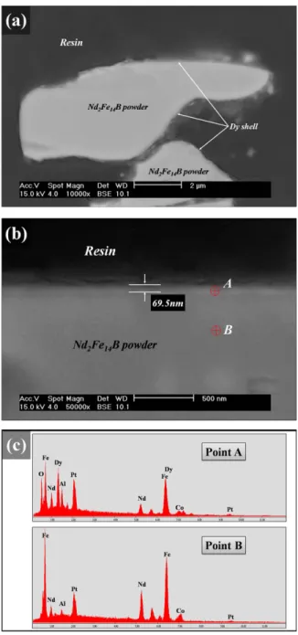
Fig. 2(a) and (b) show cross-sectional SEM (BSE) images of the coated powder, while Fig. 2(c) shows the EDS point analysis of the shell (point A) and core (point B) parts of the coated powder. A Dy sputter coating pro- cess was applied for 2.48 wt% on this core powder, resulting in whitish gray shell structures, which were Fig. 1. (a) Sputtering equipment used for the Nd-Fe-B powder
coating, (b) ideal core-shell powder shapes (upper diagram) and microstructures obtained when the core-shell powder was sintered (lower diagram).
assumed to be a different phase, formed on the gray Nd2Fe14B core powder. The thickness of the Dy shell was approximately 69.5 nm, as indicated in Fig. 2(b). The formation of Dy-shell structures by the sputter coating process was confirmed by EDS point analysis, which showed evidence of the presence of Dy (Fig. 2(b), point A) and of the reduction of the relative Fe and Nd con- tent compared to the core section (Fig. 2(b), point B).
Therefore, proper microstructure control at the initial powder stage can facilitate the formation of Dy shells on Nd2Fe14B cores during the final sintering step.
Fig. 3 shows SEM (BSE) images of the sintered pow- der with different Dy contents. When compared to a sin- tered sample using non-coated powder (Fig. 3(a)), the sample using Dy-coated powder (Fig. 3(b)) showed a continuous Nd-rich phase connecting the grain bound- aries. Fig. 4 shows demagnetization curves of the Dy- coated specimens and a non-coated sintered specimen.
Dy-coated specimens had reasonably higher coercivity and lower remanence than non-coated ones.
In general, the remanence of the Dy2Fe14B phase was lower than that of the Nd2Fe14B phase. The total rema- nence of the (Nd,Dy)-Fe-B magnets decreased as a result of the increase in Dy2Fe14B phase with Dy content [6, 7, 9]. In the Dy-coated specimens, the remanence did not decrease greatly compared to the non-coated sintered specimen. As shown in Table 1, such a minimal decrease in remanence seems to be due to the increase in total rare earth due to the added Dy content. In this case, even though the remanence was decreased due to the increase in both the total rare earth material and the Dy content, it was still superior to others with similar compositions [6].
In particular, after heat treatment, the coated specimen showed a noticeable improvement in the coercive value Fig. 2. Analysis of the microstructure of the powder produced
by the sputter coating process: (a) and (b) cross-section SEM (BSE) images, and (c) EDS point mapping images of the shell (point A) and core (point B) parts of the coated powder.
Fig. 3. SEM (BSE) images of the sintered powder at different Dy content: (a) 0 wt%(non-coated) and (b) 2.48 wt% (coated).
of 858.28 kA/m as compared to the non-coated specimen.
The coercivity of Dy-coated specimens increased remarkably after heat treatment. Comparably, the non- coated specimens also showed an increase in coercivity of 226.04 kA/m. It has been previously reported that the increase of coercivity with around 2.5 wt% Dy content is 400-450 kA/m [10]. However, in the case of the coated specimen, the coercivity increased over two times com-
pared with that of a conventional Dy-alloyed magnet.
The remarkable increase in coercivity of the coated spec- imens can be attributed to the sintering of the powder component of the fabricated core-shell structure caused by the heat treatment process. During this process, an exchange between the Nd2Fe14B phase of the core and the Dy phase of the shell occurred, thereby forming a (Nd,Dy)2Fe14B phase at the grain boundary [10]. In gen- eral, this phase formed at the grain boundary shows a larger HA than does the core phase, thus enhancing the Hci values of the Nd-Fe-B magnets [6].
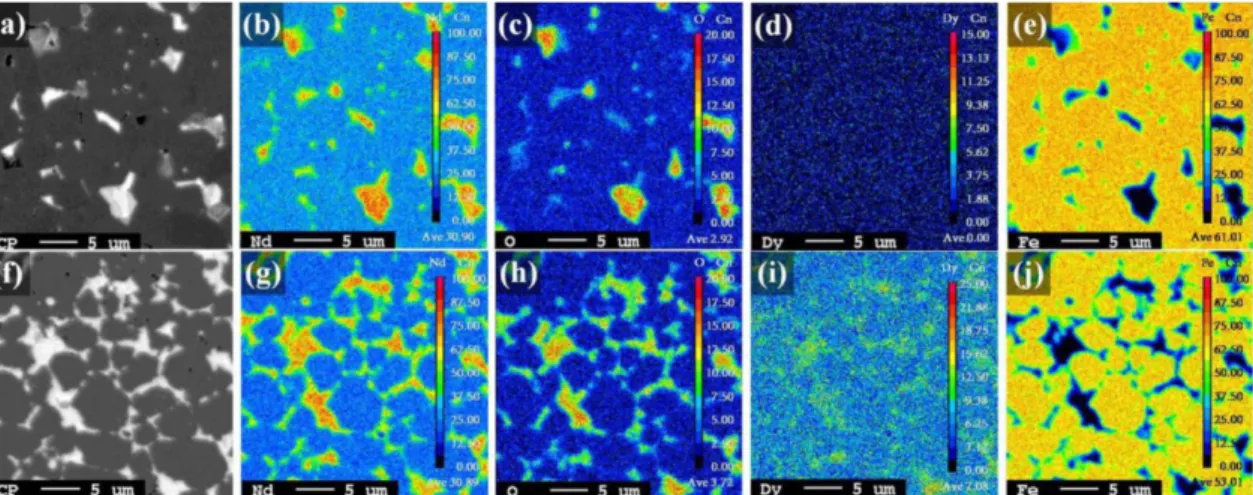
Fig. 5 shows SEM images of non-coated and Dy- coated specimens (2.48 wt%) and a related EPMA map- ping image. The microstructures in the BSE image in Figs. 5(a, f) are typical of a Nd-Fe-B sintered magnet, and they consist of a Nd2Fe14B main phase (gray color) and a Nd-rich interface phase (white color). Figs. 5(b-e and g-j) show the EPMA mapping results for non-coated and Dy-coated specimens (2.48 wt%).
The Dy-coated specimens show Nd-rich (NdOx) phases infiltrating along the Nd2Fe14B grain boundaries (continuous GBP phase). Furthermore, because the grain Table 1. Magnetic properties, total rare earth content, and relative density of each sample
Process Specimen Dy
(wt%)
Nd (wt%)
Total RE (wt%)
Hci (kA/m)
Br (T)
(BH)max (MGOe)
Density (g/cm3)
Non-coated As sintered 0 32 32 936.38 1.39 47.4 7.64
After HT 0 32 32 1162.42 1.39 47.55 7.64
Coated As sintered 2.48 31.2 33.68 1075.16 1.31 42.40 7.64
After HT 2.48 31.2 33.68 2020.70 1.30 42.75 7.64
*HT: Heat treatment, *Theoretical density: 7.68 g/cm3
Fig. 4. Demagnetization curves of non-coated and Dy-coated specimens with heat treatment (HT).
Fig. 5. Secondary electrons image and EPMA mapping results of non-coated (a-e) and Dy-coated specimens (f-j): (a), (f) back- scattered electrons image, mapping image of (b, g) Nd, (c, h) O, (d, i) Dy, and (e, j) Fe.
boundaries of the Nd-rich (NdOx) phases are surrounded with Dy, a (Nd,Dy)2Fe14B phase may be formed. In non- coated specimens, however, the Nd2Fe14B (hard magnet phase) cannot be isolated fully due to the Nd-rich, which exists locally in the triple junction phase.
The results presented in Figs. 4 and 5 clearly indicate that the powder fabricated by our sputter coating process effectively isolated the surroundings of the Nd2Fe14B core phase, resulting in a new material with improved coercivity characteristics. Both the addition of a heavy RE element such as Dy and the formation of a (Nd,Dy)2Fe14B phase are likely to restrain the antiferromag- netic coupling of Dy atoms with Fe atoms. In addition, it has been suggested previously that this (Nd,Dy)2Fe14B phase plays an important role in decreasing the nucleation sites of reverse domains and in the isolation of Nd2Fe14B grains [11].
4. Conclusions
This study describes a Dy sputtering process for coat- ing Nd2Fe14B powders with Dy to manufacture high- coercivity (Nd, Dy)-Fe-B sintered magnets in the form of core-shell structures. These magnets showed high rela- tive density (99%) and coercivity (2020.70 kA/m) values while preserving an average remanence of 1.32 T. A comparison of these values to those obtained for non- coated samples revealed a similar relative density and remanence values and an enhanced coercivity. Further- more, the (Nd,Dy)2Fe14B shell layer, which formed effec- tively around the Nd2Fe14B phase along the grain boundaries, completely enhanced the anisotropy field of the hard magnet phase, while the continuous (Nd,Dy)2Fe14B
phase contributed to the increase in coercivity.
Acknowledgments
− This work was supported by the Strategic Core Mate- rial Technology Development Program (No. 10043780) funded by the Ministry of Knowledge Economy (MKE, Korea).
− This work was supported Korea Institute for Rare metals (KIRAM) funded by Korea Institute of Industrial Technology (KITECH, Korea)
References
[1] M. Sagawa, S. Fujimura, N. Togawa, H. Yamamoto and Y. Matsuura: J. Appl. Phys., 55 (1984) 2083.
[2] H. J. Wang, Z. H. Guo, A. H. Li, X. M. Li and W. Li: J.
Magn. Magn. Mater., 303 (2006) e392.
[3] M. Soderznik, K. Z. Rozman, S.Kobe and P. McGuiness:
Intermetallics., 23 (2012) 158.
[4] W. F. Li, T. Ohkubo, K. Hono and M. Sagawa: J. Magn.
Mater., 321 (2009) 1100.
[5] I. D. Kosobudskii, V. P. Sevostyanov and M. V. Kuz- netsov: Inorg. Mater., 36 (6) (2000) 584.
[6] W. Q. Liu, H. Sun, X. F. Yi, X. C. Liu, D. T. Zhang, M.
Yue and J. X. Zhang: J. Alloys Compd., 501 (2010) 67.
[7] K. Hirota, H. Nakamura, T. Minowa and M. Honshima:
IEEE Trans. Magn., 42 (10) (2006). 2909.
[8] C. H. de Groot, K. H. J. Buschow and F. R. de Boer: J.
Appl. Phys., 83 (1998) 388.
[9] Gaolin Yan, P. J. McGuiness, J. P. G. Farr and I. R. Harris:
J. Alloys Compd., 491 (2010) L20.
[10] Fang Xu, Lanting Zhang, Xianping Dong, Qiongzhen Liu and Matahiro Komuro: Scr. Mater., 64 (2011) 1137.
[11] K. Raviprasad, M. Funakoshi and d M. Umemoto: J.
Appl. Phys., 83(2) (1998) 921.