반도체디스플레이기술학회지 제15권 제3호(2016년 9월)
Journal of the Semiconductor & Display Technology, Vol. 15, No. 3. September 2016.
로봇팔 타입 삼차원좌표측정기를 이용한 광학계의 비축수차 보정
전호빈*^김고은*^송인웅**^강혁모**^이혁교**†^김영식**^양호순**^권종훈***
*과학기술연합대학원대학교 측정과학과,
**†한국표준과학연구원 우주광학센터, ***LG이노텍
Coma Aberration Correction of Optical System by using a Robot Arm Type Coordinated Measuring Machine
Ho Bin Chun
*, Goeun Kim
*, In-Woong Song
**, Hyug-Mo Kang
**, Hyug-Gyo Rhee
**†, Young-Sik Ghim
**, and Ho-Soon Yang
**and Jong Hoon Kwon
****Department of Science of Measurement, University of Science and Technology,
**†Center for Space Optics, Korea Research Institute of Standards and Science, ***LG Innotek
ABSTRACT
Optical system needs to be aligned before its undergoing process, is usually shows coma aberrations, which occurred due to imperfection in the lens or other components results in off-axis point sources, appearing to have a tail like a comet. There are some methods to correct coma aberration. In this paper, to correct coma aberration in optical system, using a robot arm type coordinate measuring machine(CMM). CMMs are widely used to measure the form of accuracy of parts and positioning accuracy of systems. Among them, robot arm type CMM has more advantages than the others, such as its mobility and measuring range. However, robot arm type CMM has lower accuracy than cantilever type CMM. To prove robot arm type CMM’s accuracy, several factors were suggested in this paper and the final measuring results were compared to a commercial cantilever type CMM. Based on this accuracy, a typical optical system was successfully aligned by using our robot arm type CMM.
Key Words : aberration correction, coordinate measuring machine, robot arm, alignment
1. 서 론1
반도체 및 디스플레이 분야에서 사용하는 노광용 광학 계의 경우 수차가 거의 없도록(고해상도 광학계의 경우 파면오차 30 nm rms이내) 정렬 및 조립이 이루어져야 높은 정도의 노광 분해능을 얻을 수 있다. 비단 노광용 광학계 뿐 아니라 프로젝션 디스플레이용 광학계나 카메라 조립 체의 경우도 광학계의 수차를 제거하는 방향으로 광학계 조립 및 정렬이 이루어져야 해상도 저하를 방지할 수 있
†E-mail: [email protected]
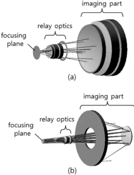
다. 이러한 광학계들 가운데 상당수는 Fig. 1과 같이 상을 맺기 위한 결상부(imaging part)와 상을 전달하고 초점을 조절하는 전달부(relay optics)로 나뉘어 지는데, 광학계의 조립 과정에서는 결상부와 전달부 광학계를 각각 완성한 다음 다시 이 두 개의 광학계를 조립하는 과정을 거치게 된다. 이 때 결상부 광학계에 대해 전달부 광학계가 기울 어지거나(tilt) 광축에 대해 좌우로 어긋나는 경우 (de- center) 비점수차(coma aberration)가 주로 발생하며, 이 수 차가 Fig. 2에서 보는 바와 같이 결상성능(노광용 광학계 의 경우 노광성능)에 악영향을 미친다.
로봇팔 타입 삼차원좌표측정기를 이용한 광학계의 비축수차 보정 63
Fig. 1. Typical optics configuration of an (a) all-lenses-type- and a (b) combined-type-optical system.
Fig. 2. Point spread functions (a) with and (b) without coma aberration.
이상의 문제를 최소화하기 위해 간섭계를 이용하여 수 차를 최소화하는 조립/정렬 연구들이 기존에 수행되어 왔 으나1-4 이 연구들은 축상(on-axis) 및 비축(off-axis) 측정을 수 차례 반복해야 비로소 조립/정렬이 가능하다는 단점이 있다. 따라서 본 논문에서는 기존 연구들의 한계를 극복 하고 빠른 시간에 결상부와 전달부 광학계를 조립하기 위해 로봇팔 타입의 삼차원좌표측정기(coordinate measuring machine)5-8를 적용해 보았다.
Fig. 3. Coordinate measuring machines, (a) cantilever type, (b) robot arm type, and (c) its photograph view.
일반적으로 삼차원좌표측정기는 정밀측정이 필요한 분야에서 널리 사용되고 있으며 통상적으로 5~10 µm 수준 의 정확도를 갖는다. 하지만 복잡한 광학계를 조립/정렬 하기 위해서는 측정 프로브(probe)가 x, y, z축으로만 움직 일 수 있는 기존의 캔틸레버식 삼차원좌표측정기는 적용 이 불가능하고, Fig 3(b)와 같이 움직임이 자유로운 로봇팔 타입 좌표측정기를 사용할 수밖에 없다. 로봇팔 타입의 삼차원좌표측정기는 광학계의 수차 측정용 간섭계가 설 치된 상태에서도 광학계 각 부품의 좌표 측정을 병행할 수 있어 활용도가 높다. 다만 로봇팔 타입의 삼차원좌표 측정기의 정확도는 기존의 캔틸레버식 삼차원좌표측정기 보다 떨어지기 때문에 반드시 로봇팔 타입 삼차원좌표측 정기에 대한 비교/검증 실험이 선행되어야 한다.
이상의 목적에 따라 본 연구에서는 우선 로봇팔 타입 의 삼차원좌표측정기를 검증하기 위한 실험을 수행했다.
그 다음 실제 광학계에 대해 결상부와 전달부 광학계를 정렬하기 전 파면 상태를 간섭계로 측정하고, 전산모사를 통해 전달부 광학계가 결상부 광학계에 비해 얼마나 tilt 와 de-center가 발생했는지 계산한 다음, 로봇팔 타입의 삼차원 좌표측정기로 전달부 광학계를 측정하면서 정렬 (alignment)하여 이 tilt와 de-center가 최소화되도록 조정했 다. 그 후 다시 간섭계로 광학계 전체의 수차를 측정하여 비점수차가 얼마나 줄어들었는지 살펴보았다.
2. 로봇팔 타입 삼차원좌표측정기 정밀도 검증
로봇팔 타입 삼차원좌표측정기로 광학계 정렬을 하기 전에, 이 측정기가 삼차원 공간 상에서 얼마나 정밀한지 검증하는 실험을 수행했다. 보다 정밀한 검증을 위해 본 연구에서는 우선 Fig. 4와 같이 진원도가 우수한 기준 구 (reference sphere)를 제작한 다음, 로봇팔 타입 삼차원좌표 측정기로 기준 구의 표면을 4점 이상 측정하여 구의 중심 좌표를 얼마나 정확하게 측정하는지 살펴보았다.
Fig. 4. Factors of measuring uncertainty (a) size of ball-tip, (b) measuring area, and (c) number of contact points.
전호빈 · 김고은 · 송인웅 · 강혁모 · 이혁교 · 김영식 · 양호순 · 권종훈 64
삼차원좌표측정기로 기준 구를 측정할 때 측정정확도 에 영향을 미칠 수 있는 인자는 다음 Fig. 5와 같다. 첫째, 측정프로브의 볼 팁(ball-tip)의 지름, 둘째, 측정점의 분포 각도, 셋째, 구의 중심을 계산하기 위해 사용한 점의 개수 가 바로 그것이다.9
먼저 기준 구를 로봇팔 타입의 삼차원좌표측정기로 측 정하기 전에 표준기로부터 교정을 받은 캔틸레버식 삼차 원좌표측정기(반복측정불확도 5 µm @ 700 mm X 800 mm X 500 mm, ball-tip 지름: 3 mm)에서 이 기준 구의 지름을 10회 반복 측정했을 때 결과는 Fig. 5에 도시했다. 이어서 로봇팔 타입의 삼차원좌표측정기의 볼 팁 지름을 각각 3 mm, 6 mm로 바꿔가며 10회 측정한 결과는 Fig. 5에서 보듯 이 평균 59.99 mm(3 mm ball-tip), 62.14 mm(6 mm ball-tip) 표준편차 0.022 mm(3 mm ball-tip), 0.104 mm(6 mm ball-tip) 로 얻어졌다. 이 결과 프로브의 볼 팁 지름을 3 mm로 선택 하는 것이 더 정확한 측정결과를 준다는 결론을 얻었다.
Fig. 5. Effects of the ball-tip diameter; experimental results were obtained by a cantilever type coordinate measuring machine with a 3-mm-diameter ball-tip probe, a robot arm type coordinate measuring machine with a 3-mm-, and a 6-mm-diameter ball- tip probe.
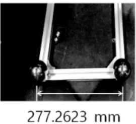
Fig. 6. Reference distance bar for experiment of uncertainty.
둘째, 측정점 분포 각도에 따른 영향을 실험적으로 알 아보기 위해 본 연구에서는 Fig. 6과 같이 두 개의 기준 구 를 일정한 거리에 고정한 다음, 캔틸레버식 삼차원좌표측 정기와 로봇팔 타입 삼차원좌표측정기로 이 두 기준 구
의 중심좌표를 측정하여 중심좌표 사이의 거리를 비교해 보았다. 이 때 로봇팔 타입 삼차원 좌표측정기로 기준 구 의 중심좌표를 측정할 때 Fig. 4(b)와 같이 구의 꼭지점 부 분을 기준으로 30°부터 180°까지 각각 30°의 변위 값을 주 고 측정하여 그 결과를 관찰했다. 두 개의 서로 다른 삼 차원좌표측정기로부터 얻은 거리 측정값은 Fig. 7(a)와 같 이 얻어졌으며, 분포 각도가 60°이상이면 만족할 만한 측 정값을 얻을 수 있다는 결론을 내렸다. 이 때 삼차원좌표 측정기의 볼 팁 지름은 두 가지 타입 모두 3 mm 로 선택 했다.
Fig. 7. Distance difference in (a) measuring area and (b) number of contact points, At these experiments the number of measurement was 10 at each datum.
셋째, 측정점 개수에 따른 영향을 알아보기 위해 Fig. 6 의 측정치구를 대상으로 기준 구의 중심좌표 사이의 거 리를 반복 측정했다. 이 때 중심좌표 계산을 위한 측정점 의 개수를 4개부터 9개까지 바꿔가면서 그 영향을 살펴 보았으며, 측정 분포 각도는 60°, 볼 팁 지름은 3 mm로 고 정했다. Fig. 7(b)에서 보는 바와 같이 로봇팔 타입 삼차원 좌표측정기로 기준 구의 중심좌표를 계산 할 때 5개 이상 의 측정점을 사용하면 측정정밀도가 기존의 캔틸레버식 좌표측정기에 근접하는 것을 알 수 있다.
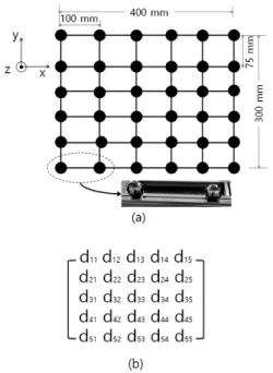
이상의 기초 실험 결과에 따라 볼 팁 지름은 3 mm, 측 정 분포 각도는 60°, 좌표 한 점을 계산 할 때 사용하는 측정점 개수는 5개로 고정한 상태에서 로봇팔 타입의 삼 차원좌표측정기가 삼차원 공간 상에서 어느 정도의 정확 도를 갖는지 실험해 보았다. 먼저 Fig. 8과 같은 6 X 6개의 기준 구로 이루어진 2차원 측정치구를 제작하여 캔틸레 버식 삼차원좌표측정기에서 이 기준치구의 거리 좌표를 측정했다. 기준 구가 6 X 6이므로 실제 구의 중심좌표 사 이 거리는 Fig. 8(b)와 같이 5 X 5매트릭스로 표시할 수 있 다. 본 연구에서는 실제로 측정하게 될 실제로 측정하게 될 광학계의 크기를 고려하여 400 mm X 300 mm 의 측정치 구를 제작하였으며, 정밀 스테이지에 이 치구를 장착하여 z 방향으로 75 mm 씩 이동하면서 5 X 5 행렬을 3번 측정하 여 400 mm X 300 mm X 150 mm의 공간 안에서 로봇팔 타입
로봇팔 타입 삼차원좌표측정기를 이용한 광학계의 비축수차 보정 65
Fig. 8. Reference structure for volumetric accuracy test (a) experimental structure and (b) distance matrix; the symbol d represents a distance between two reference spheres.
삼차원좌표측정기의 측정오차 분포를 조사했다.
Fig. 9는 Fig 8(b)의 각 기준 구 사이 거리를 로봇팔 타입 의 삼차원좌표측정기와 캔틸레버식 삼차원좌표측정기로 각각 측정한 다음, 그 편차를 그림으로 나타낸 결과다. 캔 틸레버식 삼차원좌표측정기의 반복측정불확도가 5 µm이 므로, Fig. 9의 결과는 로봇팔 타입 삼차원좌표측정기의 공 간 오차 분포로 볼 수 있으며, 이 실험을 통해 로봇팔 타 입 삼차원좌표측정기를 측정대상으로부터 z 방향으로 290 mm 떨어뜨려 놓고 측정했을 때 400 mm X 300 mm 공간 영역에서 70 µm 이내의 측정정확도를 갖는다는 결론을 얻었다.
Fig. 9. Volumetric error map of the robot arm type coordinate measuring machine.
3. 광학계 정렬 실험
3.1 정렬전 수차 측정 및 전산모사를 통한 tilt 및 de-center 예측
대상 광학계의 결상부와 전달부를 1차 가조립한 상태 에서 간섭계로 전체 광학계의 파면을 측정하면 Fig. 10(a) 와 같으며, 결상된 광의 FWHM(Full Width Half Maximum) 은 약 5.0 µm였다. 이 때 비점수차는 123 nm rms로 측정되었다.
Fig. 10. Wave front error of aberration before align; (a) wave front error, and (b) point spread function.
위의 비점수차 값을 바탕으로 상용화된 Code-V 소프트 웨어10를 사용하여 전산모사한 결과 전달부 광학계가 결 상부에 비해 x = 10 µm, y = -0.004 mm, tilt는 x = 0.012°, y = 0.029°
어긋났다는 계산결과를 얻었다. 또한 전달부 광학계를 x
= 0.007 mm, y = -0.002 mm, tilt는 x = 0.011°, y = 0.031°로 조정하 면 전체 광학계의 비점수차를 이론상 0으로 만들 수 있다 는 결과를 획득했다.
3.2 전달부 광학계 정렬
위 전산모사 결과에 따라 간섭계로 대상 광학계의 파 면 수차를 모니터링하면서 전달부 광학계의 공간상 위치 를 조정(x = 7.0 µm, y = -2.0 µm, tilt는 x = 0.011°, y = 0.031°)하였 으며, 이 때 로봇팔 타입 삼차원좌표측정기로 수치를 확 인했다. 최종 정렬 결과는 Fig. 11의 파면과 같으며, 이 가 운데 비점수차 성분은 4.2 nm로 거의 사라졌다. 물론 전산 모사의 결과처럼 비점수차를 0으로 소멸시킬 수는 없었 으나, 이는 실험과 전산모사의 차이에서 기인하는 값으로 산업 현장에서 충분히 허용될 수 있는 수치이다. 또한 이 때 point spread function의 FWHM은 약 1.1 µm였다.
Fig. 11. Wave front error after align; (a) wave front error, and (b) point spread function.
전호빈 · 김고은 · 송인웅 · 강혁모 · 이혁교 · 김영식 · 양호순 · 권종훈 66
4. 결 론
본 연구에서는 로봇팔 타입의 삼차원좌표측정기와 전 산모사를 이용하여 광학계의 비축수차를 기존 방법에 비 해 빠르게 보정할 수 있는 방법을 제안하고, 실험을 통해 이를 검증했다. 또한 로봇팔 타입 삼차원좌표측정기를 기 존의 교정된 캔틸레버식 삼차원좌표측정기와 비교 실험 함으로써 이 측정기의 공간 상 오차 지도를 획득하였고, 이를 통해 로봇팔 타입 삼차원좌표측정기의 오차를 최소 화 한 상태에서 사용할 수 있는 조건을 제시했다.
감사의 글
본 논문은 국과과학기술위원회의 CAP 과제 (CAP-12-05- KRISS)의 지원으로 작성되었습니다.
참고문헌
1. Yunjong Kim, H.-S. Yang, J.-B. Song, S.-W. Kim, Y.-W.
Lee, “Modeling alignment experiment errors for improved computer-aided alignment,” Journal of the optical society of korea, Vol. 17, No. 6, pp. 525-532, 2013.
2. J. Liu, F. Long, and W. Zhang, “Study on computer-aided alignment method,” Proc. SPIE 5638, pp. 674-681, 2005.
3. D. C. Redding, N. Sigrist, J. Z. Lou, Y. Zhang, P. D.
Atcheson, D. S. Acton, and W. L. Hayden, “Optical state
estimation using wavefront data,” Proc. SPIE 5523, pp.
212-224, 2004.
4. S. Kim, H.-S. Yang, Y.-W. Lee, and S.-W. Kim, “Merit function regression method for efficient alignment control of two-mirror optical systems,” Opt. Express 15, pp. 5059-5068, 2007.
5. S.P. Lee, H.J. Kang, and S.K. Ha, “An experimental study on the measurement performance of coordinate measuring machine,” J. Kor. Soc. Pre. Eng., Vol. 26, No.
3, pp. 47-54, 2009.
6. H.-G. Rhee, H.. Yang, I. Moon, Y.. Kim, Y. Lee, J. Bae, K.
Park, and Y. Choi, “High quality EO/IR camera for an airborne application,” Proc. of KSPE fall conference, pp.
541-542, 2011.
7. Y. Koo, and D. Lee, “Development of a CAM system for mold machining using 3D measurement data,” J. Kor.
Soc. Mach. Tool Eng., Vol. 7, No. 4, pp. 79-88, 1998.
8. J. Lee, Y. Lee, J. Choi, “Optical measuring instrument and its application for 3D coordinate measurement,” J.
KSME, Vol. 40, No. 5, pp. 65-68, 2000.
9. ASME B89.4.22-2004, Methods for performance evaluation of articulated arm coordinate measuring machines (CMM), New York, 2004.
10. https://optics.synopsys.com/codev/
접수일: 2016년 9월 1일, 심사일: 2016년 9월 20일, 게재확정일: 2016년 9월 21일