밀리미터파 무선통신 시스템에서의 빔포밍 기법 성능 평가
Thanh Ngoc Nguyen*, 전태현* 정회원
Performance Evaluation of Beamforming Scheme in Millimeter Wave Wireless Communication System
Thanh Ngoc Nguyen*, Taehyun Jeon* Regular Member
요 약
실내 고속 데이터 전송을 목표로 하는 밀리미터파 무선통신 시스템은 고 품질의 무선 링크에 대한 요구 사항이 매우 중요하다. 그러 나, 이러한 주파수 대역에서 전자기파는 상대적으로 작은 파장으로 인하여 발생하는 높은 전파 손실을 감수해야 한다. 이러한 상황에 서 방사전력을 특정 방향으로 집중하여 링크 품질을 향상시킬 수 있는 빔포밍 기법은 밀리미터파 대역 무선통신에서 가장 중요한 기법 중의 하나가 되었다. 최근 몇 년간, 무선 시스템의 성능을 향상시키기 위한 빔포밍 관련 연구가 많이 이루어지고 있다. 본 논문 에서는 다중절차와 3상 빔 선택을 기반으로 한 단순화된 코드북 기반의 빔포밍 기법의 성능을 평가한다. 이 단순화된 기법은 전수검 색, IEEE 802.15.3c 표준이 적용된 2-레벨 검색 및 기존의 멀티레벨 기법과 비교하여 빔포밍 준비에 필요한 시간 감소를 달성할 수 있음을 보여준다.
Key Words : Beamforming, mmWave, codebook, sector, beam
ABSTRACT
Millimeter wave wireless communication systems, especially those targeting indoor high rate data transfer, have a strong requirement for high quality wireless link. Unfortunately, in this frequency band, the electromagnetic wave has to sustain the high propagation loss caused by the smaller wavelengths. In this scenario, beamforming technique, which enhances the link quality by focusing the radiation power on a direction, becomes one of the most important techniques in millimeter wave band wireless communication. In recent year, there been conducted many research on beamforming to improve the performance of wireless system. In this paper, we evaluate the performance of a simplified codebook-based beamforming scheme which is based on multiple-procedure and three-state beam selection. The simplified scheme significantly reduces beamforming setup time, comparing to the exhaustive searching, two-level searching adopted in IEEE 802.15.3c standard, and also conventional multi-level scheme.
※ 이 연구는 서울과학기술대학교 교내연구비의 지원으로 수행되었음.
*서울과학기술대학교 전기정보공학과, 교신저자: 전태현 ([email protected]) 접수일자 : 2016년 9월 26일, 최종게재확정일자 : 2016년 9월 29일
I. Introduction
Millimeter wave (mmWave) band communication, especially the 60GHz band, has received more and more attention in indoor applications. One of the most attractive advantages of mmWave communication is the capability to achieve multi-Gbps to support high rate data transfer applications. However, mmWave communication suffers from high propagation loss because of the absorption in air environment. In order to combat the propagation loss and
improve the link quality, multiple element array antenna is favored to improve the system efficiency and transmission range. Moreover, since the dimensions and necessary spacing of 60GHz antennas are in the order of millimeters [1], multiple antennas can be integrated into portable devices. It makes possible to implement the MIMO techniques, particularly beamforming, in wireless systems.
Beamforming technique shapes the pattern of multiple antennas into beam and directs it toward a certain direction to maximize the transmission power. The
antenna gains of the transmitter (Tx) and the receiver (Rx) have significant impact on the transmission data rate.
To achieve this goal, beamforming protocol is required to determine the best transmit and receive beams among a predefined codebook, according to the selection metric such as signal to noise ratio (SNR) or signal to interference plus noise ratio (SINR). Due to the increase of system scale, such as number of antennas and number of available beams, it requires a long training period to estimate the best beam pair. This problem may cause the performance degradation for the channels that vary in time quickly.
In this paper, we consider a beamforming scheme called three-state scheme which is based on two basic techniques: (1) multi-level procedure, which is mentioned in several research works [2], [3] and (2) our previous work, three-state beam selection method, which can use information from nearby beams to infer the signal power level from the center beam. The principle of three-state beam selection method is described in detail in [4]. In this paper we follow the guideline specified in IEEE 802.15.3c standard to further evaluate the performance of the beamforming scheme in term of setup time and also accuracy. The remainder of this paper is organized as follows. In section II, the description the beamforming system is presented. The conventional and the three-state schemes are discussed in this section. The main content is in section III which describes the simulations and discusses the result. Finally, conclusions are given in section IV.
Ⅱ. Beamforming System
1. Beamforming Model
We consider a beamforming (BF) system in a piconet, it can be the connection between a piconet coordinator (PNC) and a device (DEV) or two devices (DEV to DEV).
In detail, our system is asymmetric antenna system (AAS) specified in standard [1] where DEV1 has transmit antennas and receive antennas. Similarly, and are the number of transmit and receive antennas, respectively. For the link from DEV1 to DEV2, at the transmitter of DEV1 the signal after baseband processing is up-converted into radio frequency (RF) band and divided into signal. The RF band signal is phase shifted according to the DEV1’s transmit weight vector,
and then emitted to the free space. At the DEV2’s receiver, the received RF signals are phase-shifted by the DEV2’s receiver weight vector then combined and down-converted into baseband for further processing.
With reverse link from DEV2 to DEV1, the same operation would be conducted. Transmit and receive weight vectors of both DEV1 and DEV2 are selected from the pre-defined matrix called codebook. The general purpose of beamforming protocol is selecting transmit and receive weight vectors for devices to optimize a cost function as a performance metric. In this paper, we adopt the signal-to-interference-plus-noise ratio (SINR) as a cost function which is calculated in [5].
2. Conventional Beamforming Scheme
In this section, we briefly introduce the beamforming scheme adopted in standard IEEE 802.15.3c [1] which is developed in millimeter wave band for the existing Wireless Personal Area Network (WPAN). This beamforming scheme includes two training levels: sector training with wide patterns and beam training level with finer beam. First of all, the best sector pair is determined in the sector level training, and then the beam level training finds the best beam pair in the interest area which is dedicated in sector level training. At each level, there are four stages: 1) training stage, 2) feedback stage, 3) mapping stage, and 4) acknowledgement stage. Fig. 1 illustrates the timing diagram of sector training that is specified in [1]. As mentioned in the previous section, we consider the beamforming procedure between two DEVs in a piconet. Let us assume that DEV1 has and sectors, for transmitting and receiving respectively.
Similarly, DEV2 has transmit sector and receive sectors. The training procedures consist of
cycles and DEV1 transmits repetitions of a training sequence in the same direction during each cycle. DEV2 receives the training sequence using a different direction during each cycle and selects the best sector pair to optimize the cost function after finishing the
cycles. The information about selected sector is feedback between 2 devices in feedback stage. Therefore, after finishing this stage, each device knows about its own best transmit and receive sector and also the partner’s ones.
The selected best sector pairs are divided into number of beams for the fine beam training in the next level. The information about the number of beams is exchanged in
mapping stage, and acknowledgement stage will complete the sector level training. In the beam level training, the best beam pair is found with the same procedures as the sector level.
To further reduce the beamforming training time, the authors in [2] proposed a new beamforming scheme which includes 3 training levels (add omni level training to narrow down the interest area for sector training level). In summary, beamforming can reduce the searching time dramatically, when we divide the beam searching procedure into multiple levels. However, in each sub-stages, exhaustive searching algorithm is used, that makes the training process takes a long time in large scale system which has a huge number of antenna and codebook size.
SIFS Sector training DEV1→DEV2 Sector training
DEV2→DEV1
SIFS
Sector training cycle #0 Sector training
cycle #1 Sector training
cycle #J(1,t)-1 ...
Sector training #0 Sector
training #1 Sector training
#J(2,r)-1 ...
BSIFS
Sector training Sector
feedback Sector beam
mapping Ack
Time
Fig. 1. Timing diagram of sector training in IEEE 802.15.3c.
3. Three-State Beamforming Scheme
In this section, three-state beamforming scheme will be described which is the combination of multi-level training procedure [2] and the three-state beam selection method [4]. This scheme divides the beamforming process into three stages based on the three kinds of radiation patterns:
quasi-omni level training (called DEV-to-DEV linking), sector level training and beam level training. Through above three stages, the devices will find the best beam for transmission and receiving. The first stage of beamforming process is quasi-omni level training which includes 4 sub-stages: quasi-omni pattern training, quasi-omni pattern feedback, quasi-omni to sector mapping and acknowledgement, as described in [2].
During the training process, the receiver observes the training sequences (TS), and select the best receive quasi-omni pattern of it and the best transmit quasi-omni pattern of the transmitter base on the estimated SINR.
The same training process is repeated in the opposite direction. After training period, two devices know its best receive quasi-omni pattern but they do not know their
own best transmit pattern, which is exchanged in the feedback stage. This information is sent by an announce command with implied acknowledgement (Imp-ACK) request. After that, the best transmit and receive are known at both two devices. The next sub-stage is quasi-omni to sector mapping, in which the information about the interest sectors is exchanged to prepare for the next step. Finally, an acknowledgement will be sent to finish the first stage of beamforming process.
After the first stage, the beamforming continuous with the sector level and beam level searching into which the three-state beam selection method is applied. In conventional multi-level searching scheme, we have to try all the sectors and the beams mapped by the selected quasi-omni pattern and the selected sector, respectively.
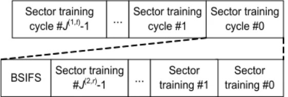
That will be time consuming as the number of sector and number of beam increase due to the system expansion. To reduce the number of training sequences, three-state beam selection method [4] is applied where we just consider the odd beams and the best beam can be inferred by the ratios of the best odd beam and the two adjacent odd beams. This method requires a predefined threshold to decide the best among three beams by considering the ratio of two side beams. As a result, in sector level and beam level training, we need only half number of training sequences to achieve information of odd sector and odd beam. Fig. 2 illustrates the sector training process with three-state beam selection method.
Sector training cycle #0 Sector training
cycle #1 Sector training
cycle #J(1,t)-1 ...
Sector training #0 Sector
training #1 Sector training
#J(2,r)-1 ...
BSIFS
Fig. 2. Timing diagram of sector training for three-state beam selection.
Ⅲ. Performance Evaluation
1. Beamforming Setup Time
In this part, we follow the guidelines of IEEE 802.15.3c criteria to estimate the beamforming setup time for the three-state scheme and compare it with conventional ones.
We adopt the codebook generation method introduced in [1] which enables beamforming in the RF domain without a high power consumption by using only specific phase shifts without examining the amplitude of the signal for
1-D uniform array antenna. This codebook generation method is to be used at both the transmitter and the receiver. Denoting the codebook set as W, each column specifies a beamforming weight vector, or in other words, specifies a combination for the phase shifters and amplitude controllers to create a respect radiation pattern.
The weight vector for element to generate a beam
is given by [1]. We assume that DEV1 as well as DEV2 have 64 beams for both transmit and receive. The 64 beams are separated into 16 sectors with 4 beams in each sectors. In the simulation, the three-state scheme is used to find the best sector and then the best beam.
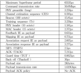
Fig. 3 shows the average setup time of several beamforming schemes for varying packet error rate (PER). The setup time is calculated by following the time schedule specified in standard [1] as illustrated in Fig. 1. The related MAC and PHY parameters are listed in Table 1. The result illustrates that the three-state scheme reduces the required time to estimate the best beams by half compared with the multi-level scheme.
Fig. 3. Beamforming setup time.
Maximum Superframe period 65535μs Command transmission rate 50.6Mbps
PHY preamble (long) 3.259μs
Channel estimation sequence (CES) 0.593μs
Beacon (100 octets) 15.81μs
Training sequence (Ts) 3.259μs PHY header (10 octets) 1.581μs MAC header (15 octets) 2.372μs Feedback IE as payload 0.632μs Mapping IE as payload 0.751μs Association request IE as payload 2.607μs Association response IE as payload 3.277μs
SIFS (TSIFS) 2.5μs
ACK (TACK) 7.212μs
Guard time (TGT ) 0.0625μs
Back off (Tbackoff ) 30μs
Payload size 2Kbytes
Payload transmission rate 1.619Gbps
Payload ACK policy No-ACK
Table 1. MAC related simulation parameters.
2. Effect of Wrong Beam Selection
In this part, we discuss in detail the simulation result to evaluate the accuracy performance of three-state scheme and compare it with the conventional schemes.
In this simulation, we consider the beamforming process at the receiver with the 1-D uniform spaced antenna array which consists of 32 element (M=32). The pattern codebook specfied by the IEEE 802.15.3c TG is utilized to generate 64 beam patterns (K=64). With IEEE 802.15.3c scheme, we assume the 64 beams in the codebook are divided into 16 sectors for the sector level training and 4 beams for each. Similarly, in multi-level scheme, we assume the number of quasi-omni is 4 and there are 16 beams divided into 4 sector for each quasi-omni. The effective spatial receiving range
is set to 9 degree.We use TSV channel model as shown in IEEE 802.15.3c [2]. In detail, channel mode CM1.4 (Residential LOS) is used, which contains strong LOS component except for the first-order NLOS clusters. In order to calculate the probability of the wrong beam selection, we first estimate the channel and calculate the SINR from equation in [5]
for a random DOA received by 64 beams in the codebook.
This procedure imitates the exhaustive searching, which gives the best beam with the highest SINR. Then, the simulation follows the procedure of three-state scheme and conventional one to get the best quasi-omni pattern, sector and finally the best beam. The best beams selected by each scheme are compared with the best beam selected by exhaustive searching which gives the optimal gain.
Fig. 4. CDF of gain loss.
We ran 10 thousand samples of the beam setup process for each scheme, and the three-state beam selection gives comparable performance with the exhaustive searching.
We also analysed the wrong selection cases. Fig. 4 illustrates the distribution of the gain loss due to the
wrong beam selection, where the X-axis denotes the gain loss below X dB with Y probability. In this figure, the gain loss is concentrated in the region from 0 to 1dB with the probability is more than 95%, that means, in almost cases, the gain loss caused by the false selection is relative small. Compared with the other multi-level training schemes, three-state requires the least searching time and maintains the reasonable gain.
Ⅳ. Conclusion
In this paper, the performance of the three-state scheme for codebook-based beamforming system is evaluated.
This scheme is the combination of multi-level training procedure and the three-state beam selection method for each training level. The simulation results show that three-state scheme reduces beam estimation time significantly compared to the standard scheme and other multi-level schemes while maintaining the gain level.
References
[1] IEEE Std., Wireless Medium Access Control (MAC) and Physical Layer (PHY) Specifications for High Rate Wireless Personal Area Networks (WPANs) Amendment 2, IEEE 802.15.3c, 2009.
[2] J. Wang, Z. Lan, C. Pyo, T. Baykas, C. Sum, M. Rahman, T. Baykas, J. Gao, R. Funada, F. Kojima, H. Harada, and S.
Kato, “Beam Codebook Based Beamforming Protocol for Multi-Gbps Millimeter-Wave WPAN Systems,” IEEE Journal on Selected Areas in Communications, vol. 27, no. 8, pp. 1390-1399, Oct. 2009.
[3] H. Lee, Y. Ko, Senior Member, “Low Complexity Codebook-Based Beamforming for MIMO-OFDM Systems in Millimeter-Wave WPAN,” IEEE Transaction on Wireless Communications, vol. 10, no. 11, pp. 3607-3612, Nov. 2011.
[4] T. Nguyen. and T. Jeon, “Three-State Search Algorithm for Codebook-Based Beamforming,” Information, vol. 19, no. 5, pp. 1407-1411, May 2016.
[5] B. Li, Z. Zhou, W. Zou, W. Sun, and G. Du, “On the efficient beamforming training for 60GHz wireless personal area networks,” IEEE Transaction on Wireless Communications, vol. 12, no. 2, pp. 504-515, Feb. 2013.
저자
Thanh Ngoc Nguyen
․2009년: Hanoi University of Science and Technology, School of Electronics and Telecommunication, Department of Biomedical Engineering 졸업(학사)
․2015년 ∼ 현재 : 서울과학기술대학 교 전기정보공학과 재학(석사) <관심분야> : Beamforming, 5G, wireless sensor network
전 태 현(Taehyun Jeon) 정회원
․1989년:연세대학교 전기공학과 졸업 (학사)
․1993년:미네소타대학교 전기공학과 대학원 졸업(석사)
․1997년:미네소타대학교 전기공학과 대학원 졸업(박사)
․1997년 ∼ 1998년:Motorola 연구원
․1998년 ∼ 2001년:Texas Instruments 연구원
․2002년 ∼ 2005년:한국전자통신연구원(ETRI) 선임연구원
․2005년 ∼ 현재:서울과학기술대학교 전기정보공학과 교수 <관심분야> : 유무선 통신시스템, 근거리 무선통신, 이동통신