†To whom corresponding should be addressed.
Tel : +82-43-750-1399 E-mail : [email protected]
https://doi.org/10.5855/ENERGY.2017.26.4.074
CO 2 sequestration and heavy metal stabilization by carbonation process in
bottom ash samples from coal power plant
Ramakrishna. CH
1, Thriveni. T
2,Seong Young Nam
3, Chunsik kim
4and Ahn Ji Whan
5*1,2
Hanil Cement, 302 Maepo-gil, Maepo-eup, Danyang-gun, Chungcheongbuk-do, Korea.
3,4
Technical Center, HANIL CEMENT Co.Ltd. 50, Daehwa-ro 52beonan-gil, Daedeok-gu, Daejeon, 34361, Republic of Korea.
5
Mineral Processing Division, Korea Institute of Geoscience and Mineral Resources (KIGAM), Gwahagno-124, Yuseong-gu, Daejeon, Korea.
(Received 20 November 2017, Revised 11 December 2017, Accepted 13 December 2017) Abstract
Coal-fired power plants supply roughly 50 percent of the nation’s electricity but produce a disproportionate share of electric utility-related air pollution. Coal combustion technology can facilitate volume reduction of up to 90%, with the inorganic contaminants being captured in furnace bottom ash and fly ash residues. These disposal coal ash residues are however governed by the potential release of constituent contaminants into the environment. Accelerated carbonation process has been shown to have a potential for improving the chemical stability and leaching behavior of bottom ash residues. The aim of this work was to quantify the volume of CO
2that could be sequestrated with a view to reducing greenhouse gas emissions and stabilize the contaminated heavy metals from bottom ash samples. In this study, we used PC boiler bottom ash, Kanvera reactor (KR) slag and calcined waste lime for measuring chemical analysis and heavy metals leaching tests were performed and also the formation of calcite resulting from accelerated carbonation process was investigated by thermo gravimetric and differential thermal analysis (TG/DTA).
Key words : Heavy metals, Carbonation, Coal power plant bottom ash
1. INTRODUCTION
Major environmental problems around the world are usually due to the disposal of waste materials such as industrial waste, construction waste, household waste and etc. However, industrial waste, also known as production by-products, has been investigated ex- tensively as sustainable alternatives to Portland ce- ment in concrete [1,2]. Recently, waste accumulation has become a major problem to the environment as well as human beings [3]. Heavy metals also con-
tamination in air, soil, and water is a global problem that is a growing threat to human beings. There are hundreds of sources of heavy metal pollution, includ- ing coal combustion in thermal power plants [4].
Bottom ash and fly ash produced during the combus- tion of coal contains several toxic heavy metals like arsenic (As), lead (Pb), nickel (Ni), zinc (Zn), nickel (Ni), etc. It is now a global concern to find environ- mentally friendly solutions for the safe disposal of industrial waste to sustain a cleaner and greener envi- ronment.
Coal ash is one of the biggest sources of industrial waste that is produced from power plant stations.
Cheriaf et al. [5] stated that 1.2 million metric tons
of coal ash have been produced during the combus- tion of 2.9 million metric tons of coal. Coal is wide- ly used in the production of electricity, steel and ce- ment manufacturing and is, therefore, an important source of energy. However, based on Bajare et al.
[6], several types of coal ash waste have been identi- fied such as bottom ash, fly ash, boiler slag, flue gas, desulfurized material and etc. Coal bottom ash and boiler slag are coarse, granular, incombustible materials that are collected from the bottom of coal burning furnaces. The majority of coal bottom ash and boiler slag are produced at coal-fired electric utility generation stations, with some coming from coal-fired boilers or independent coal-burning electric generation facilities. The type of bottom ash or boil- er slag produced depends on the type of coal-burning furnace.
Bottom ash is one of the well-known industrial waste that has been produced as a result of burning coal in a dry bottom pulverized coal boiler. Unburn- ed material from a dry bottom boiler consists of about 20 percent bottom ash. Bottom ash is a porous, glassy, dark gray material with a grain size similar to that of sand or gravelly sand [7]. Although similar to natural fine aggregate, bottom ash is lighter and more brittle and has a greater resemblance to cement clinker [8]. Boiler slag is the molten inorganic mate- rial that is collected at the bottom of the boilers and discharged into a water-filled pit where it is quenched and removed as glassy particles resembling sand.
When pulverized coal is burned in wet-bottom boil- ers (slag-tap boiler and the cyclone boiler), as much as 50 percent of the ash is retained in the slag tap furnace as boiler slag. In a cyclone furnace, 70 to 80 percent of the ash is retained as boiler slag, with on- ly 20 to 30 percent leaving the furnace in the form of fly ash [7,8].
Huge amounts of limestone are quarried and used worldwide for construction and landscaping purposes.
A large amount of waste is generated during cutting and sieving process of limestone which includes fragments, fine powder, and slurry. 60% to 70% of the stone is believed to be wasted in this process, of
which around 30% is believed to be fine powder [9].
A large amount of limestone waste generated from the processing has no useful utilization and is dis- posed of as waste, occasionally used for landfill pur- poses.
The products of the coal combustion process are flue gas and solid byproducts (e.g., fly ash particles, bottom ash, and boiler slag). Flue gas CO
2emissions from coal-fired power plants totaled 1718 Mt in the USA in 2011 [10]. Addressing the continuous rise of atmospheric carbon dioxide levels has become a fo- cus of global efforts. Research in carbon capture and storage (CCS) has increased substantially in the last decade [11,12]. Current carbon storage research has been primarily concentrated on sequestering CO
2in underground geologic formations such as saline aqui- fers, depleted oil and gas fields, and unmiserable coal seams. These methods of geologic sequestration have the advantage of being the relatively low cost when separated from CO
2capture, separation, and trans- portation. However, potential issues associated with sequestration in geologic formations include perma- nence, long-term monitoring, and verification, with many unknown effects and potential risks still to be determined [13,14]. An alternative to conventional geologic sequestration is carbon mineralization, where CO
2is reacted with metal cations such as magne- sium, calcium, and iron to form carbonate minerals.
The literature to date indicates that in the coming decades mineral carbonation can play an important role in rebalancing the global carbon cycle and pro- viding a long-term carbon storage solution [15,16]
and the carbonation process can reduced heavy metal
from the carbonated materials. Heavy metal ex-
traction should be considered seriously for usage of
carbonated materials since carbonation seriously ef-
fects on precipitation of minerals and contaminant
leaching through neutralization. To reduce the heavy
metal leaching on the carbonation process is the pH
neutralization and formation of new materials from
the raw minerals. Lowing pH to 8~9 minimizes dis-
solution of metal oxides [17] and physical changes
of the waste material structures and the extraction
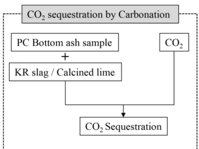
Fig. 1. CO
2sequestration process by carbonation method.
characteristics and mechanical properties. The carbon dioxide source can be either pure CO
2or any other CO
2-rich gas such as certain industrial emissions. Con- sequently, using bottom ash CO
2sequestration ca- pacity to treat industrial emissions could be another interesting possibility of ash utilization. This process could both help reducing the greenhouse effect and reducing bottom ash storage duration by accelerating weathering reactions [18-21].
The focus of the research in this paper is aimed to CO
2sequestration characteristics and capture po- tentials of those target waste materials such as coal- fired power plants bottom ash, Kanvera Reactor (KR) slag and lime waste particles and stabilization of toxic heavy metals from bottom ash sample were investigated.
2. EXPERIMENTAL PROCEDURE:
2.1. Materials and sample preparation
In this study, we chose pulverized coal (PC) power plant bottom ash sample, kanvera reactor (KR) slag and waste lime stone was used. After receiving the samples we dried the samples at room temperature for the removal of moisture from that samples. After drying, samples were grinded by using a comminu- tion equipment and collected the fine powder size less than 75μm for reproducible experiments. Accelerated carbonation process was conducted through bench scale reactor for stabilizing the high content of haz- ardous heavy metals in coal bottom ash sample, and CO
2sequestrated in PC boiler bottom ash using with KR slag and waste lime stone as a calcium source.
These experiments were conducted using a various condition with a solid-liquid ratio, temperature, and CO
2concentrations.
In the accelerated carbonation process, gaseous CO
2was injected into a hydrated bottom ash sample mixed with KR slag or calcined limestone as a cal- cium source as shown in Fig. 1. CO
2sequestration process by carbonation method. In the carbonation
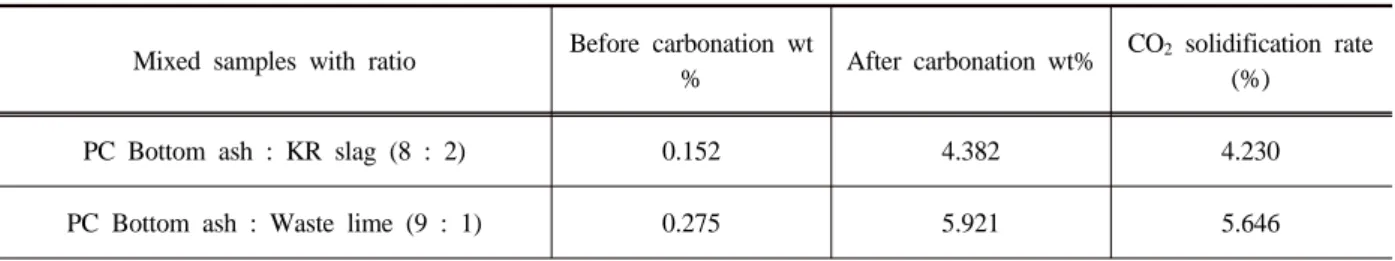
process, we used bottom ash mixed with KR slag (8:2 ratio) sample and bottom ash mixed with calcin- ed lime (9:1 ratio) samples. These two samples were used for carbonation process to stabilized heavy met- als and CO
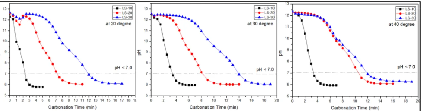
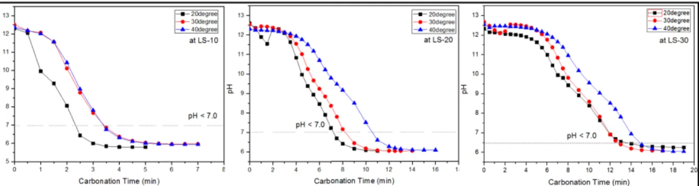
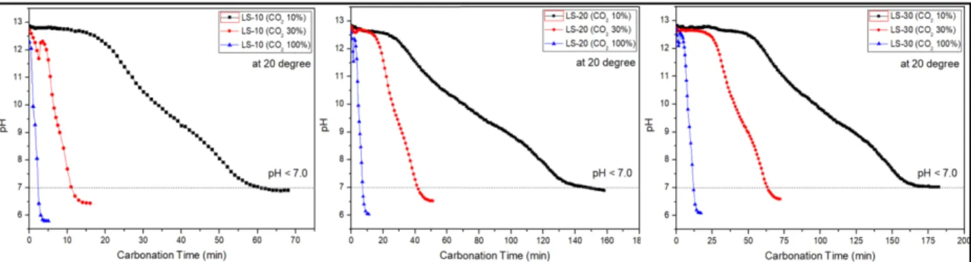
2sequestration process. The detailed ex- periment conditions were conducted with a liq- uid-solid ratio as 10-30 dm
3/kg, conducted with tem- perature as 20℃ to 40℃ and CO
2concentration as 10%, 30%, and 100%. Other conditions of the ex- periments used here were injection at a rate of 1L/min.
The experiment of carbonation was terminated when the measured pH was below 7 and did not change any further. Two phases are possible in bench scale carbonation process (a) liquid phase as a calcium ion (Ca
2+) source and (b) gas phase as carbonate ion (CO
32-) source. In a short time, the gas and the liq- uid mix together and form a turbulent flow for opti- mum mass transfer; finally, this process leads to the formation of calcite crystals.
2.2. Carbonation Process:
In this carbonation process, the CaO was hydrated
to form Ca(OH)
2slurry and is shifted to the carbo-
nation reactor chamber, the gaseous CO
2was in-
jected into the Ca(OH)
2slurry. The general mecha-
nism involved in the carbonation process can be ex-
pressed as follows:
Sample SiO
2Al
2O
3Fe
2O
3CaO MgO K
2O Na
2O TiO
2MnO P
2O
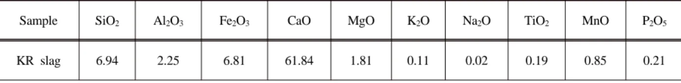
5KR slag 6.94 2.25 6.81 61.84 1.81 0.11 0.02 0.19 0.85 0.21
Table 2. KR (Kanvera Reactor) Slag XRF chemical analysis result (unit: wt %)
Sample SiO
2Al
2O
3Fe
2O
3CaO MgO K
2O Na
2O TiO
2MnO P
2O
5PC Bottom ash 57.75 21.29 8.74 4.31 1.34 1.07 0.72 0.13 0.09 0.31
Table 1. PC type power plant Bottom ash XRF Chemical analysis result (Unit: wt %)
CaO + H
2O → Ca(OH)
2(1)
Ca 2OH Ca(OH)
2Water
2
(2)
The dissociation of aqueous carbon dioxide,
H O CO 2H
CO
2(aq) 2 32(3)
These processes produce a fast supersaturating (S
I) of solution with respect to calcite,
K 1 ) )(CO S (Ca
sp 2 3 2
I