서론 1.
원자력발전소에서 시공되는 냉각수 취수관로는 주로 강재나 콘크리트로 제작하고 있으나 시간이 경과됨에 따라 수송유체 및 지하수 등에 의한 마모 나 부식으로 관의 내구성이 저하되어 구조적 안전 성이 결여되고 부분적인 파손의 위험뿐만 아니라 관의 수명이 단축되는 경우가 빈번하게 발생하고 있다 특히 콘크리트 관은 재료의 취성으로 인해 . , 상재하중 및 과도한 진동 등에 의한 균열이 발생하 고 중성화 보강철근의 부식 등 내구성의 감소로 지 ,
속적인 유지관리가 필요하다 이러한 지중매설관의 . 문제점을 해결하기 위해 유리섬유강화플라스틱 (Glass fiber reinforced polymer plastic, GRP) 재질로 구성된 관을 적용하였다.
관은 타관종
GRP 과 비교할 때 재료 자체의 우수 한 강성과 강도를 가지고 있으며 타관종과의 호환 , 성 등이 우수하여 지중에 매설할 경우 하부 지반지 지력 부족으로 인한 침하감소 침하에 따른 재료의 , 파손 위험성을 감소시킬 수 있는 등 다양한 장점을 가지고 있다.
관과 같은 연성관은 도관이나 콘크리트 관 GRP
과 같은 강성관과는 달리 구조적 거동 및 설계방법 DOI http://dx.doi.org/10.11004/kosacs.2013.4.3.038
지중매설 GRP 관의 관변형 예측
김선희
1· 이영근
1· 주형중
2· 정남진
3· 윤순종
4홍익대학교 토목공학과 박사과정
1, ㈜ 아이시스이엔씨 대표이사
2, 세진특허법률사무소 변리사
3, 홍익대학교
토목공학과 교수
4Prediction of Ring Deflection GRP Pipe Buried Underground
Kim, Sun-Hee
1· Lee, Young-Geun
1· Joo, Hyung-Jung
3· Jung, Nam-Jin
4· Yoon, Soon-Jong
51
PhD. Student, Department of Civil Engineering, Hongik University, Seoul, Korea
2
A Representative Director, ISIS E&C, 461-25, Seogyo-dong, Mapo-gu, Seoul, Korea
3
A Patent Attorney, International Patent & Trademark Office, 637-20 Yeoksam 1-dong, Gangnam-gu, Seoul, Korea
4
Professor, Department of Civil Engineering, Hongik University, Seoul, Korea
A bstract: Glass fiber reinforced plastic (GRP) pipes buried underground are attractive for use in harsh environments, such as for the collection and transmission of liquids which are abrasive and/or corrosive. I n this paper, we present the result of investigation pertaining to the structural behavior of GRP flexible pipes buried underground. In the investigation of structural behavior such as a ring deflection, experimental and analytical studies are conducted. In addition, vertical ring deflection is measured by the field test and finite element analysis (FEA) is also conducted to simulate behavior of GRP pipe buried underground. Based on the results from the finite element analyses considering soil-pipe interaction the vertical ring deflection behavior of buried GRP pipe is predicted. In addition, analytical and experimental results are compared and discussed.
Key Words: GRP pipe, Field test, Finite element analysis (FEA), Vertical ring deflection
주요어: GRP 관 현장매설실험 유한요소해석 관변형 , , , Corresponding author: Yoon, Soon-Jong
Department of Civil Engineering, Hongik University, 72-1 Sangsu-dong, Mapo-gu, Seoul 172-732, Korea.
Tel: +82-2-3141-0774, Fax: +82-2-3141-0774, E-mail: [email protected]
투고일 : 2013 년 월 8 14 일 / 수정일 : 2013 년 월 일 9 1 / 게재확정일 : 2013 년 월 9 23 일
에서 지반과의 상호작용을 검토해야 하기 때문에 현장적용을 위해서 다양한 측면의 검토가 선행되어 야 한다.
의 역학적 성질은 구성재료의 종류와 보강섬 FRP
유의 배치방향에 따라 역학적 성질이 크게 차이나 기 때문에 GRP 관의 제작방법에 따라 역학적 성질 을 조사하여야 한다 이 연구에서 사용한 . GRP 관 시편은 내경이 2,400 mm 이며 현장매설시 관변형을 , 예측하기 위해 원강성시험을 수행하였고 현장매설 , 실험은 기존연구자료 (Research Report, 2011) 와 같은 방법으로 수행하였다 또한 . , Iowa 설계식에 의한 결과와 수치해석을 통한 연구결과를 비교하였 고 현장매설실험을 수행하여 지중매설 , GRP 관의 구조적 신뢰성을 검토하였다.
역학적 성질 2.
관의 특성 2.1 GRP
관은 원주방향으로 연속섬유를 사용하기 때 GRP
문에 원주방향의 강성과 강도가 우수하다 . GRP 관 은 표면이 유리처럼 매끄러워 다른 종류의 관보다 더 많은 유체를 이송할 수 있는 장점을 가지고 있 다 . 기존에 ㈜ 한국화이바에서 제작된 GRP 관은 내 폴리에스터 수지를 사용하였으며 보강섬유
GRP ,
는 연속 유리섬유를 사용하고 중간층에 모래와 폴 리에스터 수지를 주재료로 한 레진모르타르가 배치 되는 형태 (Kim, 2011) 였으나 이 연구에서 적용한 , 관은 한국화이바에서 필라멘트와인딩 공정
GRP ㈜
에 의해 생산된 것으로서 중간 레진모르타르층 없 이 전단면이 FRP 로 구성된 관 (Reinforced 으로 보강섬유는 Thermosetting Resin Pipe, RTRP)
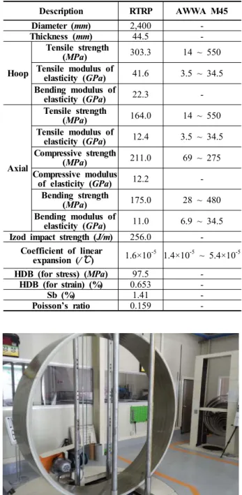
유리섬유 수지는 비닐에스터로 제작하여 화학적 저항 , 성을 보완하였다 . Table 1 은 GRP 관의 물리적 성질 및 역학적 성질을 나타내었다.
관의 구조적 거동 2.2 GRP
관의 역학적 성질을 조사하기 위하여
GRP GRP
관의 원강성시험은 KS M ISO 10466(2004) 을 참 고 하여 수행하였다 시험에 사용된 시편은 내경 g . 2,400 mm , 두께 44.5 mm , 폭 480 mm 로 제작하였 다 . GRP 관의 원강성시험은 Fig. 1 에 나타낸 것과 같이 ㈜ 한국하이바 실험실에 있는 100 kN 용량의 원강성시험기를 이용하여 하중을 재하하였으며 하 , 중은 변위제어방식으로 12.5 mm / min 의 속도로 재 하하였다 시편에 재하된 하중과 변위는 컴퓨터로 . 자동 전달 기록 저장되도록 하였으며 시험결과는 , , ,
에 정리하였다
Table 2 .
Table 1. Characteristics of GRP Pipe (Research Report, 2013)
Description RTRP AWWA M45
Diameter (mm) 2,400 -
Thickness (mm) 44.5 -
Hoop
Tensile strength
(MPa) 303.3 14 ~ 550
Tensile modulus of
elasticity (GPa) 41.6 3.5 ~ 34.5 Bending modulus of
elasticity (GPa) 22.3 -
Axial
Tensile strength
(MPa) 164.0 14 ~ 550
Tensile modulus of
elasticity (GPa) 12.4 3.5 ~ 34.5 Compressive strength
(MPa) 211.0 69 ~ 275
Compressive modulus
of elasticity (GPa) 12.2 - Bending strength
(MPa) 175.0 28 ~ 480
Bending modulus of
elasticity (GPa) 11.0 6.9 ~ 34.5 Izod impact strength (J/m) 256.0 -
Coefficient of linear
expansion (/ ℃ ) 1.6×10
-51.4×10
-5~ 5.4×10
-5HDB (for stress) (MPa) 97.5 -
HDB (for strain) (%) 0.653 -
Sb (%) 1.41 -
Poisson’s ratio 0.159 -
Fig. 1 Parallel Plate Loading Test Set-up (KS M ISO 10466)
Table 2. Result of the Parallel Plate Loading Test of GRP Pipes (Research Report, 2013)
At 5% ring deflection At failure load (kN/m)
Modulus of elasticity
(GPa) Load
(kN/m)
PS (kN/m
2)
74.35 619.56 1,765.88 23.00
지중매설 관의 설계
3. GRP
지중매설관은 구조적 거동에 따라 강성관과 연성 관으로 구분된다 연성관으로 분류되는 GRP 관은 지중에 매설할 경우 식 과 같이 관변형을 예측하 여 설계하도록 제안하고 있다(Watkins, 2000; Kim, et al., 2012; AWWA, 2005; ASTM D 2412, 2011)
′
여기서, ∆ : 수평방향 변형
: 변형지연계수
′ : 지반반력계수
: 관 강성
: 연직토압
식 (1) 은 지중매설된 연성관의 변형을 예측하는 식으로 연성관의 강성 되메움 흙의 지반반력계수 , , 기초조건 등 지중매설상태에서 연성관의 거동을 명 확히 표현하고 있다 식 . (1) 은 ASTM D 2412
에서도 제안하고 있으며 에 의해
(2011) Spangler
최초로 제안되었다 이 식은 . Iowa Formula 라고 하 며 파형강관에 대한 실험적 연구로 관변형이 약 , 에서 파괴될 때 안전율 를 적용하여 허용관변
20% 4
형을 5% 이내로 제한하고 있다 (Watkins, 2000).
현장매설실험 4.
원자력발전소의 냉각수 취수관로 대체 관종으로 검토중인 GRP 관의 구조적 거동을 분석하기 위해 관을 매설하고 매설 위치에 토사를 성토하여 GRP
시공과정 및 시공후의 관변형을 계측하는 현장매설 실험을 실시하였다.
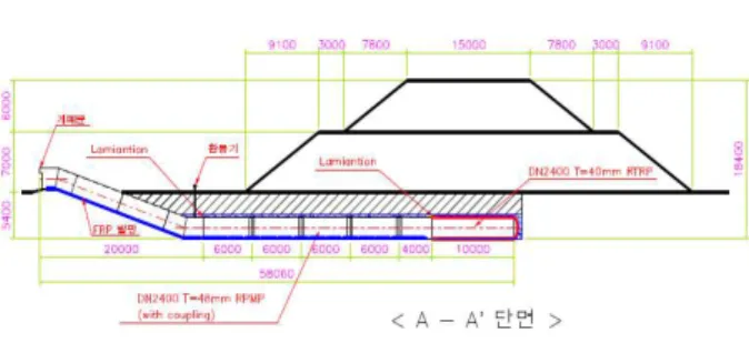
현장매설실험에 사용된 GRP 관은 내경이 2,400 mm 를 사용하였으며 관매설 측면도는 , Fig. 2 에 나타내었다 . GRP 관을 매설하고 관상부에 되메움토를 16 m 성토하여 시공하였으며 시공단계부터 관변형을 측정하였다.
설계에 고려된 GRP 관은 관 길이방향으로 동일 한 하중이 작용할 수 있도록 성토사면 중앙에 설치 하였으며, 6 m 길이의 관 4 개와 4 m 길이의 관 개 1 를 계측을 위한 진입로로 연결하여 길이방향으로 총 58 m 를 시공하였다 . Fig. 3 은 현장에 매설한
관의 시험시공 전경이다
GRP .
Fig. 2 Side View of GRP Pipe Underground (Research Report, 2013)
(a) Excavation
(b) Bedding
(c) Connection and Installation
(e) First Layer Backfill
(f) Second Layer Backfill and Completion
Fig. 3 Installation of GRP Pipe Buried Underground (Research Report, 2013)
지중매설 GRP 관은 주변 토사의 특성에 의한 영 향이 비교적 크기 때문에 되메움 흙의 다짐상태에 대한 들밀도시험 및 되메움 흙의 입도분석시험을 하였다 지중매설 . GRP 관의 상부 되메우기는 관 상단 300 mm 부터 300 mm 씩 3 개의 층으로 다짐을 하였다 들밀도시험결과 관 상단부의 습윤단위밀도 . 는 2.096
로 냉각수 취수관로를 설치하기 위한 요구조건(2.003
) 에 적합하였다 또한 . , 다짐도는 관 기초부 97.05%, 관 상단부 97.64% 로 모두 97% 를 초과하였으며 , AWWA M 45 (2005) 에서 제시하고 있는 양호한 다짐상태 (90% 이상 이 )
다.
지중매설된 GRP 관의 관변형 측정은 총 개소에 3 서 수직방향과 수평방향을 측정하였다 계측기 설치 . 위치는 Fig. 4 와 같으며 설치 위치는 관단부의 구 속효과가 영향을 미치지 않는 관 중앙부(No. 1), 관 강성이 변화될 수 있는 관 연결부 (No. 3), 관 중앙부와 연결부의 중간 (No. 2) 에 Dial Gage 를 사 용하여 설치하였다.
10.0m
5.0m 7.5m
No. 1 No. 2 No. 3
RPMP 접속부
Fig. 4 Location of Measurement (Research Report, 2013)
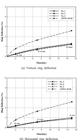
관변형 측정은 관을 설치한 후부터 시공단계 및 16 m 성토 후 지속적으로 수행하였다 각 계측기로 . 부터 측정한 수직 및 수평 방향 관변형을 Fig. 5 에 나타내었다.
(a) Vertical ring deflection (%)
(b) Horizontal ring deflection (%)
Fig. 5 Result of Ring Deflection (Research Report, 2013)
(d) Backfill
유한요소해석 4.
지중매설 GRP 관의 거동을 분석하고 현장계측결 과와 비교하기 위해 3 차원 수치해석을 매설심도에 따라 수행하였다 수치해석에 사용된 프로그램은 지 . 반공학분야에서 널리 쓰이는 FLAC 3D 이다 . GRP 관 상부에 5, 10, 16 m 매설심도에 따라 각각 모델 링을 하였다 해석에 사용한 지반특성치는 . Table 3 과 같이 관 주변 기초에 대해서 다짐상태를 반영하 였다 또한 해석에 사용한 . , GRP 관의 역학적 성질 은 Table 4 에 정리하였다 .
Table 3. Pipe Bedding and Backfill Material (PBM) Characteristics (Research Report, 2013)
Description PBM #1 PBM #2
Soil modulus,
(kN/m2) 30,000 3,000
Poisson’s ratio, υ 0.30 0.30
Unit weight,
ν
t(kN/m
3) 17.85 17.85
Viscosity,
(kN/m
2) 0.0 0.0
Internal friction angle, () 30.0 30.0
Compaction Well Poor
Table 4. Mechanical Properties of GRP Pipe (Research Report, 2013)
Description
Modulus of elasticity E (GPa)
Poisson’s ratio
ν
Thickness t (mm)
GRP pipe 23.00 0.16 44
수치해석은 GRP 관 주변 지반의 다짐상태에 따 라 Table 5 와 같이 가지 3 Case 로 구분하여 해석을 각각 수행하였다 수치해석결과 토피고에 따라 지반 . 에 발생하는 변위의 분포는 Table 5 와 같은 해석 조건에 따라 나타내었으며 GRP 관에 발생하는 변 위 분포는 Fig. 6 과 같다 또한 해석조건별 수치해 . , 석결과는 Table 6 과 같다 .
Table 5. Soil Conditions around the GRP Pipe (Research Report, 2013)
Description Soil condition around GRP pipe Domain Soil characteristic Case 1 Whole of soil
around GRP pipe
Pipe bedding material #1 Case 2 Center of GRP
pipe (2×D)
Pipe bedding material #2 Case 3 Center of GRP
pipe (3×D)
Pipe bedding material #2
(a) Vertical deflection (5m) (d) Horizontal deflection (5m)
(b) Vertical deflection (10m) (e) Horizontal deflection (10m)
(c) Vertical deflection (16m) (f) Horizontal deflection (16m) Fig. 6 Result of Ring Deflection (Research Report, 2013)
Table 6. Results of Analytical Study (Research Report, 2013)
Desc -ripti on
Burie d depth
(m)
Finite element analysis (mm)
Total Vertica
l ring deflect
ion (mm)
Total Horizont
al ring deflectio
n (mm) Poin
t A Poin
t B Poin
t C Point
D
Case 1
5 11.52 -1.85 -1.85 -7.75 3.78 -3.69
10 27.51 -3.98 -3.98 -19.38 8.13 -7.96
16 47.18 -6.60 -6.60 -33.65 13.5 -13.2
Case 2
5 19.45 -3.65 -3.65 -11.71 7.74 -7.30
10 37.94 -6.54 -6.55 -23.99 13.9 -13.1
16 60.22 -9.95 -9.96 -38.94 21.3 -19.9
Case 3
5 27.13 -5.95 -5.95 -14.90 12.2 -11.9
10 49.66 -10.6 6
-10.6
6 -27.69 22.0 -21.3
16 75.79 -15.9 8
-15.9
8 -42.82 33.0 -32.0
결론 6.
수직방향 관변형은 관 연결부 (No. 3), 수평방향 관변형은 관 중앙부와 관연결부의 중간부 (No. 2) 에 서 가장 크게 발생하였다 수평변위는 . No. 2 에서 가장 큰 변위가 발생하였으나 No. 3 과 불과 0.09 mm 의 차이를 나타내고 있기 때문에 계측상의 오차를 감안했을 때 동일한 정도의 변위라고 생각 된다 지중매설시험 결과 수직 및 수평 방향 관변형 . 과 수치해석 결과를 비교하여 Table 7 과 Fig. 7 에 나타내었다.
Table 7. Comparison of Results (Research Report, 2013)
현장매설실험 결과 수직 및 수평 방향 관변형과 설계식에 적용한 결과를 비교하여 과
Iowa Table 8
에 나타내었다 실험결과 토피고가
Fig. 8 . 16 m 일 경
우 시공완료 시점에 현장에서 측정한 수직방향 관 변형은 Iowa 설계식에서 제안하고 있는 관변형 예 측값보다 48% 작게 나타났으며 수평방향 관변형 , 은 35% 크게 나타났다 수평방향과 수직방향의 최 . 대관변형의 차이는 약 8 mm 로 내경이 2,400 mm 인 관경을 고려할 때 지반특성 등 설계변수의 측정오 차를 고려하면 매우 작은 차이이다 따라서 . , GRP 관변형은 현장매설실험을 하지 않고도 관변형식과 유한요소해석으로 예측가능함을 확인하였다.
Table 8. Comparison of Experimental Ring Deflection (Research Report, 2013)
Buried depth (m) 5 10 16
Finite element analysis (mm)
Case 1
Vertical
ring deflection 3.78 8.13 13.5 Horizontal
ring deflection -3.69 -7.96 -13.2
Case 2
Vertical
ring deflection 7.74 13.9 21.3 Horizontal
ring deflection -7.30 -13.1 -19.9
Case 3
Vertical
ring deflection 12.2 22.0 33.0 Horizontal
ring deflection -11.9 -21.3 -32.0
Experimental ring deflection
Vertical
ring deflection 6.00 18 28.84 Horizontal
ring deflection 3.76 13.17 20.84 (+): increase of diameter, (-): decrease of diameter
0 5 10 15 20 25 30
0 1 2 3 4
Stage Number CASE 1
CASE 2 CASE 3 Test
(a) Case by analytical vertical ring deflection
0 5 1 0 1 5 2 0 2 5 3 0 3 5
0 1 2 3 4
Stage Nu mber Horizontal Deformation (mm) . CASE 1
CASE 2 CASE 3 Tes t