• 검색 결과가 없습니다.

Multi-support excitation shaking table test of a base-isolated steel cable-stayed bridge

N/A
N/A
Protected

Academic year: 2021

Share "Multi-support excitation shaking table test of a base-isolated steel cable-stayed bridge"

Copied!
11
0
0

로드 중.... (전체 텍스트 보기)

전체 글

(1)

2015년 7월 http://dx.doi.org/10.5000/EESK.2015.19.4.161

지진격리 강재 케이블 교량의 다지점 진동대 실험

Multi-support excitation shaking table test of a base-isolated steel cable-stayed bridge

김성도1) ・ 안진희2) ・ 공영이3) ・ 최형석3) ・ 정진환3)*

Kim, Seong-Do1)* ・ Ahn, Jin-Hee2) ・ Kong, Young-Ee3) ・ Choi, Hyoung-Suk3) ・ Cheung, Jin-Hwan3)*

1)경성대학교 토목공학과, 2)경남과학기술대학교, 토목공학과, 3)부산대학교, 사회환경시스템공학과

1)School of Civil, Urban, and Environmental Engineering, Kyungsung University 2)Department of Civil Engineering, Gyeongnam National University of Science and Technology 3)Department of Civil and Environmental Engineering, Pusan National University.

/ A B S T R A C T /

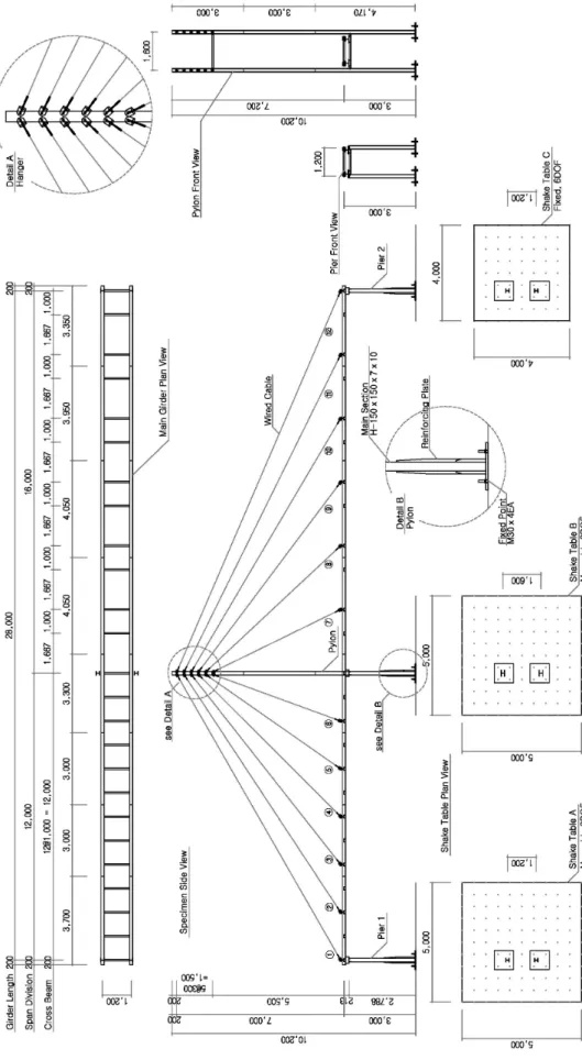
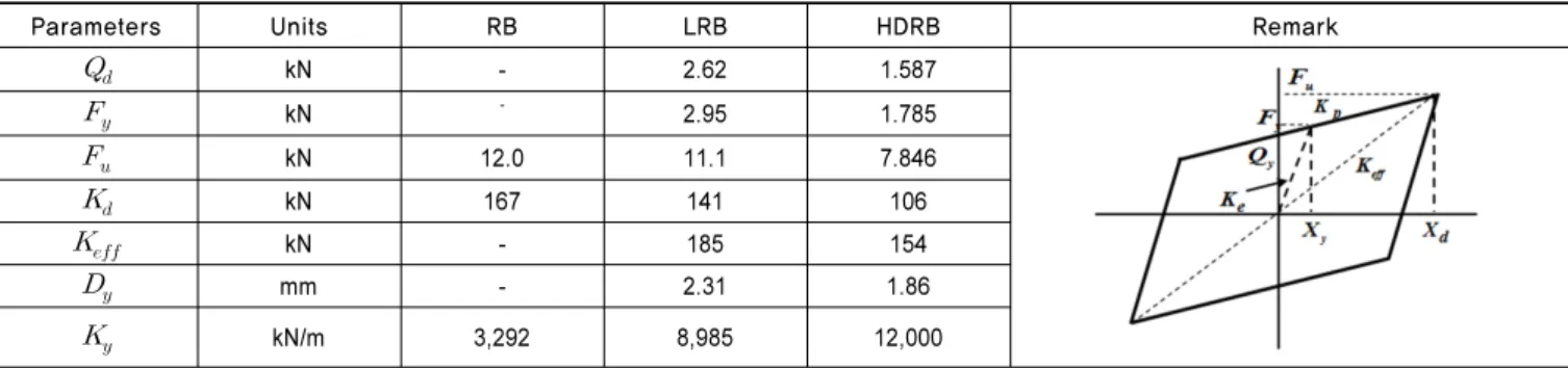
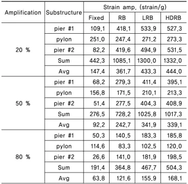
A series of tests was conducted for full-scale single-pylon asymmetric cable-stayed bridges using a system of multiple shaking tables. The 2-span bridge length was 28 m, and the pylon height was 10.2 m. 4 different base conditions were considered: the fixed condition, RB (rubber bearings), LRB (lead rubber bearings), and HDRB (high damping rubber bearings). Based on investigation of the seismic response, the accelerations and displacements in the axial direction of the isolated bridge were increased compared to non-isolated case.

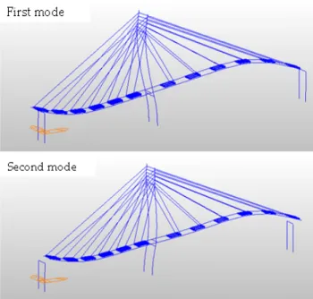
However, the strain of the pylon was decreased, because the major mode of the structure was changed to translation for the axial direction due to the dynamic mass. The response of the cable bridge could differ from the desired response according to the locations and characteristics of the seismic isolator. Therefore, caution is required in the design and prediction in regard to the location and behavior of the seismic isolator.

Key words: Steel cable-stayed bridge, Multi-support excitation shaking table, Dynamic response, Base-isolation condition.

*Corresponding author: Cheung, Jin-Hwan E-mail: [email protected]

(Received March 9, 2015; Revised May 19, 2015; Accepted May 21, 2015)

1. Introduction

Cable-stayed bridges have become very popular for their long span, structural efficiency, economical construction, and aesthetic advantages.

However, they can be susceptible to large-amplitude vibration under seismic, wind, traffic, and rain loadings because of their structural flexibility, low mass, and low damping (less than 5% critical damping) [1]. Base-isolation techniques using isolation bearings are generally used in continuous girder bridges, and they have been considered for cable-stayed bridges to reduce the large deck displacement and base shear of the towers [2].

Various studies have numerically investigated the effectiveness of base isolation for bridges [3, 4]. However, there has been no experimental research for seismically isolated cable-stayed bridge system. The shaking table test is well known as the most useful and effective

method to examine the seismic and dynamic behaviors of structural model fabricated based on the similitude law. Only a few experimental studies have been carried out for the cable bridges, and they used small-scale models without isolation bearings[5-7]. The space and payload limitation of shake table test systems and severe similitude requirements for dynamic testing significantly increase the difficulty [8]. Therefore, numerical analysis methods have mainly been used to evaluate seismic behaviors.

Multiple-shake-table systems have become a great approach to

examine full-scale multi-span bridges dynamically with the advance of

hydraulic actuators. Shoji et al.[9] examined the seismic response of a

PC cable-stayed bridge using a 1:100 scale model with long-period

ground motion. Yang et al.[10] examined the effect of wave

propagation on the seismic response of cable-stayed bridges using a

1:120 scale model and multiple shake tables. Zong et al.[11] also

conducted shaking table tests for a multi-span cable-stayed bridge

under multi-support excitations using a 1:100 scale model of a

three-tower bridge under uniform and non-uniform excitation. In these

(2)

Fig. 1. Shaking table system of SESTEC

Table 1. Specifications of multiple shake table system

Shaking table Size

(m) DOF Max. Payload (kg)

Max.

Acceleration (g)

Max.

Displacement (mm)

Max.

Velocity (mm/s)

Overturning Moment

(kN-m)

Operating Frequency

(Hz)

Table A 5 × 5 6 30,000 1.0 ± 300 1.00 2,000 0.1 ~ 60

Table B 5 × 5 3 60,000 1.0 ± 300 1.25 2,000 0.1 ~ 60

Table C 4 × 4 3 30,000 1.2 ± 300 1.50 1,200 0.1 ~ 60

tests, small-scale cable-stayed bridge models without isolation bearing were used to examine the seismic behavior and response under seismic excitations. Generally, it is difficult to make small size isolation bearings for the scaled model with good performance. Therefore, seismic tests using relatively large size model can be valuable for explaining the dynamic behaviors or the responses of seismically isolated cable-stayed bridge.

In this test, an relatively large size model of an asymmetrical cable-stayed bridge with isolation bearings was constructed on multiple shake tables, and the seismic responses for the isolation bridges were evaluated. A single-pylon asymmetric steel cable-stayed bridge with 28-m length and a 10.2-m-high pylon was fabricated on the 3 shake tables.

The dynamic characteristic response of the cable-stayed bridge was identified and compared according to the base-isolation conditions. 4 different base conditions were considered: the fixed condition at pylon, RB (rubber bearings), LRB (lead rubber bearings), and HDRB (high damping rubber bearings).

2. Seismic test conditions

For the asymmetrical cable-stayed bridge model, Midas Civil 2012 which is a commercial finite element analysis software was used to design the bridge and compare its basic structural responses. The relationship of the dynamic behaviors between the test bridge model and the numerical model was examined based on the results of testing and analysis.

2.1 Multiple-support shaking table system

A multi-support excitation shaking table system at SESTEC (Seismic Simulation Test Center, Pusan National University) was used for the seismic test as shown in Fig. 1. The system was consists of two moveable biaxial tables and one fixed 6 DOF table. This system is capable independent control and can run seismic tests using any combination of the three tables. The biaxial tables can be extended at intervals of up to 4 m and accommodate a 40-m-long bridge under non-uniform excitation. Table 1 shows the details of the system.

2.2 Cable-stayed bridge model 2.2.1 The bridge model design

Based on the test facility height and shake table locations, the pylon height of the bridge was determined as 10.2 m, and the total stayed length was 28 m (composed of 12-m and 16-m spans). The deck width consisting of two girders was 1.2 m. For fabrication, SM490 steel H-beams were used for the pylon and two pier members, and L and C-channels were used as the girders and cross beams. The slab was not considered for convenience of construction, but the slab mass was introduced using discrete steel mass blocks. The cables were made from 8 mm nominal-diameter wire rope made of IWRC grade B steel with an ultimate tensile strength of about 50 kN and elasticity modulus of 68 GPa. Each cable was tensioned by a swage stud and connected to the anchorage. Fig. 2 shows the dimensions of the designed cable-stayed bridge.

The fabrication involved seven processes: 1) assembling the

pylon, two piers, and two deck blocks, 2) installing cables on the upper

anchorages, 3) erecting the pylon and piers, 4) moving and combining

the deck blocks with cranes, 5) connecting and pre-stressing the cables

to the designed stress level and checking the pre-installed load values

simultaneously, 6) installing additional mass blocks onto the deck, and

7) installing sensors. Each part was connected by M16 bolts, and the

base of the pylon and piers were perfectly fixed onto each shaking table

with several M30 bolts. The support system allowed the bearing types

to be changed from general rollers and hinges to rubber bearings, lead

rubber bearings, and high damping bearings to determine the effect of

(3)

Fig. 2. Dimensions of a single-pylon asymmetric steel cable-stayed bridge

(4)

Fig. 3. Single-pylon asymmetric steel cable-stayed bridge model

Table 2. Design parameters of seismic isolators

Parameters Units RB LRB HDRB Remark

kN - 2.62 1.587

kN

-

2.95 1.785

kN 12.0 11.1 7.846

kN 167 141 106



kN - 185 154

mm - 2.31 1.86

kN/m 3,292 8,985 12,000

Table 3. Test program of a cable-stayed bridge

Test case Excitation Remarks

Random vibration test

White noise random

- Direction = Longitudinal direction - frequency = 0.5 Hz ~ 50 Hz - Amplitude = 0.10 g RMS

Natural frequency and mode shape check before and after the earthquake test

Earthquake motion test

El Centro earthquake (1940, NS component) - Direction = Longitudinal direction

- Amplification = 20, 50 and 80% of ZPA of El Centro Eq.

Fixed condition, RB, LRB, HDRB cases Fig. 4. Base-isolation condition of a cable-stayed bridge

the bearing system on the seismic response. Fig. 3 shows the single-pylon asymmetric steel cable-stayed bridge after installation on the multiple shaking tables.

2.2.2 Base-isolation conditions

To compare the dynamic response of a cable-stayed bridge, according to the base-isolation condition, the basement conditions of the bridge model were changed. The fixed basement condition at the pylon location and free to longitudinal direction at each pier was considered as reference case to examine the fundamental dynamic response for the purpose of comparison. The representative seismic isolated basements RB, LRB, and HDRB were applied at every support points. Table 2 shows the design parameters of each seismic isolated

basement, which were designed according to the dynamic behaviors of the bridge. Fig. 4 shows the applied base-isolated conditions of the tested cable-stayed bridge.

2.3 Seismic test program

The acceleration time history of the El Centro earthquake (1940, NS

component) was considered as the input motion for all of the test cases,

and the excitation level was gradually increased to its peak acceleration

(0.355 g). Random, white-noise tests were conducted to identify the

dynamic characteristics of the test bridge and to check the dynamic

response of the multiple shaking tables under dynamic loading conditions

before and after each seismic loading. Table 3 shows the summary of

the test program.

(5)

Fig. 5. Variable sensors and its locations

2.4 Instrumentation of a test cable-stayed bridge A total of 121 sensors were installed on the bridge to measure its

dynamic response. Fig. 5 shows the location of each sensor (accelerometers,

displacement transducers, load cells, and strain gages). Uniaxial load

cells with 20 kN capacity were attached between the swage stud and

(6)

(a) Acceleration table responses

(b) Displacement table response

(c) Acceleration response spectrum

Fig. 6. Shaking table responses for the 50% of El Centro Case upper cable anchorage to measure the cable forces. Strain gages were placed where the maximum stress could occur, like the bottom side of the pylon and piers. Tri-axial accelerometers were installed at the point of intersection of the deck and the pylon as a reference point. 12 biaxial and 6 uniaxial accelerometers were also attached to the cross beams to confirm the mode shapes, natural frequency, and other characteristics.

The data sampling rate was 512 Hz. At the same time, control feedback signals such as the displacement and acceleration in the longitudinal and lateral directions were also acquired for each shaking table with analog measurements.

3. Seismic test results

3.1 Multiple shaking table responses

The three shaking tables have several hydraulic actuators that are

controlled independently for the same seismic motion. To examine the seismic response of the bridge, the tables should have the same motion at the same time rather than multi-support excitation. To confirm that this was the case, the dynamic responses of each shaking table were compared using feedback signals from displacement transducers and accelerometers on each table.

Fig. 6 shows the acceleration over time, displacement relationship, and response spectrum of frequency and displacement for each shaking table under 50 % of El Centro earthquake conditions at the same time. The acceleration time history shown in Fig. 6 (a) reveals that the response of Table B was highest, since its seismic excitation was abnormal around 20 Hz band, as shown in Fig. 6 (b). This was occurred because the Table B supports the pylon, which supports most of the bridge load, and it has a high center of gravity and very flexible structural characteristics. The hydraulic actuator system of the shaking table was controlled by closed-loop control based on the response of the measured displacement and acceleration of the table. This control system is effective for seismic specimens with elastic-linear behaviors, but it is not effective for specimens with nonlinear behaviors.

However, it was difficult to find differences in the displacement responses and the response spectrums of each shaking table, since very small displacement is accompanied by around 20 Hz components.

Generally, the cable bridge system has very low frequency characteristics and this means that the seismic behaviors of the tested bridge were not affected much by excited high frequency around 20 Hz at Table B.

Therefore, it can be confirmed that the model bridge was tested under the uniform excitation conditions.

3.2 Natural frequency of the cable-stayed bridge

An FE model was introduced to analyze the bridge’s structural and dynamic behavior. The pylon, girders, and piers were modeled by general beam elements, and cables were modeled by truss elements considering pre-stress loading. The analysis results revealed the natural frequency and principal mode shapes. Fig. 7 shows the mode shape of the bridge calculated from the analysis. To identify the natural frequency of the cable-stayed bridge according to the base-isolation condition, white noise excitation with 0.1 g RMS (Root Mean Square) amplitude and 0.5 to 50.0 Hz frequency band was applied to the bridge model. The natural frequency was determined by calculating the transfer function from the response of each accelerometer installed on the pylon. Eq. 1 shows the transfer function ( 



):



   









(1)

where,  is the input acceleration component,  is the acceleration

(7)

Fig. 7. Mode shapes of the cable-stayed bridge model

Table 4. Natural frequency of the cable-stayed bridge

Mode No. Frequency (Hz)

Fixed RB LRB HDRB

1 1.25 1.56 1.61 1.22

2 1.66 - 1.81 1.97

(a) Fixed

(b) RB

(c) LRB

(d) HDRB

Fig. 8. Transfer function estimation result of El Centro response,  is frequency, 



is the cross-power spectral density of the

input and output signal, and 



is the power spectral density of the input and output signals. A symmetric Hamming window was used to exclude the noise component of the shaking table and the bridge.

Table 4 summarizes the transfer function estimation results of each base-isolation condition under random motion excitation. As shown, the natural frequencies of the bridge under the fixed condition were determined as 1.25 Hz (first mode; flexible mode of the pylon and girder) and 1.66 Hz (second mode; longitudinal translation mode). For the isolation conditions, the first and second mode frequencies were also evaluated similar to fixed condition because the input random motions intended to search the resonance prominence were not enough to excite the cable bridge model. Generally, the frequency characteristics of the isolated structure are mainly determined by the system mass and effective stiffness of the isolator but the first stiffness of the isolator was considered under random excitation.

In this study, therefore earthquake input motion was also used to measure the natural frequency of the bridge and to check the system changes according to the excitations. Fig. 8 shows the transfer function estimation results under the 50 % of El Centro earthquake excitation case for each base condition.

3.3 Dynamic responses of the bridge

Using the shaking table test results of the bridge, the measured

signals were evaluated to examine the effect on seismic responses of

the bridge depending on the input acceleration amplitude and basement

condition. To compare the seismic response for the base conditions,

(8)

(a) 20 % (b) 50 % (c) 80 % Fig. 9. Acceleration ratio of pylon height according depending on base-isolation conditions

(a) 20 % case

(b) 50 % case

(c) 80 % case

Fig. 10. Acceleration amplification of the girder each response signal was divided by RMS(Root Mean Square) values

of the Table B excitation feedback signals, because the table input motions were not exactly the same at every time to excite tables, even though the three controlled shake table motions could produce the same motion. Also, the measured signals have various noise components, such as cable vibrations, hinge sliding, and nut loosening.

Therefore, 5 Hz low-pass-filtered signals were used to compare the responses, which include the first and second modes of the bridge.

The seismic behaviors of the pylon were considered, since the pylon has longitudinal flexible behaviors that are affected by the first and second modes. Thus, the maximum acceleration of the pylon was compared, as shown in Fig. 9. In Fig. 9, the acceleration responses of the pylon increase in the order of HDRB, LRB, RB, and the fixed condition. Regardless of the seismic excitation amplitude, lower acceleration was measured in the upper part of the pylon, since deformation of the seismic isolator causes additional deformation and acceleration and a longer period.

The acceleration responses at pylon of the HDRB and LRB cases were similar with up to 50% seismic excitation amplitude, and they were higher than those of RB and the fixed condition. For the LRB and HDRB cases, higher acceleration in the longitudinal direction of the pylon was measured. This means higher deformations or displacements occurred considering the natural frequency of the bridge.

In the case of the vertical accelerations of the girder shown in Fig.

10, the seismic response of the girder with the isolator installed was lower than that in the fixed condition. This can be explained by the high amount of vertical behavior of the girder with increased seismic excitation, because the flexible behaviors of the pylon and girder are affected by the first mode. For cases with the seismic isolator installed, the vertical motion of the girder decreased, since the mass contribution of the first mode decreased according to the second mode of the

longitudinal motion.

For an isolator with hysteric behavior, the longitudinal motion is not

significant before the first stiffness yielding of the isolator. Thus, the

vertical behavior of the girder was similar to that of the fixed condition

(9)

(a) 20 % (b) 50 % (c) 80 % Fig. 11. Dynamic cable force vs. seismic acceleration depending on base-isolation condition

(a) Pier 1 on Table A

(b) Pylon

(c) Pier 2 on Table B

Fig. 12. Strain vs. seismic acceleration at substructure for the linear behavior of the isolator, and relatively small longitudinal

movement developed with 20% seismic excitation. Therefore, the seismic isolator is not effective for earthquakes that lead to relatively small displacements in the bearings.

Fig. 11 shows the dynamic forces of each cable depending on the base-isolation condition. For the 20% seismic excitation level, the dynamic cable force of the fixed condition case was highly changed.

For the 50% and 80% seismic excitation levels, the dynamic cable force of the RB case was high because of flexible deformation of the girder (first mode) with increased seismic excitation force. For LRB and HDRB with high mass contributions to the second mode, the dynamic force of each cable was not significantly changed.

Fig. 12 shows the strain of the pier and pylon depending on the base-isolation condition. The relative change of the measured strain at the pier and pylon decreased with increased seismic excitation force.

For the isolator-installed cases, the strain at the pylon and pier was higher than for the fixed condition case. For the fixed condition case, the strain was high at the pylon. However, the stress concentration on the pylon was relatively low from the measured strain ratio (strain at pylon/strain at pier), and higher strain at the pylon was measured in the isolator-installed case. This can be explained by the pylon sharing the seismic load with the deformed pier due to longitudinal shear force and moment, which occurred because appropriate longitudinal movement did not develop in the basement of the pier.

With roller supports, horizontal force and moments in the

longitudinal direction cannot be transferred to the substructure. In the

case of the basements used in the seismic loading test, however, the

horizontal force can be transferred to the pier from friction between the

connected plate of the basement device, and moments can also occur

through the length of the plate. Therefore, the behavior of the basement

should be considered in the design and fabrication of cable-stayed

(10)

Table 5. Substructure strain amplitude

Amplification Substructure Strain amp. (strain/g)

Fixed RB LRB HDRB

20 %

pier #1 109.1 418.1 533.9 527.3 pylon 251.0 247.4 271.2 273.3 pier #2 82.2 419.6 494.9 531.5 Sum 442.3 1085.1 1300.0 1332.0

Avg 147.4 361.7 433.3 444.0

50 %

pier #1 68.2 279.3 411.4 395.1 pylon 156.8 171.5 210.1 213.3 pier #2 51.4 277.5 404.3 408.9 Sum 276.5 728.2 1025.8 1017.3

Avg 92.2 242.7 341.9 339.1

80 %

pier #1 50.3 140.5 183.3 185.8

pylon 114.6 83.3 102.5 120.0

pier #2 26.6 141.0 181.9 198.5

Sum 191.4 364.8 467.7 504.3

Avg 63.8 121.6 155.9 168.1

bridges. Table 5 summarizes the measured substructure strains depending on the basement condition. As shown, the summation and average of strain at the substructure increased in the isolator-installed case, regardless of the seismic excitation level. This can be explained by the seismic force at the substructure being larger than that of the fixed condition (with a fixed condition at the pylon and a hinge condition at the pier).

Seismic isolators installed on a conventional continuous bridge share the horizontal force with the substructure and reduce the seismic load by changing the dynamic frequency of the bridge. This is suitable because of the high longitudinal stiffness of the slab in the continuous bridge and the high frequency of the bridge in the vertical direction.

However, in a cable-stayed bridge, the seismic load is transferred to the horizontal movement, and the vertical movement can be increased by the flexible behavior of the girder, because the cable-stayed bridge has relatively low longitudinal stiffness and flexible girders with low frequency. This may cause excessive stress in the pylon, which supports most of the load of the bridge. This behavior should be considered in the basement design of cable-stayed bridges.

4. Conclusions

An relatively large size cable-stayed bridge model which is not scaled by prototype with and without isolation bearings was designed and constructed on a multiple-shake-table system. From the test results, the following conclusions can be drawn:

1) The multiple-shake-table system was shown to be effective for the

large scale cable-stayed bridge model testing. Even though Table B (pylon location) was not controlled properly at high frequency range around 20 Hz, the frequency range is not significant to the main frequency of the bridge, and the difference in the controlled displacement was relatively small.

2) When the isolation bearing was installed at all of the bridge supports, the longitudinal accelerations at the top location of the pylon increased, the vertical acceleration of each center location of the girders was reduced, and the cable force decreased, since the mass participation of the first mode is decreased and longitudinal movement is dominant.

3) The measured strains corresponding to member forces were not reduced with the base-isolation condition in comparison to the fixed case because of the imperfections of the bridge design and construction. Therefore, the dynamic behavior and seismic performance of the isolation bearing should be carefully considered in the design and fabrication of cable-stayed bridges.

/ ACKNOWLEDGMENT /

This work was supported by a 2-Year Research Grant of Pusan National University

/ REFERENCES /

1. Ali HEM, Abdel-Ghaffar, AM. Seismic Passive Control of Cable-Stayed Bridges. Shock and Vibration. 1995;2(4):259–272.

2. Soneji BB, Jangid RS. Passive hybrid systems for earthquake protection of cable-stayed bridge. Engineering Structures. 2007;29(1):57–70.

3. Ali HEM, Abdel-Ghaffar AM. Seismic energy dissipation for cable- stayed bridges using passive devices. Earthquake Engineering and Structural Dynamics. 1994;23(8):877–893.

4. Soneji BB, Jangid RS. Effectiveness of seismic isolation for cable- stayed bridges. International Journal of Structural Stability and Dynamics. 2006;6(1):77–96.

5. Godden WG, Aslam M. Dynamic model studies of Ruck-A-Chucky Bridge. Journal of Structural Division. ASCE, 1978;104(12):1827-1844.

6. Garevski MA, Dumanoglu AA, Severn RT. Dynamic characteristics and seismic behavior of Jindo bridge South Korea, Structural Engineering Review. 1987;1, 141-149.

7. Wang J, Zhang XT, Fan LC, Wang ZQ, Chen H, Zhou M, Li S, Mo HL, Ni ZJ. A brief introduction to the shaking-table test of Liede Bridge. Proceedings 4th PRC-US Workshop on Seismic Analysis and Design of Special Bridges: Advancing Bridge Technologies in Research, Design, Construction and Preservation, Chongqing, China. c2006.

8. Yang CY, Cheung MMS. Shake Table Test of Cable-Stayed Bridge Subjected to Non-Uniform Excitation. Procedia Engineering.

2001;14:931–938.

(11)

9. Shoji G, Kogi T, Umesaka Y. Seismic response of a PC cable-stayed bridge subjected to a long-period ground motion. 14th WCEE.

Beijing, China, c2008.

10. Yang C, Cheung M, Xu X. Wave Propagation Effect on Seismic Response of Cable-stayed Bridge: A Multiple Shake Tables Test,

15th WCEE, Lisbon. c2012.

11. Zong Z, Zhou R, Huang X, Xia Z. Seismic response study on a

multi-span cable-stayed bridge scale model under multi-support

excitations. Part I: shaking table tests, Journal of Zhejiang University

SCIENCE A. 2008;15(5):351–363.

수치

Table 1.  Specifications of multiple shake table system
Fig. 2.  Dimensions of a single-pylon asymmetric steel cable-stayed bridge
Table 3.  Test program of a cable-stayed bridge
Fig. 5.  Variable sensors and its locations
+6

참조

관련 문서

The problem of atom migration can be solved by considering the thermodynamic condition for equilibrium; namely that the chemical potential of an atom must be the same

In this study, the 5th Korean Working Condition Survey conducted in 2017 was aimed at controlling the personal and occupational characteristics of workers to find out

Since every classical or virtual knot is equivalent to the unknot via a sequence of the extended Reidmeister moves together with the forbidden moves, illustrated in Section 2,

The life is determined as the time at which brightness of the lamp is 50% compared to that of initial value at the typical lamp current on condition of continuous

Moving from Traditional Payment Rails to Payment Networks 73 Fiat Currency Stablecoins Create More Interoperability between Ecosystems 74 Cryptocurrency and

The MC7800 Series of fixed voltage regulators are designed with Thermal Overload Protection that shuts down the circuit when subjected to an excessive power overload

1 John Owen, Justification by Faith Alone, in The Works of John Owen, ed. John Bolt, trans. Scott Clark, "Do This and Live: Christ's Active Obedience as the

Regarding SI or BI EMG measured at upright posture on hard platform, bio-feedback group under the condition with opening both eye and aqua group under the condition with