Ⅰ. Introduction
The International Commission of Radiation Units (ICRU) recommends that 95% of the prescription dose be distributed in clinical target volume (CTV), including systemic error, random error, and beam penumbra. In addition, planning target volume (PTV) includes CTV and the motions of internal margins for organs motion, include set-up margin for uncertainty of ready position and recommend be delivered sufficient
homogeneous dose[1,2].
The purpose of radiation therapy is to deliver the maximum radiation dose to the tumor and the minimize radiation dose to normal tissue. In the high energy radiation therapy, enough radiation dose cannot be delivered to target or PTV in the case of treatment of superficial tumor or diseases which need a surface dose because of the occurrence of the skin sparing effect. High energy radiation gives with D
maxat the specific depth according to percent depth dose (PDD).
<원저>
Manufacturing a Functional Bolus Using a 3D printer in Radiation Therapy
Yi-Seong Lee
1)・Jeong-Koo Kim
2)1)
Dept. of Radiation Oncology, Catholic Kwandong University International St. Mary’s Hospital
2)
Dept. of Radiological Science, Hanseo University
방사선치료에서 3D 프린터를 이용한 기능적 조직보상체의 제작
이이성
1)・김정구
2)1)가톨릭관동대학교 국제성모병원 방사선종양학과・2)한서대학교 방사선학과
Abstract
Commercial plate bolus is generally used for treatment of surface tumor and required surface dose. We fab- ricated 3D-printed bolus by using 3D printing technology and usability of 3D-printed bolus was evaluated. RT-structure of contoured plate bolus in the TPS was exported to DICOM files and converted to STL file by using converting program.
The 3D-printed bolus was manufactured with rubber-like translucent materials using a 3D printer. The dose distribution calculated in the TPS and compared the characteristics of the plate bolus and the 3D printed bolus. The absolute dose was measured inserting an ion chamber to the depth of 5 ㎝ and 10 ㎝ from the surface of the blue water phantom.
HU and ED were measured to compare the material characteristics. 100% dose was distributed at Dmax of 1.5 ㎝ below the surface when was applied without bolus. When the plate bolus and 3D-plate bolus were applied, dose distributed at 0.9 ㎝ and 0.8 ㎝ below the surface of the bolus. After the comparative analysis of the radiation dose at the reference depth, differences in radiation dose of 0.1 ~ 0.3% were found, but there was no difference dose. The usability of the 3D-printed bolus was thus confirmed and it is considered that the 3D-printed bolus can be applied in radiation therapy.
Key Words :
Bolus, Skin Sparing Effect, 3D Printing, Compensator, Skin Dose
중심 단어 :Bolus, 피부보호 효과, 3D 프린터, 조직보상체, 표면 선량
This research was supported by 2015 Hanseo University Research Program
Corresponding author: Jeong-Koo Kim, Department of Radiological Science, Hanseo University, 46, Hanseo1-ro, Haemi-myun, Seosan-si, Chungcheongnam-do, 31962, Republic of Korea / Tel: +82-41-660-1055 / E-mail: [email protected]
Received 15 January 2020; Revised 10 February 2020; Accepted 28 February 2020 Copyright ⓒ2020 by The Korean Journal of Radiological Science and Technology
The region between surfaces and D
maxis called a build-up region. The surface dose and skin dose deliver a much lower radiation dose than maximum radiation dose under the tissue because the build-up effects[3-5].
Because of the skin sparing effect of high-energy radiation, superficial tumors and treatments that require a skin dose need a bolus of tissue-equivalent material. The bolus increases the surface dose and decreases the skin sparing effect so that sufficient radiation can be delivered to tumors[6,7]. Types of boluses include water, wet cotton gauze, SuperFlab, petroleum-based, uncooked rice, paraffin wax, beeswax, Polyflex, Elasto-Gel, thermoplastic, Super-Flex, etc.
The usability of water boluses has been confirmed because muscle and fat tissue are equivalent material with water. However, there are limitations of practicality, reproducibility, and convenience in clinical.
In addition, plate boluses such as Superflab and Super-Flex, which are commonly used in radiation therapy, have limitations in the accuracy of the location, shape reproducibility, and maintaining form during the therapy period[8-10]. In recent years, 3D printing technology has been revolutionizing design, engineering, and manufacturing and is rapidly expanding into the medical industry. This technology has been transforming its applicability into the shapes of biomedical applications in medical research and operation simulation that can substitute tissues and organs[11-13]. In addition, many studies have been carried out on the production of compensator for the dose distribution equalization and the production of proton compensator using 3D printing technology in radiotherapy[14-17]. This study was purpose to evaluate the usability of a 3D-printed bolus that can substitute for the plate bolus that are commonly used to superficial tumor treatment and surface doses.
Ⅱ. Materials and Methods
1. Manufacturing the 3D-printed bolus
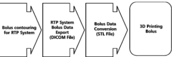
The blue water phantom (Standard Imaging, USA) images were acquired using a CT simulator (Somatom Definition AS, Siemens, Germany) at conditions of 120 kV, 35 mAs, 3 ㎜ slice thickness, and 1.0 pitch. The scanned images were registered in the radiation treatment planning system (TPS, MONACO Ver. 5.0, Elekta, USA) and then the CT images and RT-structures of contoured plate bolus were exported to Digital Imaging and Communications in Medicine (DICOM) files.
Converting DICOM file to stereolithography (STL) file is necessary to manufacture plate bolus using a 3D printer. The converted STL file(A-View, Prototech) was then entered into the 3D printer (Objet500 Connex3, Stratasys, USA), and the 3D-printed bolus was manufactured with rubber-like translucent materials (1,7,7-trimethylbicyclo[2.21] hept-2-yl acrylate) [Fig.
1, 2].
The scanned images were registered in the radiation treatment planning system and then CT images and RT-Structures of contoured plate-bolus were exported to DICOM files.
Fig 1. Schematic presentation of 3D Printing System
(a) (b)
Fig. 2. Schematic presentation of (a) plat-bolus,
(b) 3D printing bolus
2. Experimental Methods
To compare the characteristics of the plate and 3D-printed boluses, blue water phantom 1 ㎝ slices were stacked at a height of 20 ㎝ and images were acquired without applying the bolus. Images were acquired with 1 ㎝ thick plate bolus and 3D printing bolus, respectively. CT images were registered in the TPS, and then comparative analysis of the radiation dose distribution was performed by calculating the dose at conditions of 6 MV, 10 MV, 100 cGy, 0° Gantry 0°, Collimator, SSD 100 ㎝ , filed size 10 ㎝ × 10 ㎝, grid size 0.3 ㎝ for the Dmax. The absolute dose was measured to confirm the dose of the reference depth.
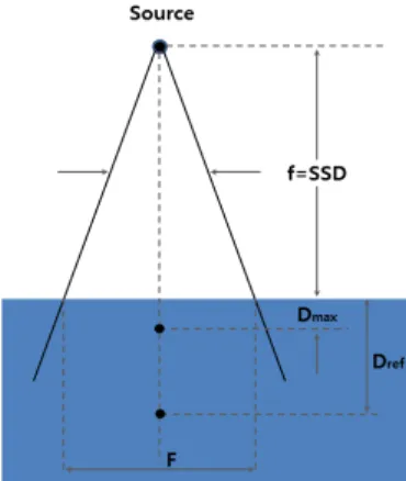
The respective absolute dose was measured inserting an ion chamber to the depth of 5 ㎝ and 10 ㎝ from the surface of the blue water phantom. Also, delivered 6 MV and 10 MV of 100 MU in conditions of Gantry 0°, Collimator 0°, SSD 100 ㎝, field size 10 ㎝ × 10 ㎝[Fig. 3].
Hounsfield units (HU) and electron density (ED) were measured to compare the material characteristics of the plate bolus and 3D-printed boluses with 0.8 ㎤ the volume of interest (VOI) setting in the TPS
Fig. 3.
Schematic diagram of absolute dose measurement Dmax : maximum dose, Dref : reference depthⅢ. Results
1. Analysis of the dose distribution
By TPS calculated doses at the same condition, dose distribution was measured at the blue water phantom
without bolus and with plate bolus and the 3D-printed bolus. 100% dose was distributed at Dmax of 1.5 ㎝ below the surface when was applied without bolus.
When the plate bolus was applied, 100% dose was distributed at 0.9 ㎝ below the surface of the bolus. And when the 3D printed bolus was applied, 100% dose was distributed at 0.8 ㎝ below the surface of the bolus.
95% dose was distributed at 3.0 ㎝ below the surface when was applied without bolus. When the plate bolus was applied, 95% dose was distributed at 3.64 ㎝ below the surface of the bolus. And when the 3D printed bolus was applied, 95% dose was distributed at 3.67 ㎝ below the surface of the bolus.
90% dose was distributed at 4.18 ㎝ below the surface when was applied without bolus. When the plate bolus was applied, 90% dose was distributed at 4.9 ㎝ below the surface of the bolus. And when the 3D printed bolus was applied, 90% dose was distributed at 4.92 ㎝ below the surface of the bolus<Table 1>, [Fig. 4].
2. Measuring of the absolute dose
Absolute dose was measured at the reference depth using a farmer-type ionization chamber. At the reference depth of 5 ㎝, 6 MV and 100 MU were measured. The absolute dose was measured 98.9 cGy when without bolus was applied, 100.4 cGy when a plate bolus was applied and 100.4 cGy when the 3D- printed bolus was applied. At the reference depth of 10 ㎝, 6 MV and 100 MU were measured. The absolute dose measured 97.1 cGy when without bolus was applied, 98.6 cGy when a plate bolus was applied and 98.3 cGy when the 3D-printed bolus was applied. At the reference depth of 5 ㎝, 10 MV and 100 MU were measured. The absolute dose was measured 98.4 cGy when without bolus was applied, 100.3 cGy when a plate bolus was applied and 100.3 cGy when the 3D-printed bolus was applied.
At the reference depth of 10 ㎝, 10 MV and 100 MU
were measured. The absolute dose was measured 97.4
cGy when without bolus was applied, 98.7 cGy when a
plate bolus was applied, and 98.4 cGy when the
3D-printed bolus was applied<Table 2>.
3. Comparing the characteristics of the bolus materials
The validity of the materials was investigated by comparing the material characteristics of the manufactured 3D-printed bolus, plate bolus, and blue
water phantom. HU and ED were measured in TPS by set up VOI. As result, average ED on the blue water phantom slide was 21 and the standard deviation was 34. The average ED on the blue water phantom slide was 1.030 and the standard deviation was 0.042. The
Table 1. Distance from D
maxto 100%, 95%, 90% isodose line (unit ㎝)
With out bolus With plate-bolus With 3D printing bolus100% 0.5 1.6 1.7
95% 1.5 1.14 1.17
90% 2.68 2.3 2.3
(a) (b) (c)
Fig. 4. Distributions of calculated dose (a) without bolus (b) with plate-bolus (c) with 3D printing plate-bolus. Isodose distribution of red line is 100% and orange line is 95%, yellow line is 90%, light green line is 80%, sky blue line is 60%, blue is 50%, navy blue line is 30%.
Table 2. Comparison of dose for blue water phantom at reference depth (unit cGy)
With out bolus With plate-bolus With 3D printing bolus6 MV 10 MV 6 MV 10 MV 6 MV 10 MV
5 ㎝ 98.9 98.4 100.4 100.3 100.2 100.3
10 ㎝ 97.1 97.4 98.6 98.7 98.3 98.4
(a) (b)