Ⅰ. 서 론
000 (small animal)
. CT, MRI, PET .
.
.
. ,
.
(molecular imaging) [1-3].
. GE Siemens
.
CT, MRI, (nuclear medicine)
. /
. , CT
, MRI ,
.
.
micro-CT, micro-PET, micro-MRI
. Micro-MRI MRI
. MRI
MRI
이수열
Developments of Small Animal Imaging Systems in Korea
Soo Yeol Lee
Dept. of Biomedical Engineering, Kyung Hee University (Received February 12, 2009. Accepted February 16, 2009)
Many types of small animal imaging modalities, like micro-CT, micro-PET, and micro-SPECT, have been recently developed worldwide.
Small animal imaging systems are now recognized as indispensable tools to validate efficacy and safety of new drugs or new therapeutic methods using the animal disease models. With increasing demands for small animal imaging in biomedical research, multimodal small animal imaging systems, like micro-PET/CT or micro PET/MRI, are now also being developed. Small animal imaging with spatial resolution and sensitivity comparable to human imaging is quite challenging since laboratory small animals are much smaller than human beings. Research activities in Korea on small animal imaging systems are reviewed in this paper. In the field of micro-CT and micro-PET, many world-class technologies have been developed successfully in Korea. It is expected that the developed animal imaging system technologies can be used in the development of clinical imaging systems in Korea in the near future.
micro-CT, micro-SPECT, micro-PET, small animal imaging
2
Corresponding Author : 이수열
경기도 용인시 기흥구 서천동 1 경희대학교 동서의료공학과 Tel : +82-31-201-2980 / Fax : +82-31-201-3666 E-mail : [email protected]
본 연구는 보건복지가족부 보건의료기술진흥사업(02-PJ3-PG6-EV07- 0002) 및 한국과학재단 우수연구센터사업(R11-2002-103)의 지원에 의하 여 이루어진 것임.
RF system
MRI micro-MRI
. CT, PET X-
.
micro-CT, micro-PET .
micro-PET/CT, micro-PET/MRI
(multi-modal imaging
system) [4].
.
.
3,000 .
10 .
.
micro-CT, micro-SPECT
micro-PET .
micro-CT, micro-PET
.
Ⅱ. Micro-CT의 개발
micro-CT 10μm×10μm×10μm
.
μm 2D .
CT mm x-
1D 2D
. CT 3
, (helical scanning) micro-CT
3
3 [5-11].
Micro-CT
. Micro-CT x-
x- . X-
x- s (penumbra)
.
(1)
ODD x- , SOD
x- . x-
, M=1+ODD/SOD
x- . x-
x- .
Micro-CT x x-
( ) x-
x- ( ) .
ODD
Rotating gantry X-ray source
Subject Couch
X-ray detector
LM actuator
Servo motor Sliding mechanism
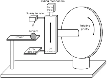
그림1. Zoom-in micro-CT의 개념도. 투영영상의 확대율을 x-선관과 x-선 디텍터를 이송하여 조절할 수 있다.
Fig. 1. A schematic diagram of the zoom-in micro-CT. The magnification ratio of the projection image can be controlled by moving the x-ray source and the x-ray detector.
.
. micro-CT
[5].
ODD
zoom-in micro-CT [12]. 1 zoom-in micro-CT x- x-
ODD SOD
.
. 2
[13]. 1-5
zoom-in
. x-
artifact .
CT
, CT
. local tomography
CT- . zoom-in
micro-CT CT-
. zoom-in .
Micro-CT 5-50μm micro-focus x-
. X- x-
.
x-
. X- x-
x- CT
. micro-CT
CT
. ex vivo in vivo
50μm .
Micro-CT 2D x-
. Micro-CT x- (image inten-
sifier) . x-
. micro-CT GdO2SO4
CsI(Tl) taper CCD
x- . taper
x-
micro-CT .
micro-CT 2D x- . 2D x-
. x-
.
. (amo-
rphous Si) CMOS [5].
CT ring artifact . Ring artifact
. x-
Sliding mechanism
Rotating gantry X-ray
detector
X-ray source Couch
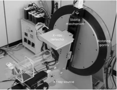
그림2. 경희대학교에서 개발한 zoom-in micro-CT.
Fig. 2. The zoom-in micro-CT developed at Kyung Hee University.
dead pixel
. micro-CT
. Micro-CT Feldkamp
[14]. filtered (back-projection)
. 2D high-pass
filtering 3
. 3
. PC 512×
512×512 3 100sec
. Feldkamp
. x- 10°
[14].
Micro-CT
. artifact retro-
spective [15]. 2 CT
micro-CT view
. ,
artifact .
. Micro-CT .
view x- 10ms
micro-focus x- x- .
0.3 mm x-
2 weeks 6 weeks 12 weeks
2 weeks 6 weeks 12 weeks
그림4. Micro-CT로 촬영한 정상 쥐의 대퇴골 영상(상) 및 골다공증 모델 쥐의 대퇴골 영상(하).
Fig. 4. Femur images of a control rat (top) and femur images of a rat with osteoporosis model (bottom) taken with the micro-CT.
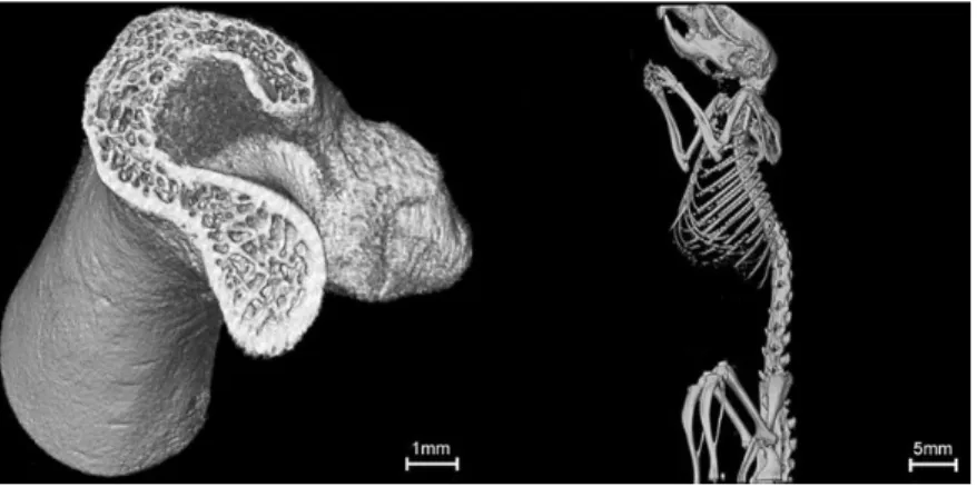
그림3. Micro-CT로 촬영한 쥐의 대퇴골 영상(좌) 및 전신 뼈 영상(우).
Fig. 3. A femur (left) and whole bone (right) images of a rat taken with the micro-CT.
CT .
micro-CT 250 x-
10ms .
100μm .
Micro-CT [16-20].
. micro-CT
(trabecular bone)
. 3 micro-CT
. 3mm
. .
[17]. 4
. Micro-CT
.
Micro-CT .
iodine .
. 10
. micro-CT [5].
Fenestra VC (ART Advanced Research Technologies Inc,
Canada) iodine
. . Fenestra LC
. micro-CT
. 5 Fenestra LC .
.
Ⅲ. Micro-SPECT의 개발
SPECT
. SPECT
(collimator) .
SPECT
. micro-SPECT
[21,22].
micro-SPECT
(pin hole) .
micro-SPECT .
10 .
.
1 mm 0.1%
[4].
SPECT CT
. SPECT CT
SPECT
그림5. 조영제 주입 후 Micro-CT로 촬영한 쥐의 복부 영상. Fig. 5. A contrast-enhanced abdomen image of a rat taken with the micro-CT.
CT SPECT/CT .
6 micro-SPECT [4].
Ⅳ. Micro-PET의 개발
PET SPECT ,
. (positron)
PET [4]. PET SPECT
.
(coincidence circuit) .
PET
. BGO LSO GSO
time window 4.5-6ns
400-450keV PET
[23].
(time-of-flight, TOF) .
.
500ps TOF
7.5cm [23]. mm PET
TOF
[23].
Micro-PET
, [4].
PET
2 ,
그림6. 소동물 촬영용 multi-pinhole SPECT/CT 시스템.
Fig. 6. Multi-pinhole SPECT/CT system for small animal imaging (MILABS, Utrecht, The Netherlands).
그림7. 삼성병원에서 개발한 소동물 촬영용 micro-PET 시스템. Fig. 7. The small animal PET system developed at Samsum Medical Center.
.
PET micro-PET
.
.
, LYSO/
LuYAP LYSO/GSO PET
[4]. PET
.
PET/CT ,
PET MRI PET/MRI
. PET/CT CT PET
PET
. CT
PET PET
. MRI CT
PET .
MRI CT
,
. MR
PET SPECT .
MRI PET MRI
PET/
MRI
. PET MRI
. MRI ppm
. PET MRI
MRI MRI
. MRI PET
. PET MRI
.
MRI
. PET MRI
. MRI 3
Tesla , MRI 10 Tesla
PET . MRI
PET
. PET/MRI PET
(Photomultiflier-tube, PMT)
PET/MRI .
PET .
MRI .
MRI PMT
[23].
PMT APD(Avalanche Photo Diode)
. APD 9.4 T
[24]. APD PMT
, PMT .
Hamamatsu R7600 PSPMT 400 nm
20% , S8550 APD
70% [4]. 7T
10cm LSO-APD 16
PET/MRI [*]. FOV 35cm×
12cm . PET/MRI
.
Siemens Medical Solutions APD APD
-PET .
APD PMT
. Silicon Photomultiplier (SiPM) APD
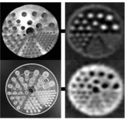
그림8. Micro-PET으로 촬영한 팬텀영상. 공간해상도는 1.3mm이다.
Fig. 8. Phantom images taken with the micro-PET system. The maximum spatial resolution is 1.3mm.
.
SiPM MRI PET
. ,
SiPM 3T MRI PET
PET [4].
SiPM LYSO 3T MRI
RF (Radio Frequency)
MRI SiPM
[4]. 7 micro-
PET , 8 9
.
1.3mm .
Ⅴ. 결 론
. Micro-CT, micro-PET . MRI, PET, CT
.
참고문헌
[1] M.G. Pomper, “Molecular imaging: an overview,” Acad. Radiol., vol. 8, pp. 1141-1153, 2001.
[2] R. Weissleder, and U. Mahmood, “Molecular imaging,” Radio- logy, vol. 219, pp. 316-333, 2001.
[3] T.F. Massoud, and S.S. Gambhir, “Molecular imaging in living subject: seeing fundamental biological processes in a new light,”
Genes & Development, vol. 17, pp. 545-580, 2003.
[4] J. H. Jung, Y. Choi, K.J. Hong, B.J. Min, W.H, and J.H. Kang,
“Recent advances in nuclear medicine imaging instrumentation,”
Nucl. Med. Mol. Imaging, vol. 42, pp.1-14, 2008.
[5] C.T. Badea, M. Drangova, D.W. Holdsworth, and G.A. Johnson,
“In vivo small-animal imaging using micro-CT and digital subtr- action angiography,” Phys. Med. Biol., vol. 53, pp. R319-R350, 2008.
[6] M.J. Paulus, H. Sari-Sarraf, S.S. Gleason, M. Bobrek, J.S. Hicks, D.K. Johnson, J.K. Behel, L.H. Thompson, and W.C. Allen, “A new x-ray computed tomography system for laboratory mouse imaging,” IEEE. Trans. Nucl. Sci., vol. 46, pp. 558-564, 1999.
[7] M.J. Paulus, S.S. Gleason, H. Sari-Sarraf, D.K. Johnson, C.J.
Foltz, D.W. Austin, M.E. Easterly, E.J. Michaud, M.S. Dhar, P.R.
Hunsicker, J.W. Wall, and M. Schell, “High-resolution x-ray CT screening of mutant mouse models,” in Proc. SPIE, San Jose, CA, USA, Jan, 2000, vol. 3291, pp. 270-279.
[8] S.Y. Wan, A.P. Kiraly, E.L. Ritman, and W.E. Higgins, “Extraction of the hepatic vasculature in rats using 3-D micro-CT images,”
IEEE. Trans. Med. Imag., vol. 19, pp. 964-971, 2000.
[9] E.L. Ritman, “Molecular imaging in small animals-roles for micro-CT,” J. Cell. Biochem. Supp., vol. 39, pp. 116-124, 2002.
[10] S.C. Lee, H.K. Kim, I.K. Chun, M.H. Cho, S.Y. Lee, and M.H.
Cho, “A flat-panel detector based micro-CT system: performance evaluation for small-animal imaging,” Phys. Med. Biol., vol. 48, pp. 4173-4185, 2003.
[11] D.A. Jaffray, and J.H. Siewerdsen, “Cone-beam computed tomography with a flat-panel imager: initial performance chara- cterization,” Med. Phys., vol. 27, pp. 1311-1123, 2000.
[12] I.K. Chun, M.H. Cho, S.C. Lee, M.H. Cho, and S.Y. Lee, “X-ray micro-tomography system for small-animal imaging with zoom- in imaging capability,” Phys. Med. Biol., vol. 49, pp. 3889-3902, 2004.
[13] M.H. Cho, D.H. Lee, B.H. Han, and S.Y. Lee, “Rotating-gantry- based x-ray micro-tomography system with the sliding mecha- nism capable of zoom-in imaging,” J. Biomed. Eng. Res., vol. 29, pp. 107-113, 2008.
[14] L.A. Feldkamp, L.C. Davis, and J.W. Kress, “Practical cone- beam algorithm,” J. Opt Soc. Am. A, vol. 1, pp. 612-619, 1984.
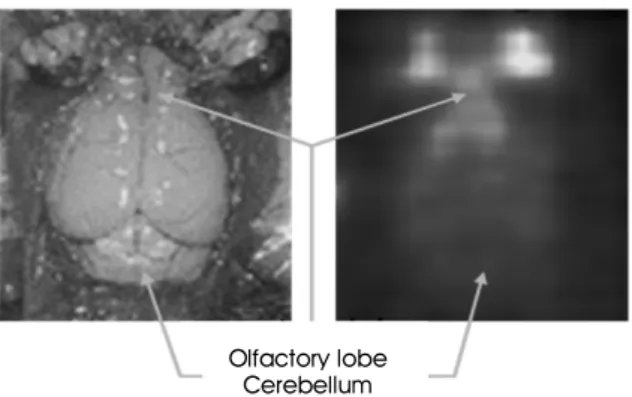
[15] C. Chavarrias, J.J. Vaquero, A. Sisniega, A. Rodriguez-Ruano, Olfactory lobe
Cerebellum
그림9. 쥐 뇌의 광학영상(좌) 및 micro-PET 영상(우).
Fig. 9. An optical image (left) and a PET image (right) of a rat brain.
M.L. Soto-Montenegro, P. Garcia-Barreno, and M. Desco,
“Extraction of the respiratory signal from small-animal CT projections for a retrospective gating method,” Phys. Med. Biol., vol. 53, pp. 4683-4695, 2008.
[16] R.D. Kapadia, G.B. Stroup, A.M. Badger, B. Koller, J.M. Levin, R.W. Coatney, R.A. Dodds, X. Liang, M.W. Lark, and M.
Gowen,” Application of micro-CT and MR microscopy to study pre-clinical models of osteoporosis and osteoarthritis,” Technol.
Health Care, vol. 6, pp. 361-372, 1998.
[17] I.K. Chun, M.H. Cho, J.H. Park, and S.Y. Lee, “In vivo trabecular thickness measurement in cancellous bones: longitudinal rat imaging studies,” Physio. Meas., vol. 27, pp. 695-702, 2006.
[18] S.M. Jorgensen, O. Demirkaya, and E.L. Ritman, “Three-dimen- sional imaging of vasculature and parenchyma in intact rodent organs with x-ray micro-CT,” Am. J. Physiol., vol. 275, pp.
H1103-1114, 1998.
[19] S.Y. Wan, E.L. Ritman, and W.E. Higgins, “Multi-generational analysis and visualization of the vascular tree in 3D micro-CT
images,” Comput. Biol. Med., vol. 32, pp. 55-71. 2002.
[20] A.A. Kurth, and R. Muller, “The effect of an osteolytic tumor on the three-dimensional trabecular bone morphology in an animal model,” Skeletal Radiol., vol. 30, pp. 94-98, 2001.
[21] T.Y. Song, Y. Choi, J.H. Jung, B.J. Min, K.J. Hong, Y.S. Choe, et al. “Performance vamelioration for small animal SPECT using optimized pinhole collimator and image correction technique,”
IEEE Trans. Nucl. Sci., vol.52, pp.1396-400, 2005.
[22] T.Y. Song Y. Choi, Y.H. Chung J.J. Jung, Y.S. Choe, K.-H. Lee, et al, “Optimization of pinhole collimator for small animal SPECT using Mote Carlo simulation,” IEEE Trans. Nuc.l Sci., vol. 50, pp.327-332, 2003.
[23] D.W. Townsend, “Multimodality imaging of structure and function,” Phys. Med. Biol., vol. 53, pp. R1-R39, 2008.
[24] C. Catana, Y. Wu, M.S. Judenhofer, J. Qi, B.J. Pichler, and S.R.
Cherry, “Simultaneous acquisition of multislice PET and MR images: Initial results with a MR- compatible PET scanner,” J.
Nucl. Med. vol. 47, pp. 1968-76, 2006.