DOI: 10.4150/KPMI.2010.17.5.390
Synthesis of Gold Nanoparticles by Chemical Reduction Method for Direct Ink Writing
Young-Sang Cho * , Soo-Jung Son, Young Kuk Kim, Kook Chae Chung, and Chul Jin Choi Nano Functional Materials Research Group, Department of Powder Materials, Korea Institute of
Materials Science, 66 Sangnam-dong, Changwon 641-010, Kyungsang-Namdo, Korea (Received July 28, 2010; Revised September 17, 2010; Accepted September 27, 2010)
Abstract
Aqueous gold nanoparticle dispersion was synthesized by chemical reduction method using dieth- anolamine as reducing agent and polyethyleneimine as dispersion stabilizer. The synthesis conditions for the sta- ble dispersion of the gold nanoparticle suspension were determined by changing the amount of the reducing agent and dispersant during the wet chemical synthesis procedures. The face centered cubic lattice structure of the gold nanoparticles was confirmed by using X-ray diffraction and the morphologies of the nanoparticles were observed by transmission electron microscope. The synthesized gold nanoparticle dispersion was concentrated by evap- orating the dispersion medium at room temperature followed by the addition of ethyleneglycol as humectant for the increase of the elastic properties to obtain gold nanoparticle inks for direct ink writing process. The line pat- terns were obtained with the gold nanoparticle inks during the writing procedures and the morphologies of the fine patterns were observed by scanning electron microscope.
Keywords :
Gold nanoparticles, Nanoparticle ink, Chemical reduction, Direct ink writing
1. Introduction
The advantageous properties of gold such as high corrosion resistance, high stability at various ambi- ent conditions, and high electronic conductivities have attracted much attention for the potential applica- tions of the noble metal material in the various indus- trial fields such as electronics, decorative coatings, and colorants [1]. For instance, Johnson Matthey co.
has been recently developing gold nanoparticles as ink-jet materials for electronic track and decorative text [2, 3]. Moreover, the efforts on the application of gold as electrodes are underway to replace silver electrode due to the poor electron transfer between substrate and silver in solar cells. Thus, it is worth- while to develop the synthesis method of gold nano- particles with economic and facile routes for the versatile applications in various scientific and indus- trial aspects.
Over the past decades, various synthetic routes for the gold nanoparticles have been proposed. For example, hydrophilic and hydrophobic gold nano- colloids can be synthesized by citrate reduction and two phase method, respectively [4, 5]. However, solid concentrations of the gold nanoparticle dispersion are too low and the additional concentration process for the practical applications may cause the serious particle aggregation for the case of the above approaches. The other synthetic methods for the gold nanoparticles such as polyol process and gamma ray-assisted synthesis have fatal drawbacks that the excess amount of polymeric stabilizers is required and the use of harmful gamma ray sources is neces- sary [6, 7].
For the synthesis of concentrated gold nanoparti- cles, Nippon Paint co. ltd. has utilized the comb- shaped block copolymer to stabilize gold nano-col- loids with high solid contents [8]. Another research
*Corresponding Author : [Tel : +82-55-280-3357; E-mail : [email protected]]
groups have synthesized thiol-terminated polyethyle- neglycol for the adsorption of the dispersant on the gold nanoparticle surfaces [9]. However, the above- mentioned dispersants are not commercially avail- able or not easy to synthesize over the laboratory scale. Thus, it is necessary to use other chemical synthesis routes to obtain highly concentrated gold nanoparticles with good dispersion stability.
In this study, to fabricate micro-patterns made of gold on silicon wafer substrate, stable gold nanopar- ticle dispersions were synthesized by wet chemical reduction method using diethanolamine and polyeth- yleneimine as reducing agent and dispersion stabi- lizer, respectively at room temperature. The crystallinity and morphology of the synthesized gold nanoparti- cles were confirmed by using powder x-ray diffrac- tion and transmission electron microscope, and the UV-vis absorbance of the nanoparticle suspension was measured using spectrometer. The synthesized gold nano-colloids were concentrated to obtain gold nanoparticle inks for the application of direct ink writing process. The synthesis conditions for the sta- ble dispersion of gold nanoparticles without floccu- lations were studied and optimum solid loadings for the fabrication of the precise line patterns of gold were determined using the gold nanoparticle inks during direct ink writing procedures.
2. Experimental Procedure
2.1. Materials
The gold nanoparticle precursor, gold chloride tri- hydrate (HAuCl
4· 3H
2O, 99.9%) was purchased from Aldrich and the reducing agent for the chemical reduc- tion reaction, dietahnolamine (DEA, 98%) was obtained from Sigma-Aldrich. The dispersion stabilizer of the gold nanoparticles, polyethyleneimine (PEI, molecular weight = 10,000 g/mol) was obtained from Alfa Aesar (99%). Another comb polymer type dispersant, poly (trimethylammonium iodide ethyl methacrylate)-
g
-polyethyleneglycol (PTMAM-
g-PEG, molecular weight = 66,000 g/mol) was synthesized by reversible
addition fragmentation chain transfer (RAFT) poly- merization according to the procedures in other liter- ature [10]. The dispersion medium used for the chemical reduction reaction was distilled water which was generated by using distilled water system (direct-Q3 with pump, Millipore, Billerica, MA, USA).
2.2. The preparation of gold nanoparticles by chemical reduction method
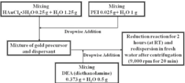
The aqueous gold nanoparticle dispersion was synthesized by chemical reduction method. Reduc- tion reaction was performed by adding the aqueous DEA solution (reduction agent) into the mixture of aqueous gold chloride trihydrate solution mixed with PEI as dispersant, as depicted in the work flow chart shown in Fig. 1. The reduction reaction continued for 2 hours at room temperature and the colloidal dispersion of gold nanoparticles with purple color was generated. The unreacted precursors were removed by centrifugation at 9,000 rpm for 20 min- utes and subsequent washing process in fresh water followed by sonication. In some experiment, PTMAM-
g-PEG was also tested with PEI as co-dis- persant during the chemical reduction process.
2.3. Direct ink writing of gold nanoparticle dispersion on silicon wafer substrate
Direct ink writing of gold nanoparticle dispersion was performed by using concentrated gold nanopar- ticle ink and 3-D robocaster for the precision motion
Fig. 1. The work flow chart of gold nanoparticle synthesis
by chemical reduction method with diethanolamine as
reducing agent and polyethyleneimine as dispersant, wash-
ing and redispersion in fresh water.
control of silicon wafer substrate. The as-synthe- sized aqueous gold nanoparticle dispersion was mixed with ethyleneglycol, which was used as humectants for the ink formulation, followed by evaporation of the dispersion medium, water, at room temperature.
The final concentration of gold nanoparticle ink was adjusted as 9, 30, and 68 wt.% before dispensing the ink solution through the borosilicate nozzle which was fabricated by using laser-based puller (P-2000, Sutter Instruments). The glass tip with 30
µm in diameter was used for the dispensing of gold nanoparticle inks in this study, and 2 to 6 psi of air pressure was applied to the dispensing nozzle during the direct ink writing process. The writing speed was adjusted as 250
µm/
sec for the movement of the robocaster.
2.4. Characterizations and Instrumentations The morphologies of the gold nanoparticles were observed by using a transmission electron micro- scope (JEOL 2010 LaB
6TEM) and the absorbance of the gold colloids was measured with a UV-vis spec- troscopy (Varian, CARY 5G). The crystallinity of the gold nanoparticles was confirmed by X-ray diffrac- tion (XRD) measurement system (Rigaku D-Max).
The particle size distribution of the gold nanoparticle ink was measured by using a photon correlation spec- troscopy (Brookhaven with BI200SM goniometer).
The direct ink writing of the gold ink was performed with a 3-D robocaster (Aerotech, A3200) attached with dispensing unit (800 ultradispensing system, EFD inc.). The precise motion of the 3-D robocaster connected with dispensing unit was controlled by computer-aided design software (RoboCAD, 3D Inks, Stillwater) for the direct ink writing of line pat- terns with 200
µm of line widths. The morphologies of the gold line patterns were observed with a scan- ning electron microscope (JEOL 6060LV SEM).
3. Results and Discussions
3.1.The synthesis of gold nanoparticles by chem- ical reduction method
Fig. 2a contains the photographs of the aqueous
gold nanoparticle dispersion prepared by chemical
reduction method according to the reaction condi-
Fig. 2. (a) The photograph of gold nanoparticle dispersion
before and after the centrifucation and washing for redis-
persion in fresh water according to the procedures shown
in Fig. 1. (b) Transmission electron micrograph (TEM) of
the gold nanoparticles and (c) High magnification TEM
image of gold nanoparticles shown in Fig. 2(a).
tions shown in Fig. 1. After the reaction for 2 hours, the color of the colloidal dispersion became purple, and it became more darker after the washing and redispersion with fresh water, as shown in Fig. 2a.
The morphologies of the gold nanoparticles syn- thesied are displayed in the transmission electron microscope (TEM) images shown in Fig. 2b and 2c.
As shown in the TEM images, the particle shapes are spheroids and the particle size distribution is ranged from 5 to 15 nm. In the magnified TEM image of Fig. 2c, it is possible to observe lattice structures from the gold nanoparticles.
The dispersin stability of the gold nanoparticles synthesized using PEI as dispersant can be explained by steric stabilization mechanism [11]. Since the amine groups attached in the polymer backbone of the PEI have strong affinity with the metal surfaces such as gold nanoparticles, PEI can be adsorbed on the nanoparticle surface, generating the steric barrier between the colloidal particles keeping the interparti- cle distance which is enough to overcome van der Waals force causing the particle aggregation. Simi- larly, polyacrylic acid with carboxyl groups having strong affinity with silver nanoparticle surface has been used as dispersion stabilizer for the synthesis of the silver nanoparticle ink [12].
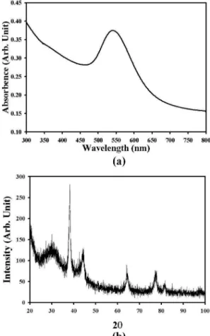
The UV-vis absorption spectrum of the aqueous gold nanoparticle dispersion displayed in Fig. 2 is contained in the Fig. 3a. As shown in the spectrum, the absorption maximum is located in the wave- length of about 550 nm, which is typical for the gold nano-colloid with 48 nm in diameter [13]. This indi- cates the gold nanoparticles shown in the TEM images of Fig. 2b and 2c are aggregates in the solu- tion state into the secondary particles with about 50 nm in diameter. The powder x-ray diffraction result of the gold nanoparticle is displayed in Fig. 3b, exhibiting the metallic face centered cubic structure which can be confirmed from the peak positions.
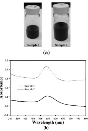
Fig. 4a displays the photographs of the gold nano- particle inks synthesized by increasing the amount of reducing agent as 0.51 g (sample 1) and the dispers-
ant, polyethyleneimine as 0.075 g (sample 2), keep- ing the other synthesis conditions the same as the work flow chart in Fig. 1. The color of the gold nanoparticle inks of sample 1 and sample 2 looks as dark purple and no further improvement of the dis- persion stabilities was confirmed, indicating that the synthesis conditions in Fig. 1 is proper for the gold nanoparticles with 5 to 15 nm in diameter having enough dispersion stability. Fig. 4b contains the UV- vis spectroscopy of the gold nanoparticle inks, sam- ple 1 and sample 2, exhibiting the absorbance peak positions maintained similar to the spectrum shown in Fig. 3a, though the reaction conditions were slightly modified compared to the conditions shown in Fig. 1.
Fig. 3. (a) The UV-vis spectroscopy result of gold nano-
particles synthesized according to the procedures shown in
Fig. 1 and (b) The powder X-ray diffraction result of the
gold nanoparticles.
Fig. 5a displays the photograph of the gold nano- particle ink synthesized by increasing the reduction reaction time as 8.75 hours keeping the other reaction conditions the same as the work flow chart shown in Fig. 1. As shown in Fig. 5a, the as-synthesized gold nanoparticle dispersion reveals poor dispersion stabil- ity with the sedimentation of the precipitated nano- particles. These aggregated particles can be re- suspended by hand-shaking of the dispersion, as shown in the photograph of Fig. 5a. Fig. 5b contains the low magnification TEM image of the gold nano- particle dispersion shown in Fig. 5a. As shown in Fig. 5b, the gold nanoparticles are aggregated into larger secondary particles, indicating that the reduc- tion reaction time is quite long. More magnified
TEM image of the same sample can be seen from Fig. 5c, showing that the nanoparticles with several tens of nanometers are aggregated due to the increased reduction time during the synthesis proce- dure.
Fig. 6a contains the work flow chart for the syn- thesis of the aqueous gold nanoparticle dispersion Fig. 4. (a) The photograph of the gold nanoparticle dis-
persion synthesized with increased amount of reducing agent, diethanolamine (sample 1) and increased concen- tration of dispersant, polyethyleneimine (sample 2) and (b) The UV-vis spectroscopy results of the gold nanoparticle dispersion (sample 1 and sample 2).
Fig. 5. (a) The photograph of the gold nanoparticle dis-
persion synthesized with increased reduction reaction
time. (b) The TEM image of the gold nanoparticle dis-
persion with relatively large secondary particle size and
(c) High magnification TEM image of the gold nanopar-
ticle dispersion shown in Fig. 5(a).
using PEI and PTMAM-
g-PEG as dispersion stabi- lizers. Diethanolamine was used as reducing agent and the chemical reduction reaction was performed with the aids of the mixed dispersants, PEI and PTMAM-
g-PEG. Due to the weak stabilizing effect of the graft copolymer, PTMAM-
g-PEG, the appear- ance of the gold nanoparticle dispersion shown in the picture of Fig. 6b looked dark purple, and the absorption maximum was shifted to the longer wavelength due to the increased particle size com- pared to the gold nanoparticle dispersion stabilized
with PEI alone, as displayed in the UV-vis spectrum of Fig. 6c. It is thought that the PTMAM-
g-PEG can act as flocculant causing the bridging flocculation of the gold nanoparticles stabilized with dispersant such as PEI. Small amount of PTMAM-
g-PEG may cause the aggregation of the gold nanoparticles which are coated with PEI by crosslinking the adsorbed poly- meric stabilizers on the different nanoparticle sur- faces, and further study is underway. This can be the next topic of our research.
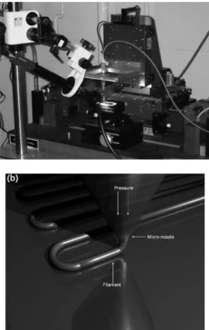
3.2. Direct writing of gold nanoparticle inks Fig. 7a contains the picture of direct ink writing apparatus used in this study attached with dispenser, dispensing nozzle, and optical system to observe the Fig. 6. (a) The work flow chart of gold nanoparticle syn-
thesis by chemical reduction method with diethanolamine as reducing agent and PEI/PTMAM-
g-PEG as dispers- ants, washing and redispersion in fresh water. (b) The pho- tograph of the gold nanoparticle dispersion synthesized according to the procedures shown in Fig. 6(a) and (c) The UV-vis spectroscopy of the gold nanoparticle dispersion sample shown in Fig. 6(b).
Fig. 7. (a) The photograph of the direct ink writing appa-
ratus used in this study and (b) The schematic figure for
the fabrication of the precise line patterns with direct writ-
ing apparatus.
precise motion of 3-axis stage controlled by com- puter [12]. The proper ink materials can be depos- ited on the substrate during the direct writing process to fabricate microstructures with designed morpholo-
gies. Fig. 7b displays the schematic figure for the capillary nozzle dispensing the ink materials on the substrate during direct writing procedures for the fabrication of precise line patterns. In this study, we have utilized this apparatus to test the writing capa- bility of the synthesized gold nanoparticle inks and the resultant microstructures were obtained using the direct writing machine, robocaster.
The gold nanoparticle dispersion synthesized by chemical reduction method was concentrated by evaporating the dispersion medium at room tempera- ture to obtain high solid concentration of the solid particles with 68 wt.%. During this concentrating pro- cedure, the secondary particle size of the gold nano- particle dispersion was increased to 192.2 nm as shown in the particle size distribution in Fig. 8a. The size limitation of the gold nanoparticles for the dis- pensing the ink through the nozzle depends on the operating pressure of the dispenser. When the dis- pensing pressure is larger than O(10
3) psi, very con- centrated ink made of micro-powders can be deposited on the substrate by direct ink writing process using dispensing nozzle with 250
µm in diameter [14]. How- ever, when the inner diameter of the dispensing tip is as small as 30 nm in diameter and the operating pressure of the dispenser is smaller than 100 psi, it will be quite difficult to use ink having secondary particle size of the constituent particles with micron size. In this study, the concentrated gold nanoparti- cle ink was dispensed through the glass capillary nozzle with 30 nm in diameter and the line pattern was precisely fabricated using robocasting appara- tus. Fig. 8b contains the optical image of the dis- pensing tip and the gold line patterns with 200
µm inter-pattern width. As shown in this picture, the direct writing of the gold nanoparticle ink was suc- cessful without the spreading of the ink materials on the silicon wafer substrate and the abscission of the line patterns. Fig. 8c displays the optical image of the line patterns during the stop and repeat writing of the same gold nanoparticle ink, exhibiting that the intentional fabrication of the short lines is possible Fig. 8. (a) The particle size distribution of the gold nano-
particle dispersion for the direct ink writing process (DIW).
(b) The optical microscope image of the line patterns of
gold nanoparticle ink fabricated by DIW process and (c)
The optical microscope image of gold nanoparticle ink
with stop and repeat writing of DIW process.
with the nanoparticle ink and the robocasting equip- ment.
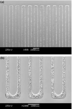
Fig. 9a contains the scanning electron microscope image of the line patterns made of gold nanoparticle
ink shown in the optical image of Fig. 8b. The microstructure of the precise line patterns was also confirmed using scanning electron microscope with more magnified image shown in Fig. 9b. The well- defined line patterns of the gold material have been successfully fabricated using direct writing process.
Fig. 10 contains the microstructures of the line pat- terns made of gold nanoparticle inks with various solid concentrations. As shown in the scanning elec- tron microscope images in Fig. 10a and 10b, the solid coverage on the silicon wafer substrate is quite low for the case of the gold nanoparticle concentra- tion such as 9 and 30 wt.%. This incomplete cover- age can be improved by increasing the solid content of the gold nanoparticle ink with 68 wt.% as dis- played in the scanning electron microscope image of Fig. 10c.
4. Conclusions
The aqueous gold nanoparticles were synthesized by chemical reduction method using diethanolamine as reducing agent and polyethyleneimine as disper- sion stabilizer. The synthesis conditions have been studied for the stable gold nanoparticle suspension without flocculation. The synthesized gold nanopar- ticle dispersions were mixed with humectants, ethyl- eneglycol, and concentrated by evaporating the dispersion medium at room temperature to obtain the gold nanoparticle inks for direct ink writing process.
Fig. 9. (a) The scanning electron micrograph of line pat- terns of gold nanoparticles fabricated by DIW process and (b) More magnified SEM images of the same line patterns.
Fig. 10. The scanning electron micrographs of the line patterns of gold nanoparticles with different amount of the solid con-
tents.
The optimum solid content to fabricate precise gold line patterns were determined by varying the con- centration of the nanoparticles in the ink materials.
Using 3-axis robocaster and dispensing apparatus, microstructures such as line patterns were success- fully fabricated with gold nanoparticle inks as start- ing materials.
Acknowledgments
This research was supported by a grant(code #:
2010K000270) from ‘Center for Nanostructured Mate- rials Technology’ under ‘21
stCentury Frontier R&D Programs’ of the Ministry of Education, Science and Technology, Korea. This work was also partially sup- ported by a grant from ‘Basic Research (PNK2210) in Korea Institute of Materials Science (KIMS)’. The authors thank to Dr. Bok Yeop Ahn for many stimu- lating discussions on the synthesis of the gold nano- particle inks and direct ink writing process.
References
[1] M. Oda and J. Surf: Finishing Soc. Jpn.,
47(1996) 910.
[2] http://www.utilisegold.com/assets/file/utilisegold/pdf/
JM.pdf
[3] J. B. Szczech, C. M. Megaridis, J. Zhang, and D. R.
Gamota: Nanosc. Microsc. Thermophys. Eng.,
8(2004) [4] J. J. Sotrhoff, R. Elghanian, R. C. Mucic, C. A. Mirkin 327.
and R. L. Letsinger: J. Am. Chem. Soc.,
120(1998) 1959.
[5] Y. Sun, A. I. Frenkel, H. White, L. Zhang, Y. Zhu, H.
Xu, J. C. Yang, T. Koga, V. Zaitsev, M. H. Rafailovich and J. C. Sokolov: J. Phys. Chem. B,
110(2006) 23022.
[6] P.-Y. Silvert, K. and Tekaia-Elhsissen: Solid State Ion- ics,
82(1995) 53.
[7] T. Li, H. G. Park and S.-H. Choi: Mater. Chem. Phys.,
105
(2007) 325.
[8] A. Iwakoshi, T. Nanke and T. Kobayashi: Gold Bull.,
38