• 검색 결과가 없습니다.

Effects of the Intake Valve Timing and the Injection Timing for a Miller Cycle Engine

N/A
N/A
Protected

Academic year: 2021

Share "Effects of the Intake Valve Timing and the Injection Timing for a Miller Cycle Engine"

Copied!
7
0
0

로드 중.... (전체 텍스트 보기)

전체 글

(1)

To whom corresponding should be addressed.

Department of Mechanical & Automotive Engineering, Induk University, San 76 Wolgye-dong, Nowon-gu, Seoul 139-749, Korea

E-mail : [email protected]

Effects of the Intake Valve Timing and the Injection Timing for a Miller Cycle Engine

Sung Bin Han*

, Yong Hoon Chang*, Gyeung Ho Choi**, Yon Jong Chung***, Chedthawut Poompipatpong**** and Saiprasit Koetniyom****

*Department of Mechanical & Automotive Engineering, Induk University, Seoul 139-749, Korea

**EROOM G & G Co., Ltd, Seoul, Korea

***Department of Automotive Engineering, Daegu Mirae College, Kyongbuk 573-701 Korea

****Science in Automotive Engineering, King Mongkut’s Institute of Technology North Bangkok, Thailand (Received 09 December 2009, Revised 12 May 2010, Accepted 26 March 2010)

Abstract ― The objective of the research was to study the effects a Miller cycle. The engine was dedicated to natural gas usage by modifying pistons, fuel system and ignition systems. The engine was installed on a dynamometer and attached with various sensors and controllers. Intake valve timing, engine speed, load, injection timing and ignition timing are main parameters. Miller Cycle without supercharging can increase brake thermal efficiency 1.08% and reduce brake specific fuel consumption 4.58%. The injection timing must be synchronous with valve timing, speed and load to control the performances, emissions and knock margin. Throughout these tested speeds, original camshaft is recommended to obtain high volumetric efficiency.

Key words : Miller cycle, Natural Gas Engine, Intake valve timing, Injection timing, Ignition timing, Emissions

1. Introduction

There are many previous researches about natural gas engine. In addition, most of them focus on the studying of improving the engine performance and emission. Anderson et al investigated on naturally aspirated Miller cycle spark ignition engine with LIVC(Late Intake Valve Closure) based on the first and second law of thermodynamic analysis. They assumed that the cylinder was divided into two zones, unburned and burned zone. The properties of each zone was uniform. Combustion was modeled as a turbulent flame. Heat transfer, homogeneous mixture, temperature etc. were considered as well. They found that LIVC required less fuel to produce the same output and could achieve up to 6.3% higher

indicated thermal efficiency at part load. LIVC had thermo-mechanical advantage due to higher intake manifold pressure [1,2,3].

Bassett et al simulated a simple and cost effective mechanism that allows two-state LIVC control. This device allowed the engine to operate with wider than normal throttle settings at low load, which reduced pumping losses. They installed a reed valve in the intake manifold. At full load, reed valve prevented the charge from being rejected out from the cylinder. At low load, the reed valve allowed the charge to return freely.

This can reduce BSFC(Brake Specific Fuel Consumption) around 7% and also reduce NO

x

[4,5].

Shiga et al [6] found that the intake capacity cham-

ber installation reduced the pumping loss by apply-

ing LC(Late Closing). They varied the valve timing

and compression ratio. They found that the pumping

loss trend was not really affected by the expansion

ratio but it was mainly affected by intake valve ti-

ming. And pumping loss could be decreased by LC.

(2)

(a) compression ratio of 22 (b) compression ratio of 9 Fig. 1. The original and modified pistons.

The experiment results could be explained by calcu- lations that the expansion ratio was ten times as effec- tive as the compression ratio in increasing the ther- mal efficiency.

Wu et al [7] simulated Miller cycle with and without supercharger. The pressure and temperature at the end of compression process were lower. Then they ass- umed the intake pressure to be 110 kPa for super- charge Miller cycle. They still found that tempera- ture at the end of compression stroke was lower than those of Otto cycle without supercharger. Then they simulated the Mazda engine that operated on Miller cycle. The pressure of supercharger was 196.5 kPa which was higher than they simulated. The result was that there was more mass in the cylinder, higher MEP(Mean Effective Pressure) and more net work output. They suggested that Miller cycle should ope- rate with supercharger.

Lee et al researched on the thermal efficiency on an industrial engine with Miller cycle. A diesel en- gine was retrofitted to natural gas engine for better durability. He changed the closing time of intake valve for adapting Miller cycle. Intake cam lift compen- sation test was added on the EIVC test and also eff- ective compression pressure compensation test was added on the LIVC test. He found that EIVC had less thermal efficiency than the basic cam experi- ment. LIVC test at 51 degree ABDC(After Bottom Dead Center) improved the fuel consumption ratio around 5-8% and brake thermal efficiency around 2- 3%. LIVC test at 77 degree-ABDC improved the fuel consumption ratio and brake thermal efficiency around 3-7% and 1-2% respectively. The NO

x

emi- ssion decreased by 5-10% [8,9,10].

Research on the effects of combustion chamber sha- pe, air-fuel ratio, type of injection, injection timing, compression ratio, valve timing and ignition timing have been done for long time. For a specific natural gas dedicated diesel engine(spark-ignition engine) which is tested at a specific compression ratio, the effects of valve timing and injection timing on the efficiencies and emissions seem to be interesting.

The objectives of the work were to study the infl-

uence of intake valve timing and injection timing in a natural gas diesel engine. And also to find the ten- dency of engine efficiency in different intake valve closures and injection timings. In this research, the effects of load, speed, intake valve timing and in- jection timing on the efficiencies and emissions will be studied under the compression ratio(expansion ra- tio) of nine, speed of 1500 rpm, 2000 rpm and 2500 rpm with the equivalent air-fuel ratio of 1.0.

2. Experimental methodology

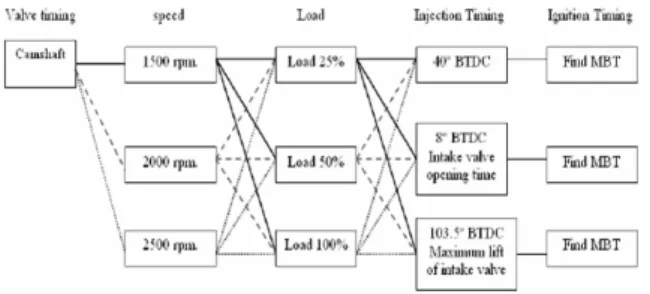
A diesel engine was dedicated for using with na- tural gas by modifying the pistons. Compression ra- tio was been reduced to 9. Fuel pump and fuel in- jectors are replaced by spark plugs. The engine was installed to an eddy current dynamometer. This ex- periment was mainly to compare the intake valve clo- sing timing. Changing camshaft profiles was the way to this experiment. Therefore, this experiment need- ed three different camshafts. Each camshaft was also tested in various loads. Every load, three different injection timings were tested to achieve the objec- tive. In each injection time, many ignition timings were tested to find the MBT.

A diesel engine, Daedong 4A220A-S1, was totally

dedicated to natural gas diesel engine with natural

gas injectors and close loop controller. The pistons

were redesigned from the diesel compression ratio

of twenty-two to the compression ratio of nine as

shown in Figure. 1 Diesel pump and injectors were

replaced by spark plugs. Table 1 shows the dedi-

(3)

Table 1. Natural gas diesel engine specification.

Type 4-cylinder, 4-stroke engine

Displacement, cc 2,197

Bore, mm 87

Stroke, mm 92.4

Compression ratio 9.0

Fuel supply system Gas injectors

Fig. 2. Schematic diagram for the test engine.

Fig. 3. Data collecting arrangement.

Fig. 4. Effect of intake valve timing on the power output.

Fig. 5. Effect of intake valve timing on the SFC.

cated engine specification.

This research was focusing on the intake valve ti- ming and injection timing. Therefore, three camsha- fts are used for giving three different valve timings.

Each valve timing was tested in 25%, 50% and 100%

loads. The speeds of 1500, 2000 and 2500 rpm are experimented in each load. Three different injection timings are tested in every speed. MBT was found by changing the ignition timing. The compression ratio of nine and equivalent air-fuel ratio of 1 are the test condition. The ignition timings were varied bet- ween 15 and 54 degree BTDC with the interval of 3 degrees. Therefore, to complete the experiment, en-

gine testing must go over all the processes of three times. Before collecting the data in each ignition ti- ming, the engine must be running under the condi- tion of equivalent air-fuel ratio of 1(air-fuel ratio of 16.83). So adjusting the amount of injected natural gas was needed. The dynamometer control program collected the output data such as power, torque, en- gine speed, temperature, etc(See Figure. 3).

3. Results and discussions

3-1. Effects of Intake valve timing

Figure. 4 to 6 are the test result at 2000 rpm, WOT(Wide Open Throttle) at the injection timing of 40º BTDC. These graphs show the trend of brake power, SFC and brake thermal efficiency according to the change in ignition timing. The lowest SFC and highest brake thermal efficiency occur at MBT ignition timing. In every tested speed and injection timing and the output power from camshaft No.1 is higher than camshaft No.2. In addition, the result from camshaft No.2 is higher than camshaft No.3.

The gap between each graph line is getting closer

with engine speed. It might be predicted that in high

speed, the output from camshaft No.2 can be higher

than camshaft No.1. The explanation for this can be

(4)

Fig. 6. Effect of intake valve timing on the brake thermal efficiency.

Fig. 7. Effect of intake valve timing on the THC emission.

Fig. 8. Effect of intake valve timing on the NO

x

.

Fig. 9. Effect of intake valve timing on the CO.

Fig. 10. Effect of intake valve timing on the CO

2

at 1500 rpm.

Fig. 11. Effect of intake valve timing on the CO

2

at 2000 rpm.

Fig. 12. Brake thermal efficiency versus ignition timing at 2500 rpm.

discussed in term of the unit air charge as follow.

In addition, the higher effective compression ratio in camshaft No.1 increases the combustion chamber temperature, which results in higher NO

x

emission as shown in Figure. 7 and 8.

This experiment cannot clearly indicate the effect of valve timing on the CO emission as shown in Figure. 9 There is no significant change in CO emission according to the change in the intake valve timing

or ignition timing.

In the speed of 1500 rpm, combustion from camshaft No.1 seems to emit higher CO

2

as shown in Figure.

10 While speed increases to 2000 rpm and 2500 rpm, the result has a little change as shown in Figure. 11.

The results are plotted versus ignition timing in Figure. 12 to 14 Camshaft No.3, LIVC at 77ºABDC, the brake thermal efficiency of camshaft No.3 is hi- gher than the that of camshaft No.2, LIVC at 51º ABDC, up to 0.42% in the injection timing of 40º BTDC as shown in Figure. 12.

After the injection timing was changed to 8ºBTDC

and 103.5ºATDC, Figure. 13 and 14 present an in-

crement of brake thermal efficiency of camshaft No.2

and 3 over the original camshaft(camshaft No.1). Fi-

(5)

Fig. 13. Brake thermal efficiency versus ignition timing 2500 rpm.

Fig. 14. Brake Thermal Efficiency versus Ignition Timing.

Fig. 15. Effect of injection timing on power.

Fig. 16. Effect of injection timing on SFC.

Fig. 17. Effect of injection timing on brake thermal effi- ciency.

gure 14 shows that the maximum brake thermal effi- ciencies of camshaft No.1 and 2 are 22.55% and 23.63% respectively. That is increased by 1.08%.

While Figure. 14 shows an increment of 0.36%. The data also presents the benefit in term of SFC, which are 4.58% and 1.58% for the injection timing of 8º BTDC and 103.5ºATDC respectively. Enumerating again, the only change from Figure. 12 to 13 and Figure. 14 is the injection timing. This is evidence that Miller Cycle can improve brake thermal efficiency if it works with appropriate injection timing.

3-2. Effects of Injection Timing

Injection timing is another important issue. How- ever, this research found that injection timing has small effect on the output performance as shown in Figure. 15 The reason might be that the fuel is ga- seous, which has less difficulty in mixing up with air. The other reason could be that the injection ti- mings in this experiment are not too late. However, late injection timing was tested at the intake valve closing time. The results were not collected because the engine conditions were severe. The knocking sound occurred with high exhaust emissions. Thus, the expe-

riment of this injection timing did not go on. Never- theless, this was a very useful experience in analy- zing the effects of injection timing in a natural gas diesel engine.

Figure. 16 and 17 are to review the discussion in the previous topic about the influence of injection ti- ming. According to the whole data, it is not possible to find the exact influence on brake thermal effici- ency and specific fuel consumption.

Figure. 18 and 19 show the effect of injection ti- ming on exhaust THC and NO

x

emissions. Camshaft No.3 can indicate a small effect that injection timing of 103.5°ATDC gives slightly higher in THC and NO

x

emissions. A very interesting point in the injection timing is the effect on knocking. This experiment fo- und a knocking in camshaft No.3.

The data of CO and CO

2

also show the frustra-

(6)

Fig. 18. Effect of Injection Timing on THC.

Fig. 19. Effect of injection timing on NO

x

.

Fig. 20. CO

2

at 1500 rpm 25% load for camshaft No.2.

Fig. 21. CO

2

at 1500 rpm 50% load for camshaft No.2.

Fig. 22. CO at 1500 rpm 25% load for camshaft No.2.

Fig. 23. CO at 1500 rpm 50% load for camshaft No.2.

ting result, shown in Figure. 20 to 23. For camshaft No.1 at 1500 rpm 25% load, the 103.5°ATDC injec- tion timing gives out the highest CO

2

. When the load changes to 50%, it shows the lowest. The result of CO mainly opposite to the CO

2

because if CO reacts with O

2

and becomes CO

2

, the amount of CO will decrease and increase amount of CO

2

. The result cannot bring to the clear answer of the effect of injection timing. Because this experiment proved that,

the injection timing must operate synchronously with each particular valve timing, engine speed and load.

Therefore, the effects of injection timing must be re- searched in a very well prepared methodology to give a useful result.

4. Conclusions

The result can be different in case of being be- yond this scope. The following conclusions have been reached:

(a) Higher load comes with higher power, torque, volumetric efficiency, SFC, THC, NO

x

and CO while brake thermal efficiency and CO

2

are lower. Engine speed affects the heat loss, fric- tion loss and volumetric efficiency, which affect output torque. Engine speed limits the combu- stion time, which raises the exhaust gas tem- perature around 50ºC for every increment of 500 rpm.

(b) Camshaft No.1, 2 and 3 can obtain the maxi-

mum volumetric efficiency, if they are opera-

ted at WOT. At 25% load and the speed of

2500 rpm, camshaft No.2 can increase the brake

thermal efficiency 1.08% and reduce brake spe-

cific fuel consumption up to 4.58% comparing

(7)

to the original camshaft(camshaft No.1). This condition must be operated only with the in- jection timing of 103.5ºATDC.

REFERENCES

1. Anderson, M. K., Assanis, D. N. and Filipi, Z. S.

(1988). First and second law analyses of a natural- aspirated, miller cycle, SI engine with late intake valve closure. SAE paper No. 980889.

2. Tsukida, S., et al., “Production Miller-Cycle Natural Gas Engine.” Inter- Tech Energy Progress, Inc.. (1999). 1-9.

3. Caton, J. A. “Effects of the compression ratio on nitric oxide emissions for a spark ignition engine : results from a thermodynamic cycle simulation.” Int.

J. Engine Res.. Vol. 4 No. 4(2003). 249-268.

4. Basset, M. D., Blakey, S. C. and Foss, P. W. (1997).

A simple two-state late intake valve closing mecha- nism.” Proc. Instn. Mech. Engrs, 211, 237-241.

5. Akira, T., et al., “Mitsubishi Lean-Burn Gas Engine with World’s Highest Thermal Efficiency.” Mitsubishi

Heavy Industry, Ltd. Technical Review.” Vol. 40 No. 4 (Aug. 2003). 1-6.

6. Shiga, S., Hirooka, Y., Miyashita, Y., Yagi, S., Mac- hacon, H. T. C., Karasawa, T. and Nakamura, H(2001).

Effect of over-expansion cycle in a spark-ignition en- gine using late-closing of intake valve and its thermo- dynamic consideration of the mechanism. Int. J. Auto- motive Technology. 2, 1. 1-7.

7. Wu, C., Puzinauskas, P. V. and Tsai, J. S. (2003).

Performance Analysis and Optimization of a Super- charged Miller Cycle Otto Engine. Applied Thermal Engineering, 23, 511-521.

8. Lee, J. H. (2006). A Study of the Thermal Efficiency on the Industrial Engine with Miller Cycle. Master Thesis, Keimyung University. Department of Auto- motive Engineering. Korea.

9. Koichi, H., et al., “A study of the improvement effect of Miller-cycle on mean effective pressure limit for high-pressure supercharged gasoline engines.” JSAE.

18(1997). 101-106.

10. Sarki, A. A., et al., “Efficiency of a Miller Engine.”

Applied Energy. (2005). 1-9.

수치

Fig. 4. Effect of intake valve timing on the power output.
Fig. 17. Effect of injection timing on brake thermal effi- effi-ciency.
Fig. 22. CO at 1500 rpm 25% load for camshaft No.2.

참조

관련 문서

 false path : instruct the synthesis to ignore a particular path for timing optimization.  multicycle path: inform the synthesis tool regarding the number of clock cycles

A jet pump is a fluid carrying device which spouts fluid of high pressure from a driving engine pipe and absorbs fluid of high pressure whose pressure

¡ 작동 범위 내에서의 어떠한 점도 MCR이 될 수 있으나, MCR을 선정할 때는 마력과 회전수의 Derating 값(MCR, NMCR에서 마력과 회전수의 차이), 프로펠러 회전수,

In terms of the mould design, the effects of runner system design and the mould temperature on filling characteristics, the weldline formation, the

¨ Use alternative project finance and delivery methods across collections of infrastructure projects. ¨ Strategic opportunities to affect the timing, quality, and cost

 A series of systems for configuring alarm and control functions by monitoring the states of main engine, generator, and auxiliary equipment, for securing the safety

– Reversible cyclic process with Ideal gas – Maximum efficiency of a

It was found that the NO emission decreased significantly at various condition of operation with the 2-stage combustion type diesel engine, but CO and