한 국 방 재 학 회 논 문 집 제10권 3호 2010년 6월
pp. 39 ~ 43
도로교통방재
Development of Fatigue Performance Model of Asphalt Concrete using Dissipate Energy
Kim, Nakseok*
···
Abstract
The main objective of this research is to develop a mechanistic performance predictive model for fatigue cracking of asphalt- aggregate mixtures. Controlled-stress diametral fatigue tests were performed to characterize fatigue cracking of asphalt-aggregate mixtures. Performance prediction model for fatigue cracking was developed using the internal damage ratio (IDR) growth method.
In the IDR growth method, the general concepts of the dissipated energy, the reference tensile strain, the threshold tensile strain, and the strain shift factor were introduced. The source of the dissipated energy in the fatigue test is from the intrinsic viscoelastic material property of an asphalt concrete mixture and the damage growth within the asphalt concrete specimen. In controlled-stress mode test, the dissipated energy is gradually increased with an increasing number of load applications.
Key word : Fatigue, Performance Model, Dissipated Energy, Threshold Tensile Strain
요 지
본 연구의 주목적은 아스팔트 혼합물의 피로균열에 대한 예측모델을 개발하는 것이다. 아스팔트 혼합물의 피로균열 시험을 위하여 응력제어 간접인장피로 시험이 수행되었다. 피로균열에 대한 예측모델 개발을 위하여 내적손상비 증가 개념이 도입되었다. 내적손상비증가 개념에서는 방출에너지 개념을 주로 사용하였으며 기준인장변형율 및 변형율 추이 요소 등이 추가로 사용되었다. 피로시험에서 나타난 방출에너지의 원인은 아스팔트 콘크리트 시료 내부의 손상증가와 재료 자체가 갖고 있는 고유의 점탄성 특성에 기인하는 것으로 판단된다. 방출에너지는 하중재하 횟수가 증가함에 따 라 점차 증가함을 보였다.
핵심용어 : 피로, 공용모델, 방출에너지, 기준인장변형율
···
1. Introduction
During the past years, an extensive amount of pavement research has focused on the development of performance prediction models on fatigue cracking in asphalt concrete pavements. The reason for this extensive research is an implicit recognition that fatigue cracking is the most com- mon type of distresses encountered in flexible pavements.
Accurate prediction of the progression of this distress is imperative to provide a safe and durable surface for traffic during the design life.
The fatigue characteristics of asphalt mixtures have been described traditionally as a relationship between the number of load repetitions to failure and some significant engineer- ing parameters. Various efforts have been made to find out the most significant engineering parameters which dominate the general fatigue performance of asphalt concrete pave-
ments. These efforts have produced many phenomenological or mathematical fatigue models.
The main objectives of this research are as follows:
(1) To recognize how damage to the asphalt-aggregate mixtures actually develops as loading accumulates during the fatigue test.
(2) To develop performance predictive model on fatigue cracking in asphalt-aggregate mixtures for mechanistic flex- ible pavement design methods.
2. Materials and Specimen Preparation
The asphalt cement used in this research was AC-20 asphalt, and the level of asphalt content for the asphalt cement was determined. According to the construction record maintained by the NCDOT, the optimum asphalt contents of the heavy duty surface (HDS) and the heavy
*Member·Professor, Kyonggi University, Department of Civil Engneering (E-mail : [email protected])
duty binder (HDB) courses were determined using the U.S.
Army Corps of Engineers (Marshall) 75-blow procedure (ASTM D 1559). The procedure required a minimum 1,500 Marshall stability.
On the other hand, the optimum asphalt content of the asphalt-stabilized base course (HB) was determined using the U.S. Army Corps of Engineers (Marshall) 50-blow pro- cedure. The procedure required a minimum 800 Marshall stability. The aggregates used in this research were #67,
#467, #78M, SCRG., and Sand. To get three type of mix- tures (HDS, HBD, and HB), these aggregates were blended properly in certain proportions.
The compaction efforts were adjusted based on the target air void content of the specimen. In this research, the target air void content of the specimen was six percent with a Wet- With-Parafilm(WWP) measurement procedure regard less of the specimen size or mixture type. This target air void con- tent of the specimen was selected based upon the air void content measurements from the field core specimens. Gen- erally, the air void contents from the field core specimens were in the wide range of four to eight percent.
The air void content measurement was done in accordance with the new method, “Wet-With-Parafilm (WWP)” devel- oped by the researchers at the University of California, Ber- keley as a part of the SHRP Project A-003A(Kim, N., 1991;
Kim, Y.R. et al., 1992). The haversine load with 0.05 sec- ond load duration and 0.45 second rest period was repeated until the specimen “failed.” The stress amplitude was kept constant throughout testing, and time histories of horizon- tal and vertical deformations were recorded at the 200th cycle.
3. Development of Fatigue Prediction Model
Fig. 1 demonstrates a typical hysteresis loop from a diametral fatigue test in the controlled-stress mode(Kim, N, 1994; Tayebali, A.A. et al., 1993; van Dijk, W. et al., 1997).
The dissipated energy is defined as the area inside the hys- teretic stress-strain loop; that is,
(1) where w = dissipated energy at a certain load cycles, where s = applied stress, and
where dε = corresponding infinitesimal strain changes.
It must be noted that the dissipated energy is due not only to damage growth in the system but also to the history- dependence of the material(Kim, N., 1994; Tayebali, A.A. et al., 1992). In fact, it can be easily shown using theory of viscoelasticity that most of the dissipated energy in earlier cycles is due to the history-dependent nature of the material.
Fig. 2 presents the variations of dissipated energy with an increasing number of load applications in a controlled-stress mode test. This figure shows that the dissipated energy remains relatively constant until the dramatic increase near the failure.
When an asphalt concrete pavement is subjected to repet- itive random wheel loads (varying load levels with different rest periods), two principal mechanisms take place within the asphalt concrete:
(1) relaxation of stresses in the material due to the vis- coelastic nature of asphalt concrete and (2) damage accumu- lation. If the applied stress level in the diametral test is as low as that in the resilient modulus test which is called a nondestructive test, the major portion of the dissipated energy is generated because of the time-dependent vis- coelastic property of the asphalt concrete mixture.
3.1 Damage Growth Approach
Based on these conceptual backgrounds discussed above, the internal damage ratio(IDR) at a certain number of load
w=∫σ εd
Fig. 1. Typical stress-strain hysteresis loop at 0oC
Fig. 2. Dissipated energy versus number of load repetitions in controlled-stress tests.
repetitions is defined as the ratio of the dissipated energy change
(2) where IDRn = internal damage ratio at n-th load repetition where wn = dissipated energy at n-th load repetition, and where wi = initial dissipated energy at 200th cycle.
In the initial stage of the fatigue tests, the dissipated energy from the hysteresis loop reaches the steady state in controlled-stress mode tests. However, the dissipated energy increases with the increase in number of load repetitions due to the damage accumulation within the specimen after a cer- tain period of the initial steady state. Therefore, the change in dissipated energy (wn-wi) at a certain number of load rep- etitions after the steady state is attributed to the damage growth within the specimen. In addition, the normalization of the internal damage ratio by dividing the dissipated energy change by the initial dissipated energy makes it pos- sible to describe the internal damage ratio growth as a func- tion of the number of load repetitions. That is, the growth of internal damage ratio defined in Eq. (2) can be expressed with similar mathematical form regardless of the testing conditions and the mixture variables.
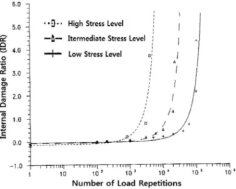
To estimate the internal damage ratio growth of the spec- imen with the increasing number of load applications during the test, the internal damage ratio was plotted against the number of load repetitions on a semi-log scale. The general trend of the internal damage ratio with an increasing number of load applications is expressed with an appropriate expo- nential form. Namely, regardless of the testing conditions and the mixture variables in this research, the growth in the internal damage ratio showed an exponential trend. As an example, Fig. 3 presents the general trend of the internal damage ratio with an increasing number of load applications
with HDS mixture at 0oC.
Thus, the growth of the internal damage ratio with an increasing number of load repetitions can be described with the following mathematical form:
(3) where IDRn = internal damage ratio at n-th load repetitions, where A = regression coefficient (approximatley one), where B = damage growth indicator
where Nn = n-th number of load applications.
3.2 Growth of Internal Damage Ratio
Preliminary study on the relationship between different test parameters and the horizontal shift has suggested that the initial tensile strain at 200th cycle can be used in con- structing the shift factor.
The horizontal tensile strain shift factor (αε) is defined as:
(4) where aε = tensile strain shift factor,
where Nεi = fatigue life at a certain tensile strain level, and where Nεr = fatigue life at reference tensile strain level.
Rearranging Eq. (4) we obtain:
(5) For the reference internal damage ratio curve, Eq. (3) can be expressed as follows:
(6) Substituting Eq. (5) into Eq. (6) yields:
(7) Eq. (7) is a internal damage ratio growth equation for the entire fatigue life in the reference condition. In this research, the failure is defined as the moment when IDR reaches a critical value of IDRc. Thus, when IDR = IDRc, N=Nf.
Applying this failure criterion to Eq. (7) results in:
(8) Rearranging Eq. (8) produces:
(9) where Nf,εi = fatigue life at a certain initial tensile strain level, where IDRr,c = critical internal damage ratio,
where Nεr = regression constant (approximately one), where aε = tensile strain shift factor
where Br = damage growth indicator at reference strain.
IDRn wn–wi wi
---
=
IDRn=Aexp(B Nn)–1
aε Nεi Nεr
---
=
Nεr Nεi aε
---
=
IDRr=Arexp(BrNεr)–1
IDRr ArexpBraNεi ---ε
⎝ ⎠
⎛ ⎞
=
IDRr c, Arexp BrNaf εi, ---ε
⎝ ⎠
⎛ ⎞–1
=
Nf εi, aε Br
--- IDRr c, +1
Ar
---
⎝ ⎠
⎛ ⎞
ln
=
Fig. 3. Internal damage ratio versus number of load applications with HDS mixture at 0oC.
3.3 Tensile Strain Shift Factor
The general concept of the threshold tensile strain is illus- trated in Fig. 4 As shown in the figure, the threshold tensile strain level at 0oC should be higher than that at 20oC since the elastic range of the tensile strain increases as the tem- perature decreases. Also, it explains that the number of load repetitions to failure can be infinite with the application of a certain threshold tensile strain to the specimen. In this research, a certain initial tensile strain which results in an infinite fatigue life was defined as the threshold tensile strain.
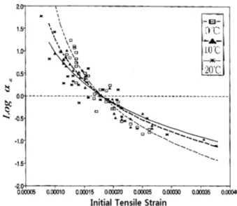
Fig. 5 was plotted with the introduction of the selected threshold tensile strains. Regardless of the effect of the mix- ture type, the figure was plotted and the advantage of the introduction of the threshold tensile strain is shown.
Namely, the regression curves can fit better the points plot- ted at higher fatigue life.
From the regression analysis with the threshold tensile strains defined above, the general function of the tensile strain shift factor (αε) can be expressed as follows:
(10) where αε = fatigue life at a certain initial tensile strain level, where εi = critical internal damage ratio,
where εth = regression constant (approximately one), where εr = tensile strain shift factor
where T = damage growth indicator at reference strain.
To properly relate the nine reference damage growth indi- cators with the relationships of appropriate engineering parameters, various approaches have been executed. Fig. 6 suggests that the reference damage growth indicators are not temperature dependent, but mixture type dependent.
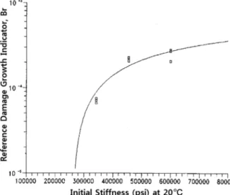
Thus, the reference damage growth indicators were related to the initial mixture stiffness (Si) as shown in Fig. 7.
The reference damage growth indicators at the reference tensile strain can be related to the following function:
(11) where Br = reference damage growth indicator and where Si= initial stiffness (psi) at 20oC.
Substituting Eq. (10) and (11) into Eq. (9) generates the general fatigue equation as follows:
aε (2.130 10× –5T1.124)log
εi–εth
εr–εth
---
⎝ ⎠
⎛ ⎞
=
Br=–4.056 10× –3+7.470 10× –4log( )Si
Fig. 4. General concept of threshold tensile strain(Kim, N., 1994).
Fig. 5. Log versus initial tensile strain with introduction of threshold tensile strain at three temperatures(0, 10, and 20oC).
Fig. 6. Reference damage growth indicator (Br) versus temperature.
(12)
where Nf,εi = fatigue life at a certain initial tensile strain level, where T = critical internal damage ratio,
where εi = regression constant (approximately one), where εth = tensile strain shift factor, and
where εr = reference tensile strain, and
where Si= damage growth indicator at reference strain.
4. Conclusions
New performance prediction model on fatigue cracking of asphalt-aggregate mixtures was developed through extensive laboratory material characterization. Within the limits of this study, the following principal conclusions can be drawn:
1) The source of the dissipated energy in the fatigue test is from the intrinsic viscoelastic material properties of
an asphalt-aggregate mixture and the damage growth within the asphalt concrete specimen.
2) The main reason of gradual increasement in dissipated energy with an increasing number of load applications is due to the development of internal damage growth in the asphalt concrete specimen.
3) The basic concept of cumulative dissipated energy dur- ing the fatigue test has been applied to modeling of fatigue cracking in asphalt-aggregate mixtures.
Acknowledgement
This work was supported by Kyonggi University Research Grant 2009.
References
Kim, N. (1991) Effect of Temperature and Mixture Variable on Fatigue and Permanent Deformation of Asphalt Concrete, Mas- ter Thesis, North Carolina State University.
Kim, N. (1994) Development of Performance Predict Models for Asphalt Concrete Layers, Ph. D. Dissertation, North Carolina State University.
Kim, Y.R., Kim, N., and Khosla, N.P. (1992) Effect of Aggregate Type and Gradation on Fatigue and Permanent Deformation of Asphalt Concrete, Published in 1992 ASTM STP 1147.
Tayebali, A.A., Deacon, J.A., Monismith, C.L. (1993) Modeling Fatigue Response of Asphalt-Aggregate Mixtures, Proceedings, Association of Asphalt Paving Technologists.
Tayebali, A.A., Rowe, G.M., and Sousa, J.B. (1992) Fatigue Response of Asphalt-Aggregate Mixtures, Proceedings, Associ- ation of Asphalt Paving Technologists.
van Dijk, W. and Visser, W. (1997) The Enery Approch to Fatigue for Pavement Design, Proceeding, Association of Asphalt Pav- ing Technologists, Vol.44.
◎논문접수일 : 10년 04월 23일
◎심사의뢰일 : 10년 04월 26일
◎심사완료일 : 10년 05월 07일 Nf εi, 1.609 2.130 10( × –5T1.124)log
εi–εth
εr–εth
---
⎝ ⎠
⎛ ⎞
4.056 10× –3+7.470 10× –4log( )Si
–---
=
Fig. 7. Initial mixture stiffness (Si) versus reference damage growth indicator (Br)