Journal of Welding and Joining, Vol.34 No.2(2016) pp22-29
1. 서 론
최근 수송기기 분야의 경량화를 위한 복합재의 적용 량이 급증하고 있으며, 국내외 관련산업 기술개발도 활 발하게 이루어지고 있다. 특히, 탄소섬유 복합재는 강, 알루미늄, GFRP 대비 고강도, 초경량 특성을 갖는 친 환경 그린 소재로써 수송기기 분야의 경량화를 통한 연 료절감, 적재량 확대 및 이산화탄소 배출 저감의 환경 개선 효과에 크게 기여하고 있다 1-3) . Fig. 1에 복합재 료 적용시장과 탄소복합재 시장 전망에 대해 나타내었다.
또한, 선박분야에서는 경주용요트, 고급크루즈보트 등에 경량화 및 고부가가치 소재로써 탄소섬유 복합재
가 적용되고 있지만, 탄소섬유의 가격이 매우 높기 때 문에 일반 보트에 적용하기에는 한계가 있다. 일반 보 트 선체를 경량화하기 위해 구조재료로 주로 많이 사용 되고 있는 유리섬유와 탄소섬유는 하이브리드 복합재 형태로 선체에 널리 적용되고 있지만, 이에 대한 국내 적용사례 및 기술개발 연구는 미비한 실정이다 4 ) . 이에 본 연구에서는 유리섬유와 탄소섬유의 하이브리 드 직조에 의한 복합재와 하이브리드 성형을 위한 복합 재 성형 방법에 따른 기계적 강도특성 및 피로강도의 평가를 수행하였다. 이를 통해 각 섬유의 함유량에 따 른 복합재의 기계적 특성을 비교해 보고 보트에 적용되 기 위해 가장 적합한 형태의 하이브리드 소재를 알아보 고자 한다.
보트에 적용되는 하이브리드 복합재에 대한 기계적 특성 연구
조제형
*, †
․김성훈*
․윤성원*
․하종록*
․김명현**
* 중소조선연구원
** 부산대학교 공과대학 조선·해양공학과
Research on Mechanical Properties and Characteristics of Hybrid Composites for Boat
Je-Hyoung Cho*
,
†, Sung-Hoon Kim*, Sung-Won Yoon*, Jong-Rok Ha* and Myung-Hyun Kim***Research Institute of Medium & Small Shipbuilding, Busan 46757, Korea
**Naval Architecture & Ocean Engineering, Pusan National University, Busan 46241, Korea
†Corresponding author : [email protected]
(Received March 8, 2016 ; Revised March 30, 2016 ; Accepted April 18, 2016)
Abstract
Recently, Application of composite materials are increased in transport area for weight reduction. Also, Related technical developments have been implemented actively at domestic and abroad. In particular, The carbon fiber has high strength and ultra light property higher than stainless steel, aluminum, GFRP as Eco-friendly material. Carbon fiber contribute to improving the environmental effect such as fuel saving, expansion of loadage, reducing the exhaustion of carbon dioxide through the weight reduction of transport area. In addition, The carbon fiber is applied to the ship in the area of race yacht, luxury cruise boat as weight reduction and high added-value materials, but there is limited application for general boat because price of carbon fiber is very expensive. For the weight reduction of general boat hull, being used as structure materials, glass fiber and carbon fiber are applied to hull with form of hybrid composite materials, but application of domestic and research for development are incomlete. In this study, An evaluations of mechanical strength property and fatigue strength are performed on composite materials by hybrid weaving of glass fiber and carbon fiber and composite materials forming method by hybrid forming.
Key Words : Fiber reinforced plastics(FRP), Carbon fiber, Glass fiber, Hybrid fiber Vacuum infusion process
ISSN 2466-2232
Online ISSN 2466-2100
2. FRP 복합재의 강화재 종류 및 특성
FRP 복합재에 주로 사용되는 섬유 강화재는 유리섬 유, 탄소섬유, 아라미드섬유, 보론섬유 등이 있다.
섬유 강화재의 특성을 살펴보면, Table 1에 나타낸 바와 같이 탄소섬유가 충격강도를 제외한 기계적 강도 가 모두 타재료에 비해 우수한 것을 알 수 있으며, 난 연성, 단열성, 전기절연성, 비용 측면에서는 C등급으로 상대적으로 낮은 수치를 보이고 있다.
소형보트의 선체 재료로 가장 많이 적용되고 있는 유 리섬유는 가격이 가장 저렴하고, 전단강도, 난연성, 전 기절연성 등은 우수하지만, 압축강도, 피로강도 등이 부적절한 것으로 나타났으며, 아라미드 섬유는 충격강 도, 난연성, 단열성이 우수한 것을 알 수 있다.
따라서 최근에는 각각의 강화섬유 중에서 우수한 특 성을 조합한 하이브리드 섬유 강화재가 구조체로서 적 용되기도 한다.
복합재의 강화재 종류에 따른 비강성, 비강도 특성을 Fig. 2에 그래프로 정리하였으며, 탄소섬유가 비강성, 비강도가 비교적 높은 반면 유리 섬유는 비강성은 낮고 비강도가 높은 것을 알 수 있다.
한편 섬유 강화재는 복합재의 강화재로서 사용할 때 에는 강도 특성이나 성형성 등을 향상시키기 위해 로빙 (Roving), 크로스(Cloth), 로빙크로스 (Roving Cloth), 춉 스트랜드(Chopped Strand), 춉 스트랜드 매트 (Cho- pped Strand Mat), 서피싱 매트(Surfacing Mat) 등으 로 사용된다 5) .
또한, 섬유 강화재는 방향성을 가지고 있으며, 이 방 향성이 복합재의 기계적 강도를 결정하는데 매우 중요 한 역할을 한다. 섬유의 방향에 의한 구분은 Fig. 3에 나타낸바와 같이 일방향형, 수직교차형, 다축방향형, 기 타 무방향형으로 구분할 수 있다. 수직교차형에는 평직 (Plain), 능직(Twill), 견직(Satin) 등이 있으며, 본 연 구에서는 평직형태의 하이브리드 섬유 강화재를 직조하 여 기계적 특성 등을 비교하였다 6) .
3. 시험편 제작 및 시험방법 3.1 시험편 제작
하이브리드 복합재의 강도특성 평가를 위하여 시험편
Consumer Goods, 14.0%
Transportation 3.6%
Marine, 68.0%
Wind energy, 38.0%
Construction, 4.0%
Pipe and tank, 7.0% Aerospace,
10.0%
50 45 40 35 30 25 20 15 10 5 0
(단위 : 억 달러)
2009년 2019년
24
46
CAGR 6.7%
Fig. 1 Global market for composites and the trend of gro-
bal market for carbon compositesList Glass fiber Carbon fiber Aramid fiber
Tensile strength B A B
Compressive strength C A B
Flexural strength B A C
Impact strength B C A
Shear strength A A B
Fatigue strength C A B
Low density C B A
Fire retardant A C A
Heat insulation B C A
Electric insulation A C B
Low cost A C C
※ A : Excellent, B : Good, C : Bad
Table 1 A comparison on the property of fiber reinforce-
ments used composites110
S p ecific strength / 10
5in
10090 80 70 60 50 40 30 20 10 0
Kevlar49
S-Glass
Boron
Graphite Carbon
Aluminum
10 20 30 40 50 60 70 80 90 100
Specific modulus / 10
7in
E-Glass
Fig. 2 Specific modulus and strength of fiber reinforec-
ments(a) Plain (b) Twill (c) Satin
Fig. 3 The shape of fiber orientation
제작에 사용된 유리섬유, 탄소섬유, 유리섬유(25%)+탄 소섬유(75%), 유리섬유(75%)+탄소섬유(25%), 유리 섬유(50%)+탄소섬유(50%)의 사양을 Table 2~Table 6에 나타내었다.
위와 같이 제시된 하이브리드 섬유 사양을 토대로 Fig.
4, 5와 같이 섬유 강화재를 직조하였다. 이 섬유 강화재 를 바탕으로 유리섬유, 탄소섬유 하이브리드 복합재를 Table 7에서 보는 바와 같이 하이브리드 직조된 복합 재와 탄소섬유, 유리섬유를 하이브리드 적층한 복합재 의 시험편을 제작하였다. 적용한 성형 공법은 진공적층 공법으로 시혐펀을 제작하였으며, 적용한 수지는 에폭 시 수지를 사용하였다.
3.2 시험방법
본 실험에 사용된 인장시험 장비는 Universal Testing Machine (50T) UH-F500KNI (SHIMADZU)를 사용하 였고, SHIMADZU 프로그램을 통하여 2mm/min의 준 직정 속도로 인장시험과 굽힘시험을 진행하였다. 각 시 험편당 5개의 시편으로 시험을 실시하였다.
피로시험 장비는 SAGINOMIYA를 사용하였으며, 표점 거리 145mm인 피로시험용 판재 시편을 Load control에 서 정현파형(sinusoidal wave)으로 진동수(frequency) 는 3Hz, 응력비(stress ratio)는 0.1로 피로 시험을
List Specification
Construction Plain
Yarn Type Warp Roving 1150TEX Fill Roving 1150Tex
Density Warp 4.5 Count/inch 100%
Fill 4.4 Count/inch 100%
Fiber areal weight 403 ± 10 g/m 2 Fabric thickness 0.5 ± 0.025 mm
Weaving width 1,020mm
Table 3 The specification of carbon fiber
List Specification
Construction Plain
Yarn Type Warp 12K 800TEX Fill 12K 800Tex
Density Warp 6.5 Count/inch 100%
Fill 6.4 Count/inch 100%
Fiber areal weight 405 ± 10 g/m 2 Fabric thickness 0.4 ± 0.075 mm
Weaving width 1,020mm
Table 4 The specification of glass fiber(25%)+carbon fi-
ber(75%)List Specification
Construction Plain
Yarn Type Warp 12K 800TEX Fill Roving 1150Tex
Density Warp 10 Count/inch 75%
Fill 2 Count/inch 25%
Fiber areal weight 406 ± 10 g/m 2 Fabric thickness 0.45 ± 0.025 mm
Weaving width 1,020mm
Table 5 The specification of glass fiber(75%)+carbon fi-
ber(25%)List Specification
Construction Plain
Yarn Type Warp 12K 800TEX Fill Roving 1150Tex
Density Warp 3 Count/inch 25%
Fill 7 Count/inch 75%
Fiber areal weight 410 ± 10 g/m 2 Fabric thickness 0.45 ± 0.025 mm
Weaving width 1,020mm
Table 2 The specification of glass fiber
List Specification
Construction Plain
Yarn Type Warp 12K 800TEX Fill Roving 1150Tex Density Warp 6 Count/inch 100%
Fill 5 Count/inch 100%
Fiber areal weight 415 ± 10 g/m 2 Fabric thickness 0.45 ± 0.025 mm
Weaving width 1,020mm
Fig. 4 The picture of vacuum assisted resin transfer
molding for hybrid fiber reinforcementsTable 6 The specification of glass fiber(50%)+carbon fi-
ber(50%)하였고 최종 파단을 시편이 20mm이상 변위가 생겼을 때로 정의하였다.
4. 결과 및 고찰 4.1 인장 시험 결과
유리/탄소섬유의 함유율, 적층 순서, 직조 방법을 달 리하여 인장 실험을 진행하였다. Fig. 8은 유리섬유와 탄소섬유의 적층 함유율에 따른 물성 비교를 나타내었다.
실험 결과를 확인해보면, 두 경우 모두 Row carbon 상태에서 탄소의 함유량이 줄어드는 단계에 따라 물성 이 선형적으로 낮아지면서 최종적으로 Row glass일 때가 가장 낮은 물성을 보였다. Fig. 8에서 확인할 수 있는바와 같이 적층 함유율에 따른 물성 저하치는 비교 적 일정한 비율을 보이면서 강도의 저하를 나타내었다.
하지만 Fig. 9에서 나타난 하이브리드 직조 상태에 의 한 물성 저하는 탄소섬유의 함유량이 100%에서 75%
로 떨어짐에 따라 15% 정도의 물성 저하를 보이다가 50%의 함유량이 되었을 때 약 21% 정도의 급격한 물
성저하를 보였다. Hybrid 섬유의 경우에는 탄소섬유와 수지 사이의 계면 결합성이 유리섬유의 개입으로 인한 섬유 밀도차가 생겨 수지의 낮은 함침성을 보였기 때문 으로 분석된다.
위 조사 결과에 따른 탄소섬유 함유량의 물성 저하 여부를 명확하게 확인해보기 위해 Fig. 10에서 나타낸 바와 같이 조사된 자료를 재 비교 분석해 보았다. 두 비 교 군의 물성 차이를 확인 해보면 탄소섬유가 75%일 때는 큰 차이를 확인할 수 없었다. 하지만 탄소섬유의
List Ply stacking sequence tem- pera- ture
Va- cuum press- ure
stack- ing num-
ber rate
C G
1 C+G+C+G+C+G+C+G 35 753 8 50 50 2 C+C+C+G+G+C+C+C 35 750 8 75 25 3 C+C+G+C+C+G+C+C 35 751 8 75 25 4 C+G+C+C+C+C+G+C 35 750 8 75 25 5 G+C+C+C+C+C+C+G 35 751 8 75 25 6 G+G+G+C+C+G+G+G 35 750 8 25 75 7 G+G+C+G+G+C+G+G 35 750 8 25 75 8 G+C+G+G+G+G+C+G 35 751 8 25 75 9 C+G+G+G+G+G+G+C 35 752 8 25 75 10 C+C+C+C+C+C+C+C 35 755 8 100 0 11 G+G+G+G+G+G+G+G 35 754 8 0 100
12
C75G25+C75G25+C75G2 5+C75G25+C75G25+C75 G25+C75G25+C75G25
35 751 8 75 25
13
C25G75+C25G75+C25G7 5+C25G75+C25G75+C25 G75+C25G75+C25G75
35 750 8 25 75
14
C50G50+C50G50+C50G5 0+C50G50+C50G50+C50 G50+C50G50+C50G50
35 751 `8 50 50 Table 7 The ply stacking sequence for hybrid fiber re-
inforcements
List Picture
Row carbon
Carbon75%+Glass25%
Carbon50%+Glass50%
Carbon25%+Glass75%
W_Carbon75%+Glass25%
W_Carbon50%+Glass50%
W_Carbon25%+Glass75%
Row glass
Fig. 5 A comparison of glass/carbon fiber with laminat-
ing contents함유량이 50% 이하로 떨어지면 확연한 강도 차이를 보였다. 이는 레이어에 대한 탄소 집적 영향력이 층간 전체에 대한 탄소 집적 영향력 보다 물성적인 측면에서 더 유리한 특성을 보인 것으로 사료된다.
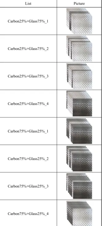
Fig. 11과 Fig. 12는 유리/탄소섬유 하이브리드 섬 유 적층 순서별 인장강도를 나타내었다. Fig. 11은 탄 소섬유 2ply와 유리섬유 6ply를 사용하여 적층 한 것 을 나타내고 있으며, Fig. 12는 탄소섬유 6ply와 유리 섬유 2ply를 사용하여 적층 한 것을 나타내었다.
실험 결과를 확인해 보면, 탄소섬유25%와 유리섬유 75%의 같은 함유량으로 적층을 하였을 때와 탄소섬유 75%와 유리섬유 25%로 각각 적층을 하였을 경우 모 두 상대적으로 강한 강도를 가진 탄소섬유가 중심으로 모여 있을수록 높은 인장강도 값을 나타내는 경향을 보 였다. 이는 강도가 강한 탄소섬유가 집적이 되어 있을
List Picture
Carbon25%+Glass75%_1
Carbon25%+Glass75%_2
Carbon25%+Glass75%_3
Carbon25%+Glass75%_4
Carbon75%+Glass25%_1
Carbon75%+Glass25%_2
Carbon75%+Glass25%_3
Carbon75%+Glass25%_4
Fig. 6 A comparison of glass/carbon fiber with stacking
sequenceFig. 7 Tensile testing machine(SHIMADZ UH- F500KNI)
Fig. 8 Fatigue testing machine(SAGINOMIYA)
1100 1000 900 800 700 600 500 400 300
1 2 3 4 5
Sample No.
1019.10
885.64
773.00
630.68
495.46
Tensile st rength (MPa)
1. Row carbon 2. Carbon75%+Glass25%
3. Carbon50%+Glass50%
4. Carbon25%+Glass75%
1100 1000 900 800 700 600 500 400 300
1 2 3 4 5
Sample No.
1019.10
885.64
773.00
630.68
495.46
Tensile st rength (MPa)
1. Row carbon 2. Carbon75%+Glass25%
3. Carbon50%+Glass50%
4. Carbon25%+Glass75%
Fig. 9 A comparison of tensile strength of glass/carbon
fiber with laminating contents1100 1000 900 800 700 600 500 400 300
Te ns il e s tren g th ( MPa )
1 2 3 4 5
Sample No.
1019.10
864.44
678.45
569.61 495.46 1. Row carbon 2. Carbon75%+Glass25%
3. Carbon50%+Glass50%
4. Carbon25%+Glass75%
5. Row Glass
Fig. 10 A comparison of tensile strength of glass/carbon
fiber with woven states수록 응력 전달에 유리함을 나타낸다고 볼 수 있다.
4.2 굽힘 시험 결과
유리/탄소섬유의 함유율, 적층 순서, 직조 방법을 달 리하여 굽힘 실험을 진행하였다. Fig 13은 유리섬유와 탄소섬유의 적층 수의 비율에 따른 굽힘 강도를 나타낸 것이다. 그리고 Fig. 14은 두 섬유의 함유량 차이를 보이는 하이브리드 섬유 직조 상태에 의한 굽힘 강도 특성을 조사해 보았다.
Fig. 15은 섬유의 비율이 같을 때 적층 방법과 직조 방법에 따라 강도의 차이가 어느 정도 나타나는지를 나 타내어 보았다.
실험 결과를 확인해 보면 인장 실험과 같은 경향을 나타낸다는 것을 볼 수가 있다. 인장 실험과 마찬가지 로 두 경우 모두 Row carbon 상태에서 높은 굽힘 강 도를 나타내다가, 유리섬유의 비율이 높아질수록 감소 하는 경향을 나타내었다.
Fig. 16와 Fig. 17은 유리/탄소섬유 하이브리드 섬 유 적층 순서별 굽힘 강도를 나타내었다. Fig. 16은 탄소섬유 2ply와 유리섬유 6ply를 사용하여 적층 한
것을 나타내고 있으며, Fig. 17은 탄소섬유 6ply와 유 리섬유 2ply를 사용하여 적층한 것을 나타내었다.
실험 결과를 확인해 보면, 인장시험 결과와 같은 경 향을 나타내는 것을 볼 수 있었다. 탄소섬유 25%와 유 리섬유 75%의 같은 함유량으로 적층을 하였을 때와 탄소섬유 75%와 유리섬유 25%로 각각 적층을 하였을 경우 모두 상대적으로 강한 강도를 가진 탄소섬유가 중 심으로 모여 있을수록 높은 굽힘 강도 값을 나타내는 경향을 보였다. 이는 인장강도 때와 마찬가지로 강도가
1100
1000
900
800
700
900
1 2 3 4
Sample No.
844.09
876.94 885.64
929.83
Ten s il e str ength (MPa)
1. Carbon75%+Glass25%_1 2. Carbon75%+Glass75%_2 3. Carbon75%+Glass25%_3 4. Carbon75%+Glass25%_4
Fig. 13 The tensile strength for stacking sequence of hy-
brid fiber reinforcements with carbon75%/glass 25%1 2 3 4
Sample No.
5 1100
1000 900 800 700
600 500 400 300
Ten s ile st reng th (MPa) 835.66
708.33 646.76
530.85
385.36 1. Row carbon 2. Carbon75%+Glass25%
3. Carbon50%+Glass50%
4. Carbon25%+Glass75%
5. Row Glass
Fig. 14 A comparison of flexural strength of glass/carbon
fiber with laminating contents1100 1000 900 800 700
600 500 400 300
Tensil e st re ngt h (M Pa)
1 2 3 4 5
Sample No.
1. Row carbon
2. W_Carbon75%+Glass25%
3. W_Carbon50%+Glass50%
4. W_Carbon25%+Glass75%
5. Row Glass 835.66
713.14
545.98 497.08
385.36
Fig. 15 A comparison of flexural strength of glass/carbon
fiber with woven states1. Carbon75%+Glass25%
2. W_Carbon75%+Glass25%
3. Carbon50%+Glass50%
4. W_Carbon50%+Glass50%
5. Carbon25%+Glass75%
6. W_Carbon25%+Glass75%
885.64 864.44
773.00 678.45
630.68 569.61 1100
1000 900 800 700
600 500 400
300
T ens il e s treng th (MPa)
1 2 3 4 5
Sample No.
6
Fig. 11 A comparison of tensile strength of glass/carbon
fiber with laminating contents and woven states1100 1000 900 800 700 600 500 400 300
Tensile st rengt h (MPa)
1 2 3 4
Sample No.
694.90 677.66
630.68
563.64 1. Carbon25%+Glass75%_1 2. Carbon25%+Glass75%_2 3. Carbon25%+Glass75%_3 4. Carbon25%+Glass75%_4
Fig. 12 The tensile strength for stacking sequence of hy-
brid fiber reinforcements with carbon25%/glass 75%강한 탄소섬유가 집적이 되어 있을수록 응력 전달에 유 리함을 나타낸다고 볼 수 있다.
4.3 피로 시험 결과
유리/탄소섬유 하이브리드 복합재의 적층 순서를 달 리하여 피로 강도 실험을 진행하였다. Fig. 18은 유리 섬유와 탄소섬유의 각 함유량에 따라 피로 시험을 진행 한 것이다.
경우에 따라 다르지만 보통의 무한 수명의 임계 사이 클은 10 6 으로 정하고 있다. 피로에 의한 파괴는 응력집 중 부위에서 소성변형이 생긴 이후 미세균열이 만들어 지고, 이 미세균열이 반복하중에 의해 진전이 되어 파 괴에 도달하는 것이 보통의 피로파괴의 경우이다. 이를 바탕으로 Fig 18을 보았을 때, 탄소섬유의 함유량이 높을수록 피로에 의한 파괴에 유리하다는 것을 알 수 있었고, 임계 사이클에서의 파로 강도가 높다는 것을 알아낼 수 있었다. 이는 탄소섬유의 고탄성율 특성에 의해 응력집중부위에서 발생하는 소성변형을 최소화 시 켜 미세균열에 의한 잔류응력에 유리한 작용을 했기 때 문으로 생각된다.
5. 결 론
본 논문에서는 기존 일반 소형보트에 많이 적용되고 있는 유리섬유 복합소재와 경주용 요트 등에 많이 적용 되고 있는 탄소섬유 복합소재와의 하이브리드 복합재의 성형 방법에 따른 기계적 강도특성을 평가하여 다음의 결론을 얻을 수 있었다.
1) 유리/탄소섬유 하이브리드 복합재에 있어서 탄소 섬유의 함량 비율에 따라 인장강도 값이 거의 선형적으 로 높아짐을 알 수 있다.
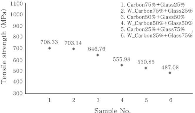
2) 유리/탄소섬유 라미네이트 하이브리드 복합재와 직조 하이브리드 복합재 인장강도 특성은 라미네이트 하이브리드 복합재가 직조 하이브리드 복합재 보다 약 8% 정도 더 높은 값을 나타낸다.
3) 유리/탄소섬유 하이브리드 섬유 패턴별 인장강도 특성은 물성이 높은 강화재 섬유가 한곳에 집중되어 있 는 패턴이 5% 정도 더 높은 값을 나타낸다.
4) 유리/탄소섬유 하이브리드 복합재에 있어서 굽힘
1100 1000 900 800 700
600 500 400 300
Te nsile st re ngth (MPa)
1 2 3 4 5
Sample No.
6 708.33 703.14
646.76
555.98 530.85 487.08 1. Carbon75%+Glass25%
2. W_Carbon75%+Glass25%
3. Carbon50%+Glass50%
4. W_Carbon50%+Glass50%
5. Carbon25%+Glass75%
6. W_Carbon25%+Glass75%
Fig. 16 A comparison of flexural strength of glass/carbon
fiber with laminating contents and woven states1. Carbon25%+Glass75%_1 2. Carbon25%+Glass75%_2 3. Carbon25%+Glass75%_3 4. Carbon25%+Glass75%_4
564.36 540.86 530.85
450.82
1 2 3 4
Sample No.
1100 1000 900 800 700 600 500 400 300
Tens ile s trengt h ( M Pa)
Fig. 17 The flexural strength for stacking sequence of hy-
brid fiber reinforcements with carbon25%/glass 75%1100 1000 900 800 700
600 500 400 300
Tens ile s tre ngth (MP a )
1 2 3 4
Sample No.
685.52 699.91 708.33 743.72 1. Carbon75%+Glass25%_1 2. Carbon75%+Glass25%_2 3. Carbon75%+Glass25%_3 4. Carbon75%+Glass25%_4
Fig. 18 The flexural strength for stacking sequence of hy-
brid fiber reinforcements with carbon75%/glass 25%1000
100
10
Stress range (MP a )
Carbon 100%
Carbon 75% + Glass 25%
Carbon 50% + Glass 50%
Carbon 25% + Glass 75%
Glass 100%
10
210
310
410
510
610
7Number of cycle
Fig. 19 A comparison of fatigue strength and life of glass/
carbon fiber with laminating contents
강도 특성도 인장강도 특성과 유사한 실험결과를 나타 낸다.
5) 유리/탄소섬유 하이브리드 복합재에 있어서 탄소 섬유의 함량 비율에 따른 피로강도는 탄소섬유의 비율 이 많은 복합재가 높은 것으로 나타난다.
6. 후 기
본 연구는 산업통상자원부 산업기술혁신사업의 ‘코어 재를 적용한 소형선박용 샌드위치 구조 섬유강화 복합 재 개발’사업으로 수행된 연구결과 중 일부임을 밝히며, 위 기관의 후원에 감사드립니다.
References
1. Byoung-Yoon Kang, Je-Hyoung Cho, Consideration for Structure and Fabrication Procedure of Alminum Boat,
Journal of KWJS, 22(3) (2004), 39-44 (in Korean)
2. Je-Hyoung Cho, Myung-Hyun Kim and Jun- Woong Choi, Application of Friction Stir Welding Processes for Aluminum alloy Boat, Journal of KWJS, 30(2) (2012), 31-36 (in Korean)
3. Jun-Woong Choi, Kyeung-Chae Park, Young-Bong Ko, Joining Ability and Mechanical Properties of Friction Stir Lap Welded A5052-H112 Alloy, Journal of KWJS, 28(1) (2010), 34-40 (in Korean)
4. Manders, P. W., M. G. Bader. The strength of hybrid glass/carbon fibre composites. Journal of Materials
Science 16(8) (1981), 2233-2245
5. Bunsell, A. R., B. Harris. Hybrid carbon and glass fibre composites. Composites 5(4) (1974), 157-164
6. Han, I. S., Kim, S. Y., Woo, S. K., Hong, K. S., Soe, D.
W. (2006). Characteristics of Glass/Carbon Fiber Hybrid Composite Using by VARTM. Journal of the Korean
Ceramic Socie ty, 43(10), 607-612
7. Dhakal, H. N., Zhang, Z. Y., Guthrie, R., MacMullen, J., Bennett, N. (2013). Development of flax/carbon fibre hy- brid composites for enhanced properties, Carbohydrate