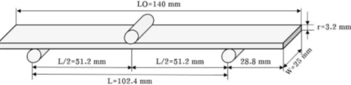
High Temperature Properties of Fiber Reinforced Composites under the Different Loading Conditions
5
0
0
전체 글
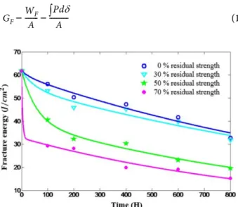
(2)
(3)
(4)
(5)
수치
관련 문서
The aim of this in vitro study was to evaluate the mechanical properties (bending strength and hardness) of seven different fiber reinforced composite posts, in relation to
ABSTRACT: In this study, the transverse mechanical properties of the unidirectional fiber reinforced composite modeled with fiber, matrix, and interphase is predicted
In this study, the effect of surface modification of jute fibers by alkali treatment has been investigated and short Jute fiber reinforced polypropylene matrix
The evaluation of the lateral load performance for larch glulam portal frames was carried out using glass fiber reinforced plastic (GFRP) as connector in two different systems:
According to Double Cantilever Beam theory, the stress intensity factor was 1.08 ∼1.38 for sheet glass fiber reinforced plastic reinforced laminated timber and 1.38 ∼1.86 for
Self-Healing Properties of Fiber-Reinforced Cement Composite (FRCC) Depending on Various Curing Conditions..
Abstract: In this paper, optimal designs of bicycle frame were studied for weight reduction of bicycle using carbon- fiber-reinforced plastic
In this study, the mechanical properties of injection-molded glass-fiber- reinforced polymer were assessed at a temperature of 85°C and the maximum
