*1 Received on December 9, 2011; accepted on March 24, 2012
*2 Department of Wood Science and Technology, Kyungpook National University, Daegu 702-701, Korea
*3 Department of Wood Science, University of British Columbia, Vancouver, B.C., V6T 1Z4, Canada
†
Corresponding author : Byung Dae Park (e-mail: [email protected])
Characterization of Electrospun Nanofibers of Cellulose Nanowhisker/Polyvinyl Alcohol Composites* 1
Mijung Cho*
2, Byung Dae Park*
2†, and John F. Kadla*
3ABSTRACT
Cellulose nanowhisker (CNW) isolated from hardwood bleached kraft pulp (HW-BKP) using sulfuric acid hydrolysis was suspended in polyvinyl alcohol (PVA) and electrospun into composites nanofibers.
Transmission electron microscopy (TEM) revealed the CNW to be rod-like, approximately of 16.1 ± 4.6 nm wide and 194 ± 61 nm long, providing an aspect ratio of about 12, with a particle size distribution range of 662.2 ± 301.2 nm. Uniform and high quality CNW/PVA composite nanofibers were successfully manufactured by the electrospinning method. As the CNW loading increases, the viscosity of CNW/PVA solutions shows a minimum at 1% CNW level which subsequently results in the smallest diameter (193 nm) of electrospun nanofibers. The average diameter of the nanofibers increased up to 284 nm with in- creasing CNW loading. These results suggest that the electrospinning method provides a great potential of manufacturing consistent and reliable nanofibers from CNW/PVA solution for the formation of scaffolds with potentials in future application.
Keywords : cellulose nanowhisker, electrospinning, nanofibers, polyvinyl alcohol, fiber diameter
1. INTRODUCTION
Cellulose has been used to reinforce polymer matrices in composites due to the environmental concern of other reinforcement material such as carbon fibers or glass fibers. It is the most abun- dant, renewable and biodegradable natural poly- mer on earth. In nature, cellulose exists as mi- crofibrils of varying dimensions. These are ag- gregates of parallel chains of cellulose macro- molecules, held together by hydrogen bonding (Hamad, 2002). The crystalline region of cellu-
lose contributes to the mechanical strength of cellulose. Thus, it has a high structural strength and stiffness. Because of these good mechanical properties, cellulose nanowhisker (CNW), have generated a great deal of interest as a source for nanometer size reinforcement (Eichhorn et al., 2010).
The first study on CNW was reported by Rånby in 1952, followed by Marchessault et al.
(1959). However, the use of nanocelluloses as a
reinforcement material in nanocomposites had
only started 15 years ago (Favier et al., 1995).
These studies demonstrated a small amount of tunicin whisker significantly enhanced the me- chanical property of synthetic latex. Such work played a prominent role in generating early ex- citement about the potential of using nanocom- posites. Therefore, in addition to its environ- mental friendliness, CNW can be used to fab- ricate new materials with remarkably improved mechanical and physical properties at lower vol- ume fraction than existing reinforcement materi- als such as glass fiber, carbon fiber and carbon nanotubes (CNT). Recently, Eichhorn et al. (2010) published a comprehensive review on current research activities on CNW based nanocompo- sites and their applications. It included CNW reinforced elastomers, interfacial micromechanics of CNW based nanocomposites, hydrogen bond- ing exploitation of CNW, shape memory nano- composites, or analysis of CNW dispersion etc.
There are several potential applications of CNW- based nanocomposites including as a filler for adhesives, transparent layer for electronic de- vices, semi-structural uses, CNW/DNA hybrid nanomaterials, CNW-based biofoams, etc.
Electrospinning is a very simple and effective method of producing nanofibers with a wide range of diameters (Huang et al., 2003). In this process, an electrical potential is applied be- tween a droplet of a polymer solution, or melt, held at the end of a capillary tube and a grounded target. When the applied electric field overcomes the surface tension of the droplet, a charged jet of polymer solution is ejected and is controlled by the electric field (Chronakis, 2005). Several factors can affect the electro- spinning process: a) solution properties such as viscosity, conductivity and surface tension, b) controlled variables like hydrostatic pressure in the capillary, electric potential at the tip, and the collection screen, and c) ambient parameters including temperature, humidity, and air veloc- ity in the electrospinning chamber (Doshi and
Reneker, 1995).
The number of applications and research fields that utilize electrospun polymer nano- fibers has been steadily increased. It is found in filtration systems and in medical prosthesis, mainly in grafts and vessels. Other targeted ap- plications include tissue templates, electromag- netic shielding, composite delimitation, and liq- uid crystal devices. It is worth noting that most of these applications are still within the labo- ratory settings and have yet to be commercial- ized (Haung et al., 2003).
Electrospun fibers produced from PVA have been widely studied over the past few years.
Recently, organic and inorganic based PVA hy- brid nanocomposite fabricated using electropin- ning method has attracted great interest. Jeong et al. (2007) studied PVA/multi-walled carbon nanotubes (MWCNT) nanofibers and found that the dispersivity and interfacial stress were pre- dominant factors affecting the tensile strength and thermal stability of the PVA/MWCNT nano- composites. Other studies generated fibers by electrospinning chitosan mixtures with PVA (Ch- arernsriwilaiwat et al., 2010; Li and Hsieh, 2006). Charernsriwilaiwat et al. (2010) con- cluded that the chitosan/PVA nanofiber may be suitable for use in drug delivery or tissue en- gineering applications because of its non-toxic and biodegradable property. However, very little work has been done to systematically examine electrospun CNW-based nanofibers. A recent study demonstrated that inclusion of CNW na- nofibers significantly improved the elastic mod- ulus of the electrospun nanofibers of CNW/
PVA composites, due to the strong interactions
of the hydrogen bonding network (Peresin et
al., 2010). In this work, we characterized nano-
fibers of CNW/PVA composites obtained by the
electrospinning method. In addition, we also
characterized CNW isolated from hardwood ble-
ached kraft pulp (HW-BKP) using sulfuric acid
hydrolysis.
2. MATERIALS and METHODS
2.1. Materials
Hardwood bleached kraft pulp (HW-BKP) was obtained from Moorim Paper Co. Ltd., Korea. Sulfuric acid (95%, DC chemical Co.
Ltd., Korea) and PVA (Mw 66,000) (Duksan Pure Chemical Co., Ltd., Korea) were used as received.
2.2. Preparation of CNW
CNWs were prepared from acid hydrolysis of HW-BKP using sulfuric acid (Revol et al., 1992; Kvien et al., 2005). Sulfuric acid was added to the pulp slurry (10 g of HW-BKP in 90 g of water) to obtain sulfuric acid concen- tration of 57%. And the acidified pulp slurry was allowed to react for 80 min at 45°C, fol- lowed by washing with de-ionized water for 20 min at 5,000 rpm (H-500, Hanil Centrifuge Co.
Ltd., Korea). The supernatant was removed and replaced with fresh deionized water, mixed and repeated until the supernatant is turbid. The sus- pension was then dialyzed with de-ionized wa- ter until the pH of the wash water became 4.
The collected supernatant was restored in the refrigerator (4°C) until used.
2.3. Characterization of CNW
Wet particle size analysis was conducted us- ing a laser diffraction particle size analyzer (N5/LS-13320, Beckman Coulter, USA) to meas- ure the approximate size of the CNW. During this analysis, a 0.5 wt% CNW solution was ex- posed to a 25 mV helium-neon laser light source for 200 s.
TEM (H-7600, Hitachi, Japan) observations
were performed at an accelerating voltage of 100 kV. The sample was diluted to a concen- tration of 0.5 wt% and sonicated for 20 min.
Three droplets of the CNW suspension were placed on a Cu-grid coated with a thin carbon film and allowed to dry at 70°C for 10 min. To enhance the contrast for TEM, the CNW were stained by allowing the grids to float in a 3 wt% solutions of uranyl acetate for 3 min. The grids were then dried at 70°C for 10 min. The particle dimensions were measured by counting individual CNW in the TEM micrographs using image analysis software (Ver. 8.5, IMT i-sol- ution Inc., Canada).
XRD (Rigaku D/Max-2500, Japan) was used to measure the crystallinity of the CNW isolated from the HW-BKP. Powdered samples were pre- pared by crushing the freeze-dried CNW. How- ever, the HW-BKP sample retained their origi- nal shape. The samples were analyzed at am- bient temperature using a CuK α-1 X-ray source with a wavelength ( λ) of 1.5418 Å. The angle of incidence was varied from 5° to 30° at a step of 0.02° and scanning rate of 6 °/min. The Segal method was used to calculate the crystallinity of the sample (Segal, 1959). The sample crystal- linity (X
CR) was determined by Eq. (1) using the height of the 200 peak (I
200, 2 θ = 22.7°) and the lowest height between the 200 and 110 peaks (I
AM, 2 θ = 18°). I
200represents both crystalline and amorphous material while I
AMrepresents only the amorphous material (Segal, 1959).
× (1)
Analysis using this equation assumes that the
amorphous material diffracts with the same in-
tensity at 2 θ of 18° and 22.7°, and that the
crystalline cellulose does not contribute to the
intensity at 18° (Thygesen et al., 2005).
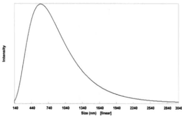
Fig. 1. Wet particle size analysis of CNW isolated from HW-BKP.
Fig. 2. TEM image of CNW isolated from HW-BKP at different magnifications: (a) × 10000, (b)
× 30000.
2.4. Preparation of PVA/CNW Solution
The CNW suspension was first concentrated by rotary evaporation (Rotovapor R110, BÜCHI, Switzerland) and mixed with a 10 wt% PVA solution at different CNW concentrations (1, 3, 5, and 7 wt%). The CNW/PVA suspensions were vigorously mechanically stirred at 80°C for 4 hours, followed by continued stirring until the solution reached room temperature. The final mixtures were sonicated for 10 min (Sonosma- sher, Jeio Tech, Korea) at 50% power output.
2.5. Electrospining of CNW/PVA Composite Nanofibers
Nanofibers from CNW/PVA solutions were prepared by horizontal electrospinning onto a rotating aluminum foil covered drum (30 cm wide) collector. The CNWs/PVA suspension was loaded into a 10 ㎖ syringe (1010TLL 81620, Hamilton Co., USA) with a metal needle (N722.
91022 m, Hamilton Co., USA) and a flow rate of 0.5 ㎖/h was applied and controlled by a sy- ringe pump (KDS101, KD Scientific Inc., Korea).
The applied voltage was 10 kV (CPS-60K02 VIT, Chungpa Emt Co., Ltd., Korea) and the needle tip to collector distance was 15 cm.
After electrospinning, the collected CNW/PVA composite nanofibers were stored in a desic- cator at room temperature.
The morphology of the CNW/PVA composite nanofibers was investigated using a field emis- sion scanning electron microscopy (FE-SEM, S- 4300, Hitachi, Japan) with an accelerating volt- age of 15 kV. A small piece of nanofiber mats was fixed on carbon tape and coated with Pt/
Au. The average diameter of the composite na- nofibers was obtained by measuring individual fibers in the FE-SEM micrographs using image analysis software (Ver. 8.5, IMT i-solution Inc., Canada).
3. RESULTS and DISCUSSION
Fig. 1 is the wet particle size distribution of CNWs obtained after sulfuric acid hydrolysis from HW-BKP. The size distribution of the CNW ranged from 140 nm to 3040 nm, which gives an average of 662.2 ± 301.2 nm, based on an analysis of more than 0.8 million particles.
This method measured both width and length of the CNWs by light scattering. This average val- ue was quite differed from the dimensions me- asured by TEM.
Fig. 2 is TEM images of the rod-like CNWs prepared by acid hydrolysis from HW-BKP.
Analysis of the TEM images revealed that the
isolated CNW had a width (d) of 16.1 ± 4.6 nm
and length (L) of 194 ± 61 nm, which corre-
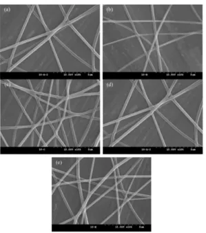
Fig. 3. FE-SEM images of electrospun nanofibers of CNW/PVA composites at different CNW concentrations. (a) 0%, (b) 1%, (c) 3%, (d) 5% and (e) 7%.
Cellulose nanowhisker content (wt%)
0 1 2 3 4 5 6 7
Fiber diameter (nm)
100 150 200 250 300 350 400