• 검색 결과가 없습니다.

Preparation and Characterization of Cellulose Nanofibril/Polyvinyl Alcohol Composite Nanofibers by Electrospinning

N/A
N/A
Protected

Academic year: 2021

Share "Preparation and Characterization of Cellulose Nanofibril/Polyvinyl Alcohol Composite Nanofibers by Electrospinning"

Copied!
11
0
0

로드 중.... (전체 텍스트 보기)

전체 글

(1)

Preparation and Characterization of Cellulose Nanofibril/Polyvinyl Alcohol Composite Nanofibers by Electrospinning 1

Byung-Dae Park

2†

⋅In Chul Um

3

⋅Sun-Young Lee

4

⋅Alain Dufresne

5

ABSTRACT

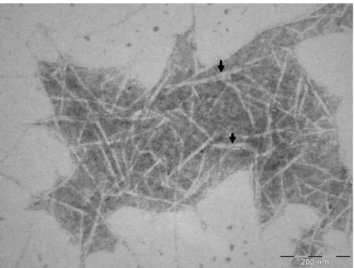
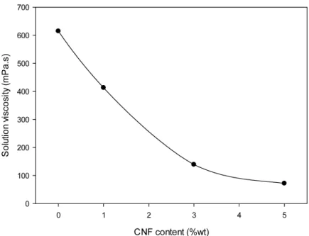
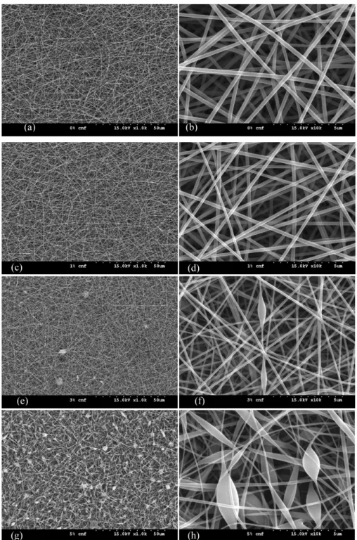
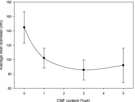
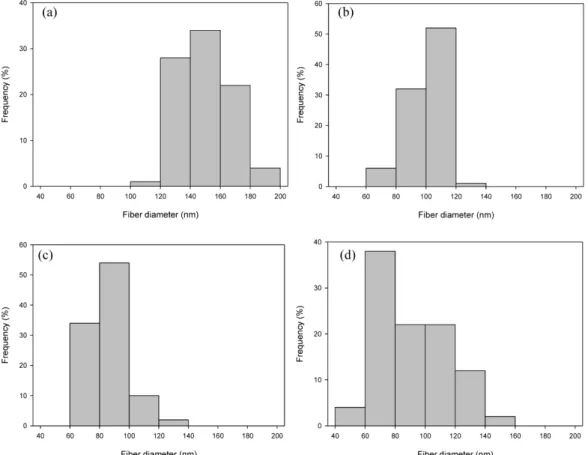
This work undertook to prepare nanofibers of cellulose nanofibrils (CNF)/polyvinyl alcohol (PVA) composite by elec- trospinning, and characterize the electrospun composite nanofibers. Different contents of CNFs isolated from hardwood bleached kraft pulp (HW-BKP) by 2,2,6,6-tetramethylpiperidine-1-oxy radical (TEMPO)-mediated oxidation were sus- pended in aqueous polyvinyl alcohol (PVA) solution, and then electrospun into CNF/PVA composite nanofibers. The morphology and dimension of CNFs were characterized by transmission electron microscopy (TEM), which revealed that CNFs were fibrillated form with the diameter of about 7.07 ± 0.99 nm. Morphology of the electrospun nanofiber observed by field-emission scanning electron microscopy (FE-SEM) showed that uniform CNF/PVA composite nano- fibers were manufactured at 1~3% CNF contents while many beads were observed at 5% CNF level. Both the viscosity of CNF/PVA solution and diameter of the electrospun nanofiber decreased with an increase in CNF content. The diam- eter and its distribution of the electrospun nanofibers helped explain the differences observed in their morphology. These results show that the electrospinning method was successful in preparing uniform CNF/PVA nanofibers, indicating a great potential for manufacturing consistent and reliable cellulose-based nanofibrils for scaffolds in future applications.

Keywords : Cellulose nanofibril, TEMPO, Polyvinyl alcohol, Electrospinning, Nanofiber, Diameter distribution

1. INTRODUCTION 1)

Among the natural biomaterials, cellulose is the most abundant, renewable and biodegra- dable polymer in the world. Cellulose fibrils consist of different hierarchical microstructures.

Parallel and long cellulose chains are stabilized

laterally by hydrogen bonds between hydroxyl groups, resulting in high structural strength and stiffness. The reported elastic modulus of native cellulose Ι crystal is 167.5 GPa (Tashiro &

Kobayashi, 1991) and that of tunic in whiskers is 143 GPa (Sturcováe et al., 2005). Because of its excellent properties, nanocellulose has gen-

1

Received December 27, 2013; accepted February 10, 2014

2

Department of Wood Science and Technology, Kyungpook National University, Daegu 702-701, Republic of Korea

3

Department of Bio-fibers and Materials Science, Kyungpook National University, Daegu 702-701, Republic of Korea

4

Division of Wood Processing, Korea Forest Research Institute, Seoul 130-712, Republic of Korea

5

Grenoble Institute of Technology (Grenoble INP), The International School of Paper, Print Media and Biomaterials (Pagora), CS10065, 38402 Saint Martin d¢Here, France

Corresponding author : Byung-Dae Park (e-mail: [email protected])

(2)

erated a great deal of interest as nanometer size reinforcement agent for a range of biocompo- sites.

Advances in nanotechnology have attracted much attention with regard to the utilization of cellulose nanomaterials, such as cellulose nano- whiskers (CNWs), cellulose nanofibrils (CNFs), or crystalline cellulose particles for preparing high performance nanocomposites because high- ly crystalline cellulose-based nanofibers are en- vironmentally compatible, and are endowed with several other unique and desirable features. Thus, cellulose-based nanomaterials are being increas- ingly employed for fabricating a wide variety of nanocomposites in combination with polymers, and the developments are benefitting from rapid advances in nanoscience and nanotechnologies (Azizi Samir et al., 2005; Eichhorn et al., 2010).

Preparation and characterization related to CNFs- based nanocomposites have been extensively studied in anticipation of many desirable prop- erty contributions from CNFs, such as high strength, high stiffness, biodegradability and lightweight.

In the last two decades, the 2,2,6,6-tetrame- thylpiperidine-1-oxyradical (TEMPO), a water- soluble, commercially available and stable ni- troxyl radical, has paved the way fora new field of conversion chemistry for efficient and se- lective conversion of alcoholic hydroxyl groups to aldehydes, ketones and carboxyl groups un- der mild conditions (de Nooy et al., 1995; de Nooy et al., 1996). Many related studies using TEMPO have been extensively carried out for CNFs from several wood pulps and cotton lint- ers in the last few years (Fukuzumi et al., 2009;

Saito et al., 2006; Saito et al., 2007; Isogai et al., 2011). CNFs prepared by TEMPO-mediated oxidation of native celluloses and successive

mechanical disintegration of the oxidized cellu- loses in water have also been extensively used for fabricating nanocomposites (Isogai et al., 2011).

According to the TEMPO-mediated oxidation, the C6 primary hydroxyls of cellulose are oxi- dized to C6 carboxylate groups in water at pH 10 ∼11. The oxidation process can be moni- tored from the pattern of aqueous NaOH con- sumption, which is continuously added to the reaction mixture to maintain the pH at 10 ∼11 during the oxidation. Thus the CNFs obtained by the TEMPO-oxidation have a high crystal- linity, mostly uniform widths (3 ∼4 nm), and large aspect ratios (> 50) compared with other nanocelluloses (Saito et al., 2006; Saito et al., 2007; Shinoda et al., 2012). Moreover, these CNFs can be completely dispersed at the individual nanofibril level in water by electrostatic repul- sion and/or osmotic effects due to anionically charged sodium carboxylate groups densely pre- sent on the surfaces (Saito & Isogai, 2004).

Electrospinning is a very simple, reprodu- cible, continuous and scalable one-step technol- ogy for the preparation of nanofibers with a controllable morphology from solutions of both natural and synthetic polymers (Bhardwaj &

Kundu, 2010). In this process, an electrical po-

tential is applied between a droplet of a poly-

mer solution, or melt, held at the end of a ca-

pillary tube and a grounded target. When the

applied electric field overcomes the surface ten-

sion of the droplet, a charged jet of polymer

solution is ejected and is controlled by the elec-

tric field (Chronakis, 2005). Several factors can

affect the electrospinning process: a) solution

properties such as viscosity, conductivity and

surface tension, b) controlled variables like hy-

drostatic pressure in the capillary, electric po-

(3)

tential at the tip, and the collection screen, and c) ambient parameters including temperature, humidity, and air velocity in the electrospinning chamber (Doshi & Reneker, 1995). Electrospun polymer nanofibers are increasingly finding a number of applications, such as filtration systems and in medical prosthesis, mainly in grafts and vessels. Other targeted applications include tis- sue templates, electromagnetic shielding, com- posite delimitation, and liquid crystal devices. It is worth noting that most of these applications are still within the laboratory settings and have yet to be commercialized (Haung et al., 2003).

Electrospun fibers produced from PVA have been widely studied over the last two decades (Zhang et al., 2005; Koski et al., 2004; Son et al., 2005; Rosic et al., 2013). Electrospinning has also been used for preparing cellulose-based nanofibers (Khil et al., 2005; Suwantong et al., 2007; Ahn et al., 2012). In recent years, in- clusion of CNWs isolated from native cellulose by sulfuric acid hydrolysis significantly im- proved the elastic modulus of the electrospun nanofibers of CNW/PVA composites, due to the strong interactions of the hydrogen bonding net- work (Peresin et al., 2010), and uniform and high quality nanofibers of CNW/PVA blend- swere successfully prepared by electrospinning method (Cho et al., 2012).

However, very little work has been done to prepare cellulose-based nanofibers using CNFs isolated by TEMPO oxidation method that pro- vides a good way of separating CNFs by com- bining with mechanical defibrillation. In this work, we prepared nanofibers of CNF/PVA blends by the electrospinning method, and charac- terized their morphology, diameter and diameter distribution by scanning electron microscopy.

2. Experimental

2.1. Materials

A sample of hardwood bleached kraft pulp (HW-BKP) was obtained from Moorim Paper Co. Ltd., Korea and stored in a humidity cham- ber at 25°C before use. TEMPO, sodium bro- mide (NaBr), sodium hypochlorite (NaOCl) sol- ution and other chemicals were purchased from Sigma-Aldrich and PVA (Mw 66,000) from Duksan Pure Chemical Co., Ltd., Korea, and all chemicals were used as received. PVA solution (10 wt%) with degrees of hydrolysis between 98 and 99% was first prepared at 80°C with stirring for 6 hours.

2.2. Isolation of CNFs

CNFs were isolated from cellulose pulp ac- cording to a modified procedure of the TEMPO- oxidation method (Saito et al., 2006). In brief, 2 g of kraft pulp sample was suspended in wa- ter (150 mL) containing TEMPO (0.025 g) and sodium bromide (0.25 g). The TEMPO-medi- ated oxidation of the cellulose slurry was ini- tiated by adding 5 mmol of 13% NaClO per gram of cellulose and carried out at room tem- perature under gentle agitation. The pH was maintained at 10.5 by adding 0.5 M NaOH.

When no more decrease in pH was observed,

the reaction was finished and pH was adjusted

to 7 by adding 0.5 M HCl. The TEMPO-oxi-

dized product was thoroughly washed with wa-

ter by filtration and physically fibrillated by ul-

tra-sonication with a sonicator (Sonosmasher,

Jeio Tech, Korea) for 20 min. The suspension

was then centrifuged at about 3,000 g in two to

three times for 30 minutes each. The super-

(4)

natant was decanted and collected as the CNF suspension. The yield of CNFs was calculated as a percentage of the initial weight of CNF suspension after drying in a drying oven at 105°C.

The final concentration of the CNFs was de- termined as 0.1% by weight/volume.

2.3. Preparation of CNF/PVA Solutions and Viscosity Measurement

The CNF suspension was first concentrated to 0.2% (w/v) by rotary evaporation (Rotovapor R110, BÜCHI, Switzerland) and then mixed with a 10 wt% PVA solution that had been ob- tained by vigorous mechanical stirring at 80°C for 4 hours, followed by continuous stirring un- til the solution reached room temperature. CNFs of different contents (0, 1, 3, and 5 wt%) were added into the PVA solution, and the final mix- tures were sonicated for 10 min (Sonosmasher, Jeio Tech, Korea) at 50% power output to get homogeneous suspensions. The viscosity of fi- nal mixtures at different CNF concentrations was measured by rheometry (MARS III, Hakke, Germany) with a cone and plate geometry at a shear rate of 10 s

-1

and 25°C. The radius and angle of the cone was 60 mm and 1°, respec- tively.

2.4. Electrospining of CNF/PVA Composite Blends

The electrospinning of CNF/PVA suspensions was performed with the electrospinning appara- tus (NNC-ESP200, NanoNC, Seoul, Korea). The CNF/PVA solutions were loaded into a plastic syringe using a 22 gauge stainless steel need leat the tip. The needle was electrified by a high voltage DC supply at an applied voltage of 16 kV. The tip to collector distance was 19

cm. After electrospinning, the collected CNF/

PVA composite nanofibers were stored in a desiccator at room temperature.

2.5. Characterization of CNFs

2.5.1. Morphology and Dimension of CNFs CNFs were examined and their dimensions measured with a transmission electron micro- scope (TEM) (H-7600, Hitachi, Japan), operat- ing at an acceleration voltage of 100 kV. The sample was diluted to a concentration of 0.01%

w/v. To examine the morphology of the CNFS, three droplets of the suspension were placed on Cu-grids coated with a thin carbon film and then allowed to dry at 30°C for 10 min. To en- hance the contrast in the TEM, the grids were floated on drops of 3% solution of uranyl ace- tate for 3 min and then dried at 70°C for 10 min. The particle dimensions were obtained by measuring 30 individual CNFs on TEM micro- graphs.

2.5.2. Morphology and Dimension of Electro- spun CNF/PVA Composite Nanofibers The morphology of the CNF/PVA composite nanofibers was investigated using a field emis- sion scanning electron microscope (FE-SEM, S-4300, Hitachi, Japan), operating at an accel- erating voltage of 15 kV. A small piece of nano- fiber mat was placed on carbon applied to stub and coated with Pt/Au. The average diameter of the composite nanofibers was obtained by mea- suring 50 individual fibers on FE-SEM micro- graphs using an image analysis software (Ver.

8.5, IMT i-solution Inc., Canada).

(5)

Fig. 1. TEM images of CNFs isolated by TEMPO- Oxidation from HW-BKP. (a) ×60,000, (b) ×100,000.

3. RESULTS AND DISCUSSION

3.1. CNFs’Morphology and Dimension and Viscosity of CNF/PVA Solution High magnification TEM images of the CNFs prepared by the TEMPO-oxidation method at different magnification levels are depicted in Fig. 1. While the majority of CNFs were fibril- lated, some were not fully fibrillated into nano- scale structure (arrows in Fig. 1). As determi- ned by TEM, the average diameter of fibrillated CNFS was about 7.07 ± 0.99 nm, a value that matches other measurements (Shinoda et al. 2012).

It was considered that the fibrillated CNFs would provide an efficient reinforcement with electro- spun nanofibers of CNF/PVA blends, while un- fibrillates or macrofibrils cause inconsistencies.

Prior to preparing nanofibers by electrospinning,

the viscosity of CNF/PVA solutions was de- termined as a function of CNF content. As ex- pected, the viscosity of the suspension decrea- sed with an increase in the CNF content (Fig.

2) because the amount of water in the CNF suspension increased with an increase in the CNF content in the CNF/PVA solution. It is expected that the viscosity of CNF/PVA sol- ution will have an influence on the quality of electrospun nanofibers.

3.2. Morphology and Dimension of Electro- spun CNF/PVA Nanofibers

Fig. 3 shows the morphology of the electro-

spun CNF/PVA composite nanofibers observed

by FE-SEM. Figs. 4 and 5 represent average

diameter and diameter distribution, respectively,

of CNF/PVA composite nanofibers as a func-

(6)

Fig. 2. The viscosity of CNF/PVA solution blends as a function of CNF content.

tion of CNF content. FE-SEM images from (a) to (h) in Fig. 3 display the morphology of the CNF/PVA composite nanofibers at different CNF contents (0 ∼5 wt%) after electrospinning.

The average diameter of the nanofibers of CNF/

PVA blends decreased as the CNF content in- creased (Fig. 4). In general, the fiber diameter increased with an increase in the viscosity (Gupta et al., 2005; Mit-uppatham, Mithitanakul, &

Supaphol, 2004), showing a good correlation between the diameter of electrospun fiber and solution viscosity. Other studies have also re- ported that a higher viscosity resulted in a larg- er fiber diameter in eletrospinning (Hamad, 2002;

Baumgarten, 1991; Doshi & Reneker, 1995).

Therefore, the decrease of fiber diameter with an increase in the CNF content is attributed to the viscosity of dope suspension.

Electrospun nanofibers prepared from the pure PVA solution showed very smooth and uniform nanofibers without any beads (Fig. 3,

a, b). The average diameter of the control nano- fibers was about 144.7 nm (Fig. 4). More than 84% of the nanofibers had diameters, ranging from 120 nm to 180 nm (Fig. 5, a).

When 1% CNFs was added into the PVA solution, the nanofibers of the CNF/PVA blend also showed fairly uniform and high quality nanofibers without any beads (Fig. 3, c and d).

The average diameter of the electrospun nano- fibers was about 102 nm (Fig. 4). No beads were observed for the electrospun nanofibers of 1% CNF/PVA blend, and 84% nanofibers had a diameter range of 80 ∼120 nm (Fig. 5, b).

As the CNF content increased to 3% and 5%, there were elliptical beads formed in the electrospun nanofibers. Measurements of the nanofiber diameter were done for normal nano- fibers with no elliptical beads. The number of elliptical beads were relatively small at 3%

CNF content. However, the majority of the

nanofibers were uniform, and the frequency of

(7)

Fig. 3. The FE-SEM images of electrospun nanofibers of CNW/PVA composites at different CNF loadings. (a)

∼(b) 0% CNF, (c)∼(d) 1% CNF, (e)∼ (f) 3% CNF, and (g)∼(h) 5% CNF.

(8)

Fig. 4. Average nanofiber diameters with standard deviation of CNFs/PVA composites as a function of CNF content.

beads was relatively low (Fig. 3, e and f). The average diameter of nanofibers was 85 nm, a valuelower than that for 1% CNF content.

About 88% of the electrospun nanofibers were in the range of 60 ∼80 nm (Fig. 5, c).

At the highest CNF content of 5%, the elec- trospun nanofibers contained many elliptical beads with a large variation in the nanofiber di- ameter (Fig. 3, g and h), and with twisted and irregular forms. There was also a relatively large deviation in the average diameter (92 nm) of the nanofibers (Fig. 4), which could be at- tributed to the presence of frequent beads. The diameter of nanofibers widely ranged from 40 nm to 160 nm which could explain the large deviation. About 60% nanofibers of 5% CNF/

PVA blend were greater than 80 nm in diame- ter (Fig. 5, d).

In electrospinning, an electric field is used to create a charged jet of polymer solution. As

this jet travels in air, the solvent evaporates leaving behind a charged fiber. So, the electro- spinning process is affected by many parame- ters (Doshi & Reneker, 1995). The observed beads in the electrospun nanofibers at 3% and 5% CNF content could be related to the applied conductivity and surface tension of the CNF/

PVA suspensions. As the charged jet travels in air, its diameter decreases due to the simulta- neous effect of stretching of the jet and evapo- ration of the solvent. Thus, it was difficult to form a stable jet as the CNF content increased.

So, a decrease in the viscosity and PVA con-

tent in the CNF/PVA suspension could result in

a reduced surface tension of the jet, and con-

sequent production of nanofibers with small di-

ameter as well as elliptical beads. Thus, a de-

crease in the viscosity of 3% and 5% CNF sol-

utions could be mainly responsible for the for-

mation of beaded fibers prepared by electro-

(9)

Fig. 5. Diameter distributions of the electrospun CNF/ PVA composites nanofiber as a function of CNF content.

(a) 0% CNF, (b) 1% CNF, (c) 3% CNF, and (d) 5% CNF.

spinning, which was compatible with the re- ported result (Fong, Chun, & Reneker, 1999).

In addition, unfibrillated CNFs (Fig. 1) might also influence the formation of unstable jet which could contribute to the formation of beads at high CNF contents, (3% and 5% levels).

4. CONCLUSION

This study reports the preparation of cellu- lose-based polymer nanofibers by electro- spinning, using CNFs isolated from native cel- lulose by TEMPO oxidation and aqueous PVA solution. Morphology and dimension of CNFs

were characterized by TEM, while the morphol- ogy of the nanofibers was observed by FE- SEM. In addition, the viscosity of CNF/PVA blend suspension was determined to explain variations in the diameter and its distribution of nanofibers. The following conclusions are drawn from the results obtained:

1) The CNFs as observed with TEM were mainly fibrillated structures in an aggregated form, with an average diameter of about 7.07 ±

0.99 nm. Unfibrillated fiber bundles were also

observed in CNFs, which impacted electrospun

nanofiber diameter and the formation of beads

at high CNF contents.

(10)

2) Electrospinning was successfully employed to prepare uniform nanofibers from CNF/PVA blends. The viscosity of CNF/PVA suspension and the diameter of nanofibers decreased as the CNF content increased. Nanofiber diameter dis- tribution also followed a similar trend.

3) These results indicate that electrospinning of CNF/PVA solutions can produce uniform nanofibers suitable for a variety of novel and high value applications.

ACKNOWLEDGEMENT

This work was supported by Kyungpook National University Research Fund, 2011.

REFERENCES

1. Ahn, Y., Lee, S.H., Kim, H.J., Yang, Y.H., Hong, J.H., Kim, Y.H., and Kim, H. 2012. Electro- spinning of lignocellulosic biomass using ionic liquid. Carbohydr. Polym. 88(1): 395 ∼398.

2. Azizi Samir, M.A.S.A., Alloin, F., and Dufresne, A. 2005. Review of recent research into cellulo- sic whiskers, their properties and their applica- tion in nanocomposite field. Biomacromolecules, 6: 612 ∼626.

3. Baumgarten, P.K. 1971. Electrostatic spinning of acrylic microfibers. J. Colloid. Interf. Sci. 36: 71

∼79.

4. de Nooy, A.E.J., Besemer, A.C., and van Bekkum, H. 1995. Highly selective nitroxyl radi- cal-mediated oxidation of primary alcohol groups in water-soluble glucans. Carbohydr. Res. 269:

89 ∼98.

5. de Nooy, A.E.J., Besemer, A.C., and van Bekkum, H. 1996.On the use of stable organic nitroxyl radicals for the oxidation of primary and secondary alcohols. Synth. 10: 1153 ∼1174.

6. Bhardwaj, N., and Kundu, S.C. 2010. Electro- spinning: a fascinating fiber fabrication technique.

Biotechnol. Adv. 28: 325 ∼347.

7. Cho, M., Park, B.D., and Kadla, J.F. 2012. Cha- racterization of Electrospun Nanofibers of Cellu- lose Nanowhisker/Polyvinyl Alcohol Composites.

J. Kor. Wood Sci. Technol. 40(2): 71 ∼77.

8. Chronakis, I.S. 2005. Novel nanocomposites and nanoceramics based on polymer nanofibers using electrospinning process-A review. J. Mater. Pro- cess. Technol. 167: 283 ∼293.

9. Doshi, J. and Reneker, D.H. 1995. Electrospinning process and applications of electrospun fibers. J.

Electrostat. 35: 151 ∼160.

10. Eichhorn, S.J., Dufresne. A., Aranguren, M., Marcovich, N.E., Capadona, J.R., Rowan, S.J., Weder, C., Thielemans, W., Roman, M., Ren- neckar, S., Gindl, W., Veigel, S., Keckes, J., Yano, H., Abe, K., Nogi, M., Nakagaito, A.N., Mangalam, A., Simonsen, J., Benight, A.S., Bismarck, A., Berglund, L.A., and Peijs, T. 2010.

Review: current international research into cellu- lose nanofibres and nanocomposites. J.Mater.

Sci. 45: 1 ∼33.

11. Fong H., Chun I., Reneker D.H. 1999. Beaded nanofibers formed during electrospinning, Poly- mer 40: 4585 ∼4592.

12. Fukuzumi, H., Saito, T., Iwata, T., Kumamoto, Y., and Isogai, A. 2009. Transparent and high gas barrier films of cellulose nanofibers prepared by TEMPO-mediated oxidation. Biomacromole- cules, 10(1): 162 ∼165.

13. Gupta, P., Elkins, C., Long, T.E., and Wilkes, G.L. 2005. Electrospinning of linear homopol- ymers of poly(methyl methacrylate): exploring relationships between fiber formation, viscosity, molecular weight and concentration in a good solvent. Polym. 46: 4799 ∼4810.

14. Hamad, W. 2002. Cellulosic Materials: Fibers, Networks and Composite, Kluwer Academic Publisher, Massachusetts.

15. Huang, Z.-M., Zhang, Y.-Z., Kotaki, M., and Ramakrishna, S. 2003. A review of polymer nano- fibers by electrospinning and their applications in nanocomposites. Compos. Sci. Technol. 63:

2223 ∼2253.

16. Isogai, A., Saito, T., and Fukuzumi, H. 2011.

(11)

TEMPO-oxidized cellulose nanofibers Nanoscale, 3: 71 ∼85.

17. Khil, M.S., Kim, H.Y., Kang, Y.S., Bang, H.J., and Lee, D.R. 2005. Preparation of electrospun oxidized cellulose mats and their in vitro degra- dation behavior. Macromol. Res. 13(1): 62 ∼67.

18. Koski, A., Yim, K., and Shivkumat, S. 2004.

Effect of molecular weight on fibrous PVA pro- duced by electrospinning. Mater. Lett. 58: 493 ∼ 497.

19. Mit-uppatham, C., Mithitanakul, M., and Supa- phol, P. 2004. Ultrafine electrospun polyamide-6 fibers: effect of solution conditions on morphol- ogy and average fiber diameter. Macromol. Chem.

Phys. 205: 2327 ∼2338.

20. Peresin, M.S., Habibi, Y., Zoppe, J.O., Pawlak, J.J., and Rojas, O.J. 2010. Nanofiber composites of polyvinyl alcohol and cellulose nanocrystals:

manufacture and characterization. Biomacromole- cules, 11: 674 ∼681.

21. Rosic, R., Pelipenko, J., Kristi, J., Kocbek, P., Bester-Rogac, M., and Baumgartner, S. 2013.

Physical characteristics of poly(vinyl alcohol) solutions in relation to electrosdpun nanofiber formation. Eur. Polym. J. 49: 290 ∼29.

22. Saito, T., andIsogai, A. 2004. TEMPO-mediated oxidation of native cellulose. The effect of oxi- dation conditions on chemical and crystal struc- tures of the water-insoluble fractions. Biomacro- molecules, 5: 1983 ∼1989.

23. Saito, T., Nishiyama, Y., Putaux, J.L., Vignon.

M., and Isogai, A. 2006. Homogeneous suspen-

sions of individualized microfibrils from TEMPO- catalyzed oxidation of native cellulose. Biomacro- molecules, 7(6): 1687 ∼1691.

24. Saito, T., Kimura, S., Nishiyama, Y., and Isogai, A. 2007. Cellulose nanofibers prepared by TEMPO-mediated oxidation of native cellulose.

Biomacromolecules, 8: 2485 ∼2491.

25. Shinoda, R., Saito, T., Okita, Y., and Isogai, A.

2012. Relationship between length and degree of polymerization of TEMPO-oxidized cellulose nano- fibrils. Biomacromolecules, 13: 842 ∼849.

26. Son, W.K., Youk, J.H., and Lee, T.S. 2005.

Effect of pH on electrospinning of poly(vinyl al- cohol). Mater. Lett. 59: 1571 ∼1575.

27. Sturcová, A., Davies, G.R., and Eichhorn, S.J.

2005. Elastic modulus and stress transfer proper- ties of tunicate cellulose whiskers. Biomacro- molecules, 6: 1055 ∼1061.

28. Suwantong, O., Opanasopit, P., Ruktanonchai, U., and Supaphol, P. 2007. Electrospun cellulose acetate fiber mats containing curcumin and re- lease characteristic of the herbal substance.

Polymer 48: 7546 ∼7557.

29. Tashiro, K., and Kobayashi, M. 1991. Theoreti- cal evaluation of three dimensional elastic con- stants of native and regenerated cellulose: role of hydrogen bonds. Polymer 32: 1516 ∼1526.

30. Zhang, C., Yuan, X., Wu, L., Han, Y., and Sheng, J. 2005. Study on morphology ofelec- trospun poly(vinyl alcohol) mats. Eur. Polym. J.

41(3): 423 ∼432.

수치

Fig. 1. TEM images of CNFs isolated by TEMPO- Oxidation from HW-BKP. (a) ×60,000, (b) ×100,000.
Fig. 2. The viscosity of CNF/PVA solution blends as a function of CNF content.
Fig. 3. The FE-SEM images of electrospun nanofibers of CNW/PVA composites at different CNF loadings
Fig. 4. Average nanofiber diameters with standard deviation of CNFs/PVA composites as a function of CNF  content.
+2

참조

관련 문서