CORROSION SCIENCE AND TECHNOLOGY, Vol.20, No.1(2021), pp.22~25 pISSN: 1598-6462 / eISSN: 2288-6524
[Research Paper] DOI: https://doi.org/10.14773/cst.2021.20.1.22
22
1. Introduction
The steam generator (SG) tubing of a nuclear power plant is one of the most vulnerable areas in the reactor coolant system pressure boundary. Alloy 600, a nick- el-chromium alloy, is widely used as a material for SG tubes because of its rich ductility, excellent corrosion re- sistance and strength at high temperatures. However, vari- ous kinds of flaws are occurring, and corrosive cracks are known to be the main cause of maintenance. In partic- ular, corrosive cracks are being detected in mill annealed alloy 600 (Alloy 600 MA) tubes, which are known to have weak corrosion resistance.
The H3, H4, H5, and H6 are four (4) identical nuclear power plants using Alloy 600 MA tubes. Since an ex- tensive number of SG tubes had been affected by stress corrosion cracking (SCC), the replacement to a SG made of thermally treated alloy 690 (Alloy 690 TT) tubes is in progress. However, in case of H6 SGs, despite being manufactured and operated in the same manner as the pre- ceding plants, it showed very excellent degradation
performance. In this study, the factors affecting SCC sus- ceptibility of Alloy 600 MA tubes were investigated through the analysis of the degradation characteristics of H6 SGs.
2. Degradation of Steam Generator Tubes
2.1 General Degradation Mechanism
The degradation mechanisms that experienced at steam generators show a great variety. SG tube degrada- tion can be due to corrosion mechanisms, fatigue, and mechanical wear. They have been very extensive, af- fecting both primary and secondary side, from which the secondary side degradation has been the main problem. In particular, various types of stress corrosion were experienced in the SGs using Alloy 600 MA tubes [1-3].
2.2 Tube Degradation Resistance
The SG tube is preferably a material having a sufficient strength and a high toughness and particularly excellent corrosion resistance in order to reduce the risk of rapid progress of defects or breakage of the tube. In the past, austenite stainless steels and Monel were also used as tub- ing materials, but most of them are made of Alloy 600
†Corresponding author: [email protected]
Kang Yong Seok: Principal Researcher, Lee Kuk Hee: Senior Researcher, Shin Dong Man: Principal Researcher
Factors Affecting Stress Corrosion Cracking Susceptibility of Alloy 600 MA Steam Generator Tubes
Kang Yong Seok†, Lee Kuk Hee, and Shin Dong Man
Korea Hydro & Nuclear Power Co., Ltd. CRI, Daejeon, Chungnam, 34101, Korea (Received November 30, 2020; Revised February 10, 2021; Accepted February 15, 2021)
In the past, Alloy 600 nickel-based alloys have been widely used in steam generators. However, most of them have been replaced by thermally treated alloy 690 tubes in recent years because mill annealed alloy 600 materials are known to be susceptible to stress corrosion cracking. Unlike this general perception, some steam generators using mill annealed alloy 600 tubes show excellent performance even though they are designed, manufactured, and operated in the same way. Therefore, various analyses were carried out to determine causes for the degradation of steam generators. Based on the general stress corrosion cracking mechanism, tube material susceptibility, residual stress, and sludge deposits of steam generators were compared to identify factors affecting stress corrosion cracking. It was found that mill annealed alloy 600 steam generator tubes showed higher resistance to stress corrosion cracking when the amount of sludge deposits on tube surface was smaller and residual stress generated during the fabrication was lower.
Keywords: Stress corrosion cracking, Alloy 600 mill annealed tubes, Residual stress, Sludge deposits, Steam generator
FACTORS AFFECTING STRESS CORROSION CRACKING SUSCEPTIBILITY OF ALLOY 600 MA STEAM GENERATOR TUBES
CORROSION SCIENCE AND TECHNOLOGY Vol.20, No.1, 2021 23 or Alloy 800 material. Alloy 600 series tubes can be clas- sified as Alloy 600 MA, 600 TT, 690 TT depending on metal composition and heat treatment method. Specially, Alloy 690 TT is the preferred material. It has been proven equal to or superior to Alloy 600 in all laboratory tests to date [3].
3. Steam Generator Degradation State
3.1 Design Features
The SGs of H3 through H6 are all designed and manu- factured identically. The U-tube bundle consists of 8,214, 19.05 mm diameter, 1.067 mm average wall thickness high-temperature mill annealed nickel-chromium alloy 600 (Alloy 600 HTMA) tubes. The tubes are supported by egg-crate type tube support plates made of stainless steel. The design hot-leg side temperature of those four reactors is 327 °C, but the operating hot-leg temperature
has been maintained about 323 °C.
3.2 Crack Initiation Sensitivity
Fig. 1 shows the comparison of the operating time until cracks are first detected in four units. The fastest case is 4.87 effective full power year (EFPY) at the H4 and the slowest case is 9.04 EFPY at H6. This means that the SCC incubation period of H6 is longer than that of previous plants with the same design.
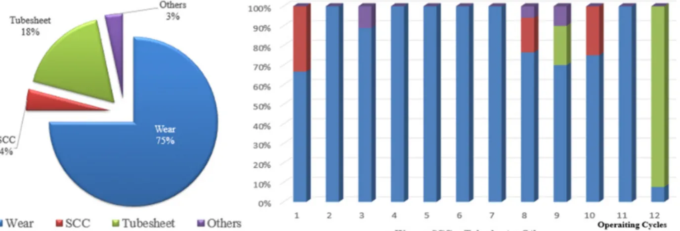
3.3 Evaluation of H6 Steam Generator Degradation Fig. 2 shows the percentage of total numbers of tube failures caused by each degradation mechanisms for the first in-service inspection through the 12th in-service in- spection of H6 SGs. Tube fretting wear and SCC were the main causes of the maintenance of the tubes. There was no cracks near the tube support plates. Compared with the state of preceding units, where the axial out diameter stress corrosion cracking (ODSCC) around the tube sup- port plates was detected on a large scale, it is unusual that H6 was not detected at all until the end of the 12th cycles.
During the 8th cycle, three cracks were detected at top of tube sheet, including two axial cracks and a circum- ferential crack. The axial cracks were very small with an effective depth of 31% through-wall and a circumferential crack with a percent degradation area (PDA) of 1.7%.
Then, one small axial crack was detected at top of tube sheet at the 10th cycles. Since then, no SCC has been detected.
4. Discussion
In general, it is known that the key factors that cause SCC are material susceptibility, residual stress and corro-
Fig. 2 Distribution of causes of tube plugging.
Fig. 1 Comparison of SCC Initiation Time.
KANG YONG SEOK, LEE KUK HEE, AND SHIN DONG MAN
24 CORROSION SCIENCE AND TECHNOLOGY Vol.20, No.1, 2021
sive environment. Therefore, based on these key factors, material selection of tubing, manufacturing residual stress, and corrosion environment of secondary side of the SGs were compared.
4.1 Material Susceptibility
The susceptibility of Alloy 600 MA materials to corro- sion resistance is well known. 600 MA is the alloy that has experienced most of the corrosion damage in pressur- ized water reactor SGs [4]. The microstructures of Alloy 600 MA tubes depend on the cooling rate from the final anneal temperature. All four units from H3 to H6 used Alloy 600 HTMA tubes.
4.2 Tube Residual Stress
The SG tube of the four plants were all manufactured according to the same technical specifications, but since the manufacturers are different, it is estimated that a small difference in the fabrication process has affected on SCC susceptibility. According to Chung et al. [4], it is revealed that the residual stress size in the tube affected ODSCC generation since the residual stress was higher than the operational stress caused by the pressure and temperature differential. Manufacturing residual stress is generated during the straightening rolling and then polishing process performed after the final mill annealing. The residual stress measured by the Slit method for the SG tubes of H6 is 112 MPa and 250 MPa for H3 & H4. Since the residual stress of H6 is relatively small, it is expected that stress corrosion cracking resistance of H6 is larger than that of H3 & H4.
4.3 Corrosive Environments
All cracks detected in H6 were ODSCC. Investigation for the root cause of the ODSCC about preceding plants, the cracks developed under a mildly alkaline environment formed inside occluded region, and specific micro- structures are the key elements controlling the suscepti- bility of Alloy 600 MA tubes to ODSCC [4].
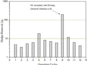
Therefore, the sediment distribution and removal amount of sludge, which is an impurities on the secondary side of the steam generator, were analyzed. H6 has carried out sludge lancing at every refueling outage to remove the sludge deposited on top of tube sheet. Fig. 3 shows the amount of sludge removal from top of tube sheet of H6 SGs compared by operation cycles. Excluding the 9th operating cycle where chemical cleaning was applied, the average amount of sludge removal per cycle is less than about 10 kg, which is very small compared to the preced- ing plants. Also, measurement of iron ingress through the feed water and the thickness of sludge profile as measured
by analyzing the eddy current inspection signal also con- sistently indicated there is less sludge deposit in H6 than H3 & H4.
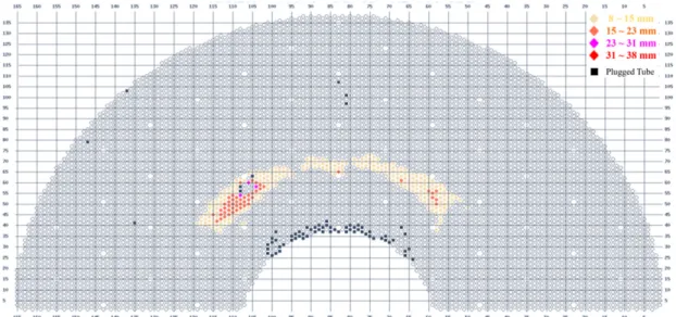
Fig. 4 shows the distribution profile of sludge on top of tube sheet of H6 SGs at the 12th in-service inspection.
It is only limitedly deposited in the heavy sludge deposi- tion region, and the deposition height is mostly low. From this, it is judged that limited transport of impurities into the H6 SGs was properly controlled.
For all units, the same high-temperature full-bundle chemical cleaning process was applied to alleviate ODSCC. In Fig. 5, which compares the amount of sludge removed by chemical cleaning in four units, the amount of H6 removed is the least. It can be seen that the corro- sive environment is the mildest because the amount of sludge of H6 is small. Also noteworthy here is that the timing of application of chemical cleaning of H6 was ear- lier than that of other units. As can be seen from Fig.
5, chemical cleaning in H6 was applied at the 9th in-serv- ice inspection (10.4 EFPY), but other units were applied later than this. In other words, it is estimated that because chemical cleaning was applied earlier than other units, the corrosive environment of tubes was relatively im- proved, resulting in a longer crack incubation period and a slower growth rate.
In terms of corrosive environment, the factor that caused H6 exhibit remarkable corrosion resistance is related to the deposition of sludge on the outer surface of the SG tubes. That is, the amount of sludge flowing into the sec- ondary side of SGs during normal operation was small, and because chemical cleaning was applied early, the cor- rosive environment was very mild. It is readily understood that lighter sludge deposit was contributed to the less de- velopment of ODSCC in H6.
Fig. 3 History of sludge lancing at top of tube sheet.
FACTORS AFFECTING STRESS CORROSION CRACKING SUSCEPTIBILITY OF ALLOY 600 MA STEAM GENERATOR TUBES
CORROSION SCIENCE AND TECHNOLOGY Vol.20, No.1, 2021 25
5. Conclusions
Alloy 600 MA material is well known for its suscepti- bility to stress corrosion cracking, but it shows very good performance in some steam generators. Based on the gen- eral corrosion cracking mechanism, factors affecting stress corrosion cracking were analyzed for steam generators of four identical plants using Alloy 600 MA tubes. It was
found that alloy 600 MA steam generator tubes showed higher resistance to stress corrosion cracking when the amount of sludge deposits on tube surface was smaller and residual stress generated during the fabrication was lower.
References
1. H. Cothron, Steam Generator Management Program:
Steam Generator Integrity Assessment Guidelines:
Revision 4, p. 6-5, EPRI Palo Alto, CA: 2016, 3002007571 (2016).
2. EPRI SGDD Website, https://sgdd.epri.com(2021).
3. IAEA-TECDOC-1668, Assessment and Management of Aging of Major Nuclear Power Plant Components Important to Safety: Steam Generators, pp. 29 - 30, (2011).
4. I. Peter and N. Paine, Steam Generator Reference Book Revision 1, pp. 4 - 5, EPRI, (1994).
5. Detection of ODSCC in SG tubes depending on the size of the crack and on the presence of sludge deposits, Aug.
2014, Nuclear Engineering and Technology, Vol 46 No.6 (2014).
6. K. Fruzzeti, Pressurized Water Reactor Secondary Water Chemistry Guidelines Revision 7, p. 2-3, EPRI Palo Alto, CA: 2009,101655 (2009).
Fig. 4 Distribution of sludge pile on top of tube sheet.
Fig. 5 Comparison of sludge removal by chemical cleaning.