http://dx.doi.org/10.5916/jkosme.2016.40.9.780 Original Paper
†Corresponding Author (ORCID: http://orcid.org/0000-0002-0322-8380): Division of Mechanical Engineering, Korea Maritime and Ocean University, 727, Taejong-ro, Yeongdo-gu, Busan 49112, Korea, E-mail: [email protected], Tel: 051-410-4298
1 R & D Center, DongHwa Entec, E-mail: [email protected] Tel: 051-970-0711
2 Department of Mechanical Engineering, Korea Maritime and Ocean University, E-mail: [email protected], Tel: 051-410-4972 3 Department of Mechanical Engineering, Korea Maritime and Ocean University, E-mail: [email protected], Tel: 051-410-4972 4 School of Mechanical Engineering, Pusan National University, E-mail: [email protected], Tel: 051-510-2440
LNG 연료 선박용 FGSS의 고압 기화기와 출입구 배관에 대한 구조 건전성 평가
김창수1 ․ 윤주환2 ․ 이창준3 ․ 하만영4 ․ 조종래†
(Received September 20, 2016; Revised October 24, 2016;Accepted November 1, 2016)
Evaluation of structural integrity of the HP vaporizer and pipes of LNG fuel gas supply system
Chang-Soo Kim1 ․ Joo-Hwan Yoon2 ․ Chang-Joon Lee3 ․ Man-Young Ha4 ․ Jong-Rae Cho†
요약: 선박의 연료로 이용되는 중유는 지구 온난화를 일으키는 유해가스를 배출한다. 이를 저감하기 위해 친환경선박으 로 표현되고 있는 녹색선박이 등장하게 되었고, 천연가스를 연료로 하는 액화천연가스(LNG) 연료 선박이 대표적인 사례 이다. 본 논문에서는 LNG 선박에 사용되는 극저온 환경에서 고압 하중을 받는 기화기와 출입구 배관의 구조 건전성을 ASME 코드에 따라 평가하고 실용화한 최초의 사례이다. 기화기와 배관은 유한요소법을 사용하여 구조해석을 수행하였 다. 기화기는 등가응력을 바탕으로 ASME Section VIII Division 2에 제시된 허용응력과 비교하여 건전성 평가를 수행하였 고, 배관은 성분별 응력을 조합하여 ASME B31.3에 제시된 허용응력과 비교 및 건전성 평가를 수행하였다. 각 하중에 대 한 구조물들의 응력 결과는 허용응력 범위 이내에 있으므로 구조적 건전성을 유지하는 것으로 평가되었다.
주제어: 액화천연가스(LNG), 연료공급시스템(FGSS), 기화기, 배관, 구조 건전성 평가
Abstract: Heavy oil used as ship propulsion has a serious issue regarding exhaust emission of global warming. Recently, among large-scale merchant ships are using LNG as green ships so called ech-ships. In this study, an vaporizer and pipes under cryogenic and high pressure load were considered to evaluate structural integrity according to codes. Structural analy- sis of the vaporizer and pipes was performed using the commercial code, ANSYS. Integrity evaluation of the vaporizer based on von Mises stress was performed in accordance with allowable stress specified in ASME Boiler & Pressure Vesssel Section VIII Division 2. To assess structural integrity of the pipes, stress components were combined and compared with ASME B31.3. The calculated stresses for all load cases are lower than allowable stresses, therefore the structural integrity of equipments are verified.
Keywords: Liquefied natural gas (LNG), Fuel gas supply system (FGSS), Vaporizer, Pipe, Structural integrity evaluation
1. 서 론 1.1 연구배경
최근 지구온난화로 인하여 국제적인 환경 규제가 강화 되고 있다. 선박 연료로 많이 이용되는 벙커C유외 중유에 서는 이산화탄소, 질소산화물, 황화합물 등의 유해가스가 배출되는데 이는 환경 오염의 원인이 된다[1][2]. 이러한 이 유로 국제해사기구에서는 선박의 유해가스 배출 기준을 강 화하고 있다. 따라서 친환경선박으로 표현 되고 있는 녹색 선박이 등장 하게 되었고, 천연가스를 연료로 사용하는 액 화천연가스(LNG) 연료 선박이 대안으로 판단되고 있다.
LNG 연료추진 시스템의 연료공급시스템(FGSS)에 대한 연
구는 개발 초기단계에서 실용화 단계로 이르고 있으며 지 속적인 연구가 필요하다.
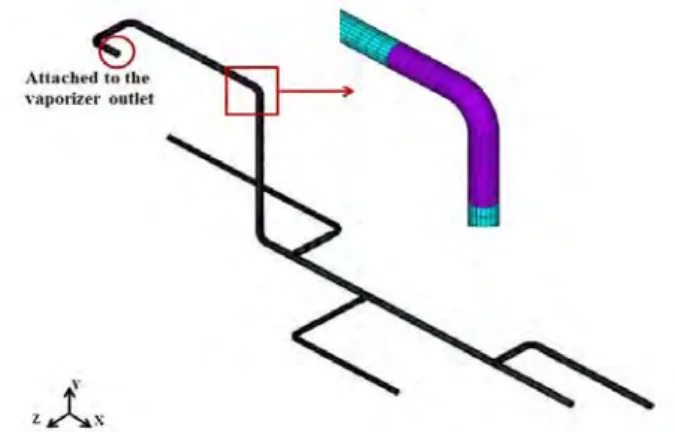
천연가스는 연료 탱크에서 극저온, 고압의 액화된 상태 로 저장되어 있고, 배관을 통해 기화기(vaporizer)로 전달된 다. 기화기에서 액화 상태의 천연가스는 기화 되고, 고압 상태로 엔진에 공급된다[3]. Figure 1은 FGSS의 모듈을 나 타내고 있다. 극저온, 고압의 환경에 있는 기화기와 배관을 안전하게 운전하기 위해서 기기의 건전성 평가가 필수적으 로 수행되어야 한다[4][5]. 특히 극저온에 따른 열응력과 배 관의 수축을 이완하기 위한 특수한 설계가 요구된다. Park et al. [6]은 슬라이딩 지지대를 제안하여 이중 배관에 적용 성을 평가하였다.
1.2 연구목적
본 논문에서는 선박의 원료로 사용되는 천연가스를 운반 하는 배관과 액화 상태의 천연가스를 기화시키는 기화기에 대하여 구조 건전성 평가를 수행하고자 한다. 이를 위해 실 제 운전 조건을 바탕으로 극저온, 고압 환경에서의 배관과 고압 환경에서의 기화기에 대해 구조해석을 수행하고, 각 구조물의 응력 결과를 바탕으로 ASME 코드[7][8]에 명시된 허용응력 기준과 비교하여 건전성 여부를 판단하였다.
2. 유한요소해석 2.1 유한요소모델
Figure 1: D-dimensional model of a FGSS module
기화기는 FGSS에서 액체 LNG를 기체로 바꾸는 셸-튜브 (shell-tube) 열교환기로, 사양은 길이 2 m 중량은 약 5000 kg 이며 420 bar에서 운전한다. 기화기와 배관의 구조 건전성 평가 기준은 ASME 코드를 바탕으로 진행하지만, 기화기와 배관은 ASME 코드에서 평가 방법이 서로 다르고 연결점을 기준으로 분리가 가능하여 따로 모델링을 진행하였다.
2.1.1 기화기의 유한요소모델
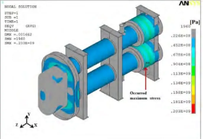
본 해석에서 사용된 기화기는 고압의 환경에서 사용하기 에 적합한 셸 -튜브 유형의 열교환기이다. 기화기의 최외각 부인 셸 구간과 기화기의 지지대는 구조물의 크기에 비해 상대적으로 얇은 두께를 갖기 때문에 셸 요소를 사용하였 고, 배관이 접해있는 채널 구간에는 솔리드 요소를 사용하 여 Figure 2와 같이 모델링하였다.
Figure 2: Finite element model of the vaporizer
2.1.2 배관의 유한요소모델
배관은 기화기의 입/출구를 기준으로 하여 두 구간으로 나누고 파이프 요소를 사용하여 모델링하였다. Figure 3과 Figure 4는 각각 입구 및 출구에 연결된 배관의 유한요소 모델이다. 각 구간의 배관 규격은 Table 1과 같다.
Figure 3: Finite element model of inlet pipe for the vaporizer
Figure 4: Finite element model of outlet pipe for the vaporizer
Table 1: Dimensions of pipes (SUS316) Size Outer
diameter[mm]
Thickness [mm]
Vaporizer inlet pipe
1.0" Sch 40 33.40 3.38 1.25" Sch 160 42.16 6.35 2.0" Sch XXS 60.33 11.07 Vaporizer
outlet pipe
1.0" Sch 40 33.40 3.38 1.0" Sch 160 33.40 6.35 1.25" Sch 160 42.16 6.35
2.2 재료 물성치
기화기와 배관의 재질은 극저온, 고압의 환경에 사용하기 적절한 오스테나이트계의 스테인리스강을 사용하였다[3].
Table 2와 Table 3은 각각 기화기와 배관의 온도에 따른 물성 치를 나타내고 있다. 각 물성치는 ASME 코드에서 제시한 값 을 사용하였다[9].
Table 2: Material properties of the vaporizer
-165 [℃] 100 [℃]
Young's modulus [GPa] 206.7 189 Density [kg/m3] 7750 7750
Poisson's ratio 0.3 0.3 Allowable stress [MPa] 115 115
Table 3: Material properties of inlet and outlet pipes -200 [℃] -125 [℃] 45 [℃]
Young's modulus [GPa] 209 204 195 Density [kg/m3] 7750 7750 7750
Poisson's ratio 0.3 0.3 0.3 Thermal expansion [/℃] 4.8e-6 8.6e-6 16.2e-6
Allowable stress[ MPa] 115 115 115
2.3 경계 및 하중조건
2.3.1 기화기의 경계 및 하중조건
기화기는 3개 지지대의 밑판(base plate)에 볼트 체결하여 지면과 고정된다. 이를 바탕으로 밑판의 볼트 체결 부위에 구 속 조건을 적용하였고, 기화기 자중을 고려하여 밑판이 지면 과 완전하게 맞닿는 것으로 가정하여 밑판의 면 전체에 수직 방향으로 구속하였다. Figure 5는 기화기에 적용한 구속조건 과 압력 하중을 나타낸 것이다. Table 4는 기화기의 입구 및 출구에 적용된 노즐 하중 조건이다.
Figure 5: Boundary and pressure condition of the vaporizer
Table 4: Nozzle loads conditions Fx
[N]
Fy [N]
Fz [N]
Mx [N․m]
My [N․m]
Mz [N․m]
Inlet of
vaporizer 33 33 33 254 254 254 Outlet of
vaporizer 22 22 22 169 169 169
2.3.2 배관의 경계 및 하중조건
기화기에 연결된 배관은 슬라이딩 클램프를 사용하여 지 지되므로 배관의 길이방향을 제외한 두 방향을 구속하였고, 기화기와 연결된 배관 끝단은 플랜지에 의해 기화기와 완전
하게 고정되어 있다고 가정하여 회전방향을 포함한 모든 방 향을 구속하였다. 그리고 여러 종류의 밸브는 자중을 고려하 였으며 배관의 수직 지지부도 고려하였다. Figure 6과 Figure 7은 각각 기화기의 입구 배관과 출구 배관에 연결된 구속 조 건을 나타낸 것이다.
Figure 6: Boundary conditions of inlet pipe for the vaporizer
Figure 7: Boundary conditions of outlet pipe for the vaporizer
각 배관의 경우 고압 상태의 천연가스가 이동하기 때문에 305 bar의 압력 하중을 적용하였다. 온도 조건의 경우 기화기의 입구 배관은 극저온상태의 액화된 천연가스가 이동하기 때문에 -155℃의 온도 조건을 적용하였고, 기화기의 출구 배관은 기화된 천연가스가 이동하기 때문에 45℃의 온도 조건을 적용하였다.
추가적으로 배관의 자중을 고려하여 중력 가속도를 적용하였다.
3. 구조해석 결과 및 평가 3.1 기화기의 해석결과
기화기의 구조해석 결과는 ASME Section VIII Division2의 평가기준에 따라 등가응력(von Mises stress)을 사용하였다.
Figure 8은 기화기의 전체적인 응력분포를 나타낸 것이다.
Figure 8: von Mises stress distribution at the vaporizer
기화기의 건전성 평가는 전체적인 등가응력 결과를 바탕 으로 수행하는 것이 아니라 구조물의 주요 부위에 대하여 ASME 코드를 바탕으로 수행한다. 이에 따라서 기화기의 관 심부인 셸, 셸 덮개, 채널 덮개, 튜브시트, 지지대로 나누어서 각 부품의 응력 결과와 ASME 코드의 기준을 비교하여 건전 성 평가를 진행하였다.
3.2 배관의 해석결과
Figure 9: Von Mises stress distribution at inlet pipe for the vaporizer under pressure load
Figure 10: Von Mises stress distribution at outlet pipe for the vaporizer under pressure load
Figure 11: Von Mises stress distribution at inlet pipe for the vaporizer under thermal load
Figure 12: Von Mises stress distribution at outlet pipe for the vaporizer under thermal load
배관의 구조해석 결과는 기화기와 동일하게 등가응력을 이용하여 도출하였다. Figure 9 ~ 12은 압력 및 온도하중에 의해서 발생한 응력 분포를 나타낸 것이다.
압력하중과 온도하중에 의해서 발생한 각각의 최대 응력 은 Figure 9 ~ 12에 나타낸 것처럼 곡관부위에서 발생하였다.
배관의 건전성 평가는 ASME B31.3이라는 배관용 코드를 적 용하여 수행할 것이다.
3.3 ASME code 평가기준 3.3.1 기화기의 평가기준
기화기의 건전성 평가는 다음과 같이 ASME Section VIII Division 2에 명시된 기준에 따른다.
≤ (1)
≤ (2)
≤ (3)
은 구조물의 넓은 범위에 걸쳐 발생하는 막응력, 는 굽힘 응력, 은 구조물의 기하학적 불연속부에 생기는 막응 력 이에 해당한다. 기하학적 불연속부는 주로 구조물의 끝단
또는 구조물이 서로 연결된 위치를 말한다[5].
3.3.2 배관의 평가기준
배관의 건전성 평가는 다음과 같이 ASME B31.3 코드를 따르며 압력하중에 의해서 발생한 응력 결과와 온도하중에 의해서 발생한 응력 결과를 각각 평가한다.
(4)
(5)
식 (4)는 압력하중에 의해서 발생한 응력 계산 수식을,
식 (5)은 온도하중에 의해서 발생한 응력 계산 수식을
나타낸 것이다. 여기서 는 축력에 의한 응력, 는 굽힘 모멘트에 의한 응력, 는 비틀림에 의한 전단응 력을 의미한다. 의 허용응력은 1.0S로 정의하고 의 허용응력은 1.5S로 정의한다. S는 재료의 허용응력을 의 미한다[6][7][8].
3.4 건전성 평가
3.4.1 기화기의 건전성 평가
Table 6은 기화기의 각 부품들에 대한 응력 결과와 ASME 코드에서 제시한 허용응력을 나타낸 것이다. 기화기 의 구조해석 수행 결과 모두 허용응력 범위 이내에 있으 므로 구조적 건전성을 유지할 수 있다.
Table 6: Summary of stress analysis results at the vaporizer component Stress
classification
Stress value [MPa]
Limited stress [MPa]
Channel cover Pm 47 115
Pm+Pb 104 172.5
Tubesheet Pm 50.8 115
Pm+Pb 75.6 172.5
Shell cover Pm 27.4 115
Pm+Pb 152 172.5
Support Pm 59.6 115
Pm+Pb 59.6 172.5
shell near nozzle
Pl 38 172.5
Pl+Q 100 345
3.4.2 배관의 건전성 평가
Table 7과 Table 8은 압력 및 온도 하중에 의해서 발생한 응력 결과와 ASME 코드에서 제시한 허용응력을 나타낸 것이다. 온도하중에 의하여 발생한 응력의 경우 압력하중 에 의하여 발생한 응력과 다르게 축력에 의한 응력은 제외 된다. 또한 배관의 경우 피로하중은 고려하지 않는다.
기화기의 입구와 출구 배관에 대하여 압력 및 온도 해석 결과 모두 허용응력 범위 이내에 있으므로 구조적 건전성 을 유지 할 수 있다.
Table 7: Summary of stress analysis results at pipe under pressure load
Component Ssa
[MPa]
Ssb
[MPa]
Sst
[MPa]
SL
[MPa]
Limited stress [MPa]
Inlet Pipe 37.0 53.5 0.9 90.6 115 Outlet Pipe 36.8 11.0 8.48 65.1 115
Table 8: Summary of stress analysis results at pipe under thermal load
Component Ssb
[MPa]
Sst
[MPa]
SL
[MPa]
Limited stress [MPa]
Inlet Pipe 120.7 0.3 121 172.5 Outlet Pipe 86.3 37.5 114.4 172.5
4. 결 론
본 논문에서는 LNG 선박에서 사용되는 고압 극저온 환 경에서의 기화기와 배관에 대하여 구조 건전성 평가를 수 행하기 위하여 구조해석을 실시하였다. 구조해석 수행 후, 해석 결과를 ASME 코드와 비교하여 구조 건전성 평가를 수행하였다. 따라서 본 논문은 FGSS에서 기화기와 배관의 해석 모델과 건전성 평가방법을 처음으로 제시하여 실용화 하였으며 다음과 같은 결론을 얻었다.
(1) 압력 및 노즐 하중 조건에서 발생하는 기화기의 응력 결과가 ASME 코드에 제시된 허용 응력 범위 이내에 있으므로 구조적 건전성을 유지할 수 있다.
(2) 배관의 구조해석 결과, 압력 하중보다 온도 차이에 의 해서 발생하는 응력이 더 크게 발생한다는 것을 확인 하였다.
(3) 압력 및 온도 하중에서 발생하는 배관의 응력 결과가 ASME 코드에서 제시된 허용 응력 범위 이내에 있으므 로 구조적 건전성을 유지 할 수 있다.
References
[1] Y. C. Park, H. S. Park and S. P. Kim, “Analysis method on structural safety evaluation of Butterfly valve of piping for LNG carrier,” Journal of the Korea Society of Manufacturing Process Engineers, vol. 7, no. 4, pp. 76-81, 2008.
[2] Y. H. Lee, Y. T. Kim, and H. K. Kang, “An analysis on the characteristics of regasfication system for gas fuelled ship depending on the mixing ratio of eglycol and water,” Journal of the Korean Society of Marine Engineering, vol. 38, no. 7, pp. 799-805, 2014.
[3] D. C. Lee, H. Afrianto, H. S. Chung, and H. M.
Jeong, “Numerical analysis of LNG vaporzier heat transfer characteristic in LNG fuel ship”, Journal of
the Korean Society of Marine Engineering, vol. 37, no. 1, pp. 22-28, 2013.
[4] Y. G. Kim, S. B. Choi, J. B. Choi, H. C. Lee, and I.
J. Hwang, “A study on the structural behavior of pipes operating under cryogenic environment,” The Society of Air-Conditional and Refrigerating Engineering, Proceeding of Winter Conference, pp.
47-51, 2009.
[5] S. K. Min and M. J. Choi, “A study on design cri- teria of piping system in pertochemical plant,” Journal of the Korean Society for Precision Engineering, vol.
19, no. 6, pp. 192-199, 2002.
[6] S. B. Park, M. J. Sim, M. S. Kim, J. H. Kim, and J.
M. Lee, “A study of thermo-mechanical analysis for the design oh high pressure piping system for natural gas fuel vessel,” Journal of the Korean Society of Marine Engineering, vol. 39, no. 4, pp. 425-431, 2015.
[7] ASME, Appenix S : Piping system stress analysis ex- amples, Process Piping, ASME Code for Pressure Piping, B31.3-2006.
[8] ASME, ASME Boiler and Pressure Vessel Code, Section VIII Div. 2, 2013.
[9] ASME, ASME Boiler and Pressure Vessel Code, Section II Part D Properties (Metric), 2013.
![Table 8: Summary of stress analysis results at pipe under thermal load Component S sb [MPa] S st [MPa] S L [MPa] Limited stress [MPa] Inlet Pipe 120.7 0.3 121 172.5 Outlet Pipe 86.3 37.5 114.4 172.5 4](https://thumb-ap.123doks.com/thumbv2/123dokinfo/4824189.281143/5.892.83.432.706.921/table-summary-analysis-results-thermal-component-limited-outlet.webp)
