1. Introduction
1)The drastic change from pervious to impervious surfaces due to urbanization has led to a rapid increase in direct runoff which impacts the natural hydrologic cycle and affects the water quality and quantity of the water sources to which it is released. With increasing urbanization, there has been
†To whom correspondence should be addressed.
Department of Environmental Engineering, Hanseo University E-mail: [email protected]
a quantifiable decrease in the amount of area available for stormwater infiltration (Kim et al., 2016; Shuster et al., 2005). As a result, elevated amounts of stormwater runoff flow over impervious areas and carries sediments, metals, and other non-point source (NPS) pollutants which do not only cause adverse effects in the ecological environment of the receiving water bodies but can also potentially induce downstream flooding, erosion, and sedimentation (Liu et al., 2012; D’Ambrosio et al., 2014).
As a solution, low impact development (LID) technologies and practices have been adapted to mimic natural processes
Performance Assessment and Design Evaluation of Bioretention Planter Boxes Treating Urban Stormwater Runoff
Heidi B. Guerra・Kisoo Park・Youngchul Kim†
Department of Environmental Engineering, Hanseo University
도심지역 강우유출수 처리목적 식물재배화분의 성능 및 설계인자 분석
게라 하이디・박기수・김영철†
한서대학교 환경공학과
(Received : 07 December 2017, Revised: 01 February 2018, Accepted: 01 February 2018)
Abstract
Two planter boxes were monitored during their initial year of operation to be able to assess their stormwater runoff and pollutant reduction capabilities and investigate on the design factors affecting their performance. One of the planter boxes provided 85-100% runoff volume reduction for rainfall less than 15 mm and rainfall intensities lower than 5 mm/hr. This reduced to 50-64% during higher rainfall intensities and depths of up to 50 mm. Suspended solids, organics, nutrients, and heavy metals were satisfactorily removed at a range of 40-95%. The other planter box, however, did not produce outflow in all the events and allowed total capture of stormwater. The uncertainty regarding the fate of the runoff in that case required an investigation of the planter box’s actual drainage and underground conditions which was deemed outside the scope of the study. Nonetheless, several design improvements and retrofits were suggested based on the provisions of current design guidelines to ensure that the hydraulic and water quality goals are achieved without potential damage to nearby structures. Moreover, continuous monitoring data is required to provide more accurate design evaluation and can serve as a guide in the construction of similar facilities in the future.
Key words : design evaluation; low impact development; planter box; stormwater management; urban runoff
요 약
소규모 바이오 리텐션과 유사한 기능을 수행하는 식물재배화분은 유출저감과 함께 비점오염을 저감할 수 있다는 측면에서 도시지역에 유망한 LID 시설이다. 본 연구에서는 2개소의 실증 식물재배화분을 모니터링 평가하였다. 이 시설을 통하여 1개소의 시설에서는 강우량이 15mm 이하일 경우 85-100% 유출저감을 달성하였으며 강우량 50mm에서는 50-64%의 유출저감 을 나타내었다. 이와 같은 조건에서 TSS와 유기물질, 영양소 및 중금속의 저감효율은 40-95% 이었다. 이와 반면에 다른 시설에서는 동일한 강우조건에서 강우유출수 전량이 포착되어 유출발생이 일어나지 않았는데 식물재배화분 통과 후 배수 및 지하여건에 대한 정밀한 재평가가 필요한 것으로 나타났다. 이와 같은 상황이 주변 지하수나 지하구조물에 위해를 가할 수 있으므로 식물재배화분의 설계 및 시공시 투수속도에 면밀한 검토가 필요하며 투수계수가 지나치게 큰 지역에는 토목섬유 포설이나 차수 배리어와 같은 라이닝 시공을 실시해야 한다.
핵심용어 : 도시지역 강우유출수, 비점오염, 식물재배화분, 저영향개발, 투수계수
by recreating natural landscape features that allows temporary storage as well as infiltration and evapotranspiration of stormwater in order to minimize effective imperviousness and protect water quality and associated aquatic habitat (USEPA, 2017). One of these LID systems is the stormwater planter or planter box which has been widely used due to its ability to reduce runoff volume and attenuate peak flows while also reducing NPS pollution in confined urban environments. It can be considered as a small bioretention facility because it functions similarly and contains a vegetated area which collects and filters stormwater through layers of soil and plant roots. While limited treatment performance and design information on planter boxes is currently available in Korea, several case studies in the United States provide satisfactory performance data on these systems.
Moreover, long term hydrologic performance of bioretention technologies has also been a focus of recent studies such as that conducted by Li and Lam (2015) where the annual runoff retention ratio were estimated using watershed area ratio and hydraulic conductivity of the soil media.
Planter boxes are typically designed as either infiltration or flow-through (filtration) planters. Infiltration planter, as the name implies, allows treated stormwater to infiltrate into the sub-soil as groundwater. This type are generally required to have a 3-10 m setback from establishments to avoid structural damage from lateral flows. If site conditions are not appropriate for infiltration or if the planter box is designed to be placed next to buildings, flow-through planters are employed. This type is completely contained within an impermeable barrier and installed with an underdrain that discharges stormwater into an existing drainage system.
While several design guidelines for LID systems are currently available, site specific conditions such as rainfall patterns and subsoil properties must be taken into consideration to be able to determine whether the design is effective. Also, sizing techniques that have been proven adequate in one region may not be as effective when applied in another region with different hydrologic and topographic conditions (Gallo et al., 2012). Other design considerations include physical constraints such as media type, depth to groundwater, complete drawdown or emptying time, and setbacks from nearby establishments for structural safety.
Thus, gathering and analyzing sufficient data from field monitoring is essential in providing information for future design reference and recommendations.
In this study, two recently constructed planter boxes are monitored to be able to have knowledge on its hydraulic performance and water treatment capability during the initial year of operation. Runoff volume retention and pollutant
removal were determined and statistical analysis were conducted to determine significant differences in performance.
Moreover, design recommendations were provided based on the observed data and comparison between the as built design characteristics and some available design guidelines.
2. Materials and Methods
2.1 Site description and design characteristics Rectangular planter boxes were constructed together with other types of LID systems in Jeonju City, South Korea, for the purpose of reducing NPS pollution in the area. Two planter boxes, PB1 and PB2, located approximately 430 m apart alongside an urban asphalt road were chosen for this study.
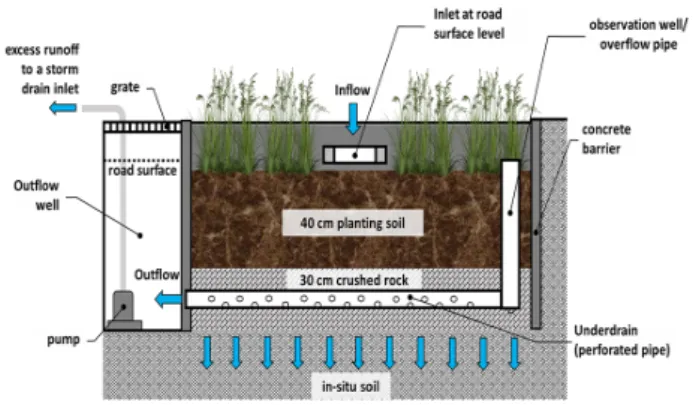
During rainfall, the planter boxes receive stormwater runoff from the asphalt road directly through a concrete gutter and curb inlet on the side of the road. The design characteristics are provided in Table 1. The planter boxes are identically sized and employs 40 cm of planting soil on top of 30 cm of crushed rock (Fig. 1). The plant employed was Kerria Japonica Pleniflora (Japanese Rose) which is a native plant in Korea. Also, upon conducting site investigation, the actual catchment area of PB1 and PB2 were found to be 3 and 11 times larger than the design catchment area, respectively. Both of the facilities are designed to store, treat, and infiltrate 12.4 mm of rainfall to ensure the capture of first flush which contains the bulk of pollutant loads in a rainfall event.
Fig. 1. Longitudinal section of the planter box
Table 1. Physical design characteristics of the planter boxes
Design Parameter PB1 PB2
Surface Area (m2) 4.34 4.34
Design Catchment Area (m2) 106 71 Actual Catchment Area (m2) 1215 221
Total Depth of Media (cm) 70 70
Ponding Depth (m) 10 10
2.2 Sampling and Analysis
Since the start of operation on September 2016, performance monitoring was conducted six times (E1-E6) from September to October of 2016. Of these events, E1, E2, and E3 are done using artificial stormwater runoff due to the scarcity of rainfall during this period.
The artificial runoff was made by mixing highway sediments with groundwater. The sediments were collected through a highway clean-up process, taken to the laboratory, oven-dried for 24 hours, and sieved to remove foreign materials, stones, and other large debris. Then, 5 kg of the sediment was diluted with 100L of water to produce a highly concentrated mixture of 50,000 mg/L. During sampling, this mixture is then made to flow through the road gutter and further diluted with groundwater until it reaches the inlet of the planter box to simulate stormwater runoff. This procedure was conducted such that the load of sediments were initially high and decreases with time.
Flow rates were measured from the start of inflow as well as outflow and every 5 minutes thereafter during the first one hour of runoff, and every 10 minutes after the first hour. Grab samples were also collected in the same manner for turbidity measurements and analytical tests to determine the event mean concentration (EMC) of typical
water quality parameters including total suspended solids (TSS), biochemical oxygen demand (BOD), total organic carbon (TOC), total nitrogen (TN), total phosphorus (TP), and heavy metals (Cu and Zn) The same flow rate measurements and grab sampling scheme was done during the monitoring of actual rainfall events E4, E5, and E6.
Flow measurements were conducted by volumetric method while turbidity was measured in situ using Hach 2100Q portable turbidimeter. All the samples are immediately taken to the laboratory for determining water quality parameters.
The removal efficiencies of pollutants were estimated based on the EMCs in the inflow and outflow for events producing outflow. All statistical analysis of data were done using IBM SPSS Statistics.
3. Results and Discussion
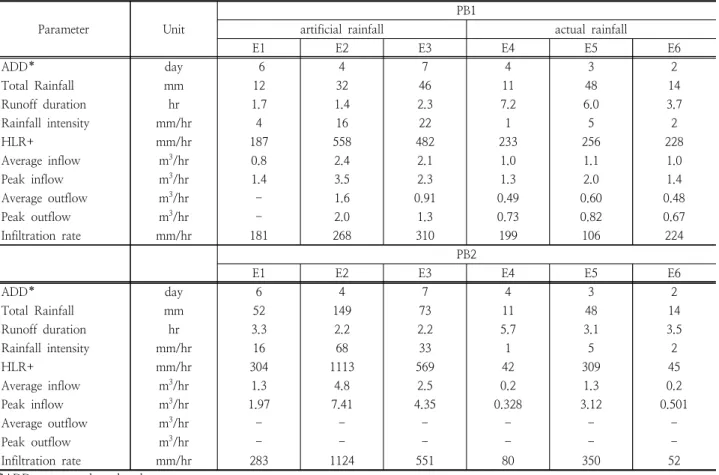
3.1 Hydrologic, Hydraulic, and Pollutant Characteristics The characteristics of the monitored artificial and actual rainfall are summarized in Table 2. The sampled events were captured within the summer/fall season in Korea (June to October) during which 61% of the total annual rainfall and 45% of the rainfall events occurred. The total rainfall
Table 2. Monitored events and hydraulic response in the planter boxes
Parameter Unit
PB1
artificial rainfall actual rainfall
E1 E2 E3 E4 E5 E6
ADD* day 6 4 7 4 3 2
Total Rainfall mm 12 32 46 11 48 14
Runoff duration hr 1.7 1.4 2.3 7.2 6.0 3.7
Rainfall intensity mm/hr 4 16 22 1 5 2
HLR+ mm/hr 187 558 482 233 256 228
Average inflow m3/hr 0.8 2.4 2.1 1.0 1.1 1.0
Peak inflow m3/hr 1.4 3.5 2.3 1.3 2.0 1.4
Average outflow m3/hr - 1.6 0.91 0.49 0.60 0.48
Peak outflow m3/hr - 2.0 1.3 0.73 0.82 0.67
Infiltration rate mm/hr 181 268 310 199 106 224
PB2
E1 E2 E3 E4 E5 E6
ADD* day 6 4 7 4 3 2
Total Rainfall mm 52 149 73 11 48 14
Runoff duration hr 3.3 2.2 2.2 5.7 3.1 3.5
Rainfall intensity mm/hr 16 68 33 1 5 2
HLR+ mm/hr 304 1113 569 42 309 45
Average inflow m3/hr 1.3 4.8 2.5 0.2 1.3 0.2
Peak inflow m3/hr 1.97 7.41 4.35 0.328 3.12 0.501
Average outflow m3/hr - - - - - -
Peak outflow m3/hr - - - - - -
Infiltration rate mm/hr 283 1124 551 80 350 52
*ADD – antecedent dry days
monitored, including the artificial ones, ranged from 11 mm to 149 mm with rainfall intensities ranging from 1.1-67.9 mm/hr. Independent sample t-test analysis among parameters indicates no statistically significant difference in the hydrologic characteristics between PB1 and PB2 (p values = 0.191-0.732) which is due to the close location of the two sites and the same rainfall events monitored.
Outflow was consistently observed in PB1 which means that the storage capacity was exceeded except when the rainfall depth was only 12 mm and the duration is 1.7 hr. However, no outflow was observed in PB2 which indicates treatment of the total runoff during all the monitored events. For small rainfall events, one probable factor is the catchment area for PB2 which is 5 times smaller than that of PB1. This resulted to smaller amounts of runoff that was received by PB2 as compared to PB1 during the actual rainfall events since the two sites are closely located and experience similar rainfall characteristics.
However, during the artificial runoff monitoring, the hydraulic loading and inflow induced in PB2 were higher than that in PB1 and the runoff duration were also longer.
Therefore, it is clear that despite the identical sizing and media configuration of the two planter boxes, PB2 has higher runoff reduction capacity than PB1. The difference in their hydraulic capabilities can be attributed to the possible connection of PB2 to an existing storm drain or a groundwater table. The effect of this design configuration on the performance of the planter box in this study will
be discussed in a succeeding section.
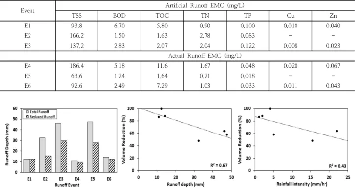
The EMC of selected water quality parameters in the stormwater runoff from artificial and actual rainfall monitoring are presented in Table 3. It can be seen that the artificial runoff characteristics are varying in terms of the pollutant concentrations among the events which follows the behavior of actual runoff. Also, the values between the artificial and actual runoff does not show notable differences which renders the characteristics of the artificial runoff acceptable. The mean±standard deviation of TSS, BOD, TOC, TN, TP, Cu, and Zn in all the events are 123.3±47.7, 3.32±2.17, 5.01±4.02, 1.44±0.91, 0.067±0.041, 0.012±0.005, 00.043±0.018, respectively.
3.2 Runoff Reduction
Fig. 2 shows the runoff reduction in PB1 as well as the trend in runoff volume reduction percentage with respect to rainfall depth and rainfall intensity. It can be seen that PB1 was able to reduce 85-100% of the runoff at rainfall depths of less than 15 mm and rainfall intensities of less than 5 mm/hr. Meanwhile, a volume reduction percentage of 50-64% were observed for rainfall depths of less than 50 mm and rainfall intensities of greater than 5 mm/hr.
Volume reduction decreases with increasing rainfall depth with 4.9% decrease with every 5 mm increase in rainfall based on simple linear regression. This is comparable to the volume reduction attained by the infiltration type BMPs in the study of Maniquiz et al. (2012) with 50-80% reduction
Table 3. EMC of water quality parameters in the stormwater runoff
Event Artificial Runoff EMC (mg/L)
TSS BOD TOC TN TP Cu Zn
E1 93.8 6.70 5.80 0.90 0.100 0.010 0.040
E2 166.2 1.50 1.63 2.78 0.083 - -
E3 137.2 2.83 2.07 2.04 0.122 0.008 0.023
Actual Runoff EMC (mg/L)
E4 186.4 5.18 11.6 1.67 0.048 0.020 0.067
E5 63.6 1.24 1.64 0.21 0.018 - -
E6 92.6 2.49 7.29 1.03 0.033 0.011 0.043
Fig. 2. Runoff reduction observed in PB1
within 20 mm rainfall and 8% of decrease in volume reduction with every 5 mm increase in rainfall.
Research has shown that planter boxes are efficient in reducing runoff volume even without infiltration with 15-20% runoff reduction through containment and evapotranspiration (Hunt et al., 2006). In Korea, more than 80% of the total annual rainfall were 10 mm or less (Yu et al., 2016). Therefore the control in runoff volume achieved by the planter box is satisfactory.
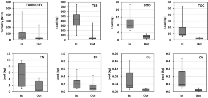
3.3 Pollutant Removal
In each sampling event producing outflow, the total pollutant mass in the inflow and outflow of PB1 (Fig. 3) were calculated to determine the removal of solids, organics, nutrients and heavy metals. Over the monitoring period, the system was able to consistently remove TSS loads by more than 90% while BOD and TOC removal were in the rage of 49-93% and 54-95%, respectively. In the case of nutrients, TN was more effectively removed with 40-94%
efficiency as compared to TP with 26-78% efficiency. Heavy metals Cu and Zn were also removed sufficiently at ranges 62-90% and 84-89% respectively. This pollutant reduction values are highly comparable to the conservative average pollutant reduction percentages presented in the low impact development practices design and implementation guidelines cities in the US.
Planter boxes are considered a moderate stormwater treatment practice with the primary pollutant removal mechanism being filtration and settling (SEMCOG, 2008).
Previous research shows that most of the sediment removal occurs in the top layer while metals removal commonly occurs within the first 45 cm (18 inches) of the soil media (Hsieh and Davis, 2005). On the other hand, nutrient removal is less consistent with phosphorus release observed in some occasions and nutrient removal varying from 1 to 80% (Davis, 2007; Hunt et al., 2006; Hsieh and Davis, 2005).
Statistical analysis between pollutant removals showed strong positive and significant correlation between TSS and
Fig. 3. Pollutant mass removal during the events monitored in PB1
Fig. 4. Trend of pollutants mass removal with rainfall depth and volume reduction
BOD (r=0.93, p=0.022), TOC (r=0.92, p=0.029), TN (r=0.90, p=0.037), and TP (r=0.97, p=0.031) signifying that the organics and nutrients that entered the system are primarily particulate-bound and that physical processes such as sedimentation and filtration dominate the pollutant removal mechanisms.
Meanwhile, Fig. 4 shows that all the pollutants were found to have significant negative correlations to rainfall depth with coefficient of determination (R2) of 0.77 for TSS, 0.63 for BOD, 0.87 for TOC, 0.91 for TN, and 0.83 for TP.
On the other hand, they were found to have positive correlations to volume reduction with R2 values of 0.95 for TSS, 0.98 for BOD, 0.91 for TOC, and 0.86 for TN.
TP showed a relatively lower correlation with volume reduction (R2=0.51). This shows that both hydrologic and hydraulic aspects affect the removal of pollutants in the system. The total rainfall depth is a result of a combination of parameters such as rainfall intensity and duration that will ultimately affect the hydraulic loading of stormwater in the system.
3.4 Design Considerations
Table 4 summarizes several design characteristics of the planter boxes in this study as well as the provisions from different parts of the United States (Geosyntech, 2014;
LADPW, 2014; SEMCOG, 2008; Tetra Tech, 2011). In
comparison, the planter box in this study which was designed based on Korean LID manuals is well within the design guidelines in some states in the USA.
However, different volume reduction capabilities were observed between PB1 and PB2 as discussed in the previous section. Due to the close proximity of the two facilities, the in-situ soil properties and conditions at a certain depth from the bottom of the planters can be assumed similar.
Therefore, the existence of a water table just below the facility is highly unlikely, although not impossible. In the case of a nearby water table, the facility should be redesigned to limit the infiltration based on the guidelines of US manuals regarding minimum separation distances or setbacks.
According to the Construction Stormwater General Permit (CGP) requirements of the National Pollutant Discharge Elimination System/State Disposal System (NPDES/SPS) in the US, there should be minimum vertical and horizontal separation distances or setbacks from the stormwater infiltration facilities to concerned features such as seasonally saturated soils or water table, water supply wells, buildings or other structural foundation, etc. (MSSC, 2005). These setbacks are either recommended or required to prevent negative effects on the facility’s pollutant removal, contamination of water supply and surface waters, and impairment in the stability of any surrounding structural foundations. In most cases, infiltration pathways might need
Table 4. Comparison of design parameters and guidelines
Design Criteria This study California Michigan Florida
Surface area to catchment ratio (%) 0.4/2.0 0.5-3.0 x x
Contributing area (m2) 1215/221 < 4047 (0.35 acre) < 1394 (15000 ft2) < 1011.7 (2.5 acre) Media Configuration
Surface Layer
soil mulch
soil/compost mix mulch
Filter Layer soil soil
Drainage Layer crushed rock stone/gravel gravel gravel
Depth of media (mm) Surface Layer
400 50-100 (2-4 in)
305-914 (12-36 in) 50-75 (2-3 in)
Filter Layer ≥ 305 (12 in) ≥ 610 (2 ft)
Drainage Layer 300 ≥ 305 (1 ft) ≥ 158 (6 in) ≥ 305 (12 in)
Ponding depth (mm) 100 ≤ 457 (18 in) 356 (1 ft 2 in) 158-305 (0.5-1 ft)
Sub-soil infiltration rate x x x x
Drawdown time 1.2-1.7 hr ≤ 48-96 hr < 3-4 hr 48 hrs
Setback from establishments within 10 m x > (3) 10 ft x
Appurtenances
Underdrain yes R O R
Overflow Pipe yes R O R
Geotextile Lining no O R R
Min. distance to water table (m) x > 3 (10 ft) > 0.6-1.22 (2-4 ft) > 0.6 (2 ft) R – required; O-optional; x-not specified
(Values inside parentheses as shown in the reference)
to be restricted because of the close proximity of roads, foundations, and other structures which can be damaged due to the possibility of lateral seepage and rise in groundwater table (Wu and Selvadurai, 2015). These limitations are currently not available in design manuals in Korea and should therefore be included after considering local supplementary research and monitoring data.
On the other hand, assuming that there is a connection between PB2 and an existing storm drain poses a different scenario in terms of performance and monitoring. This means that the storm drain accommodated all the stormwater in excess of the storage and infiltration capacity of the system during high flows. In this case, determining the hydraulic performance and pollutant reduction capability is not possible since the design do not permit access in measuring infiltration rates and sampling of the outflow for water quality analysis. Thus, the current design is not suitable for performance monitoring and can pose a threat to the receiving water body downstream if the target stormwater treatment is not achieved. While sediment and heavy metal reduction is still expected to be high due to the trapping in the soil medium and it’s adsorption capacity, nutrient removal can be compromised at very high infiltration rates since it depends on the runoff retention time within the soil media, where microbial activity can convert nitrogen.
In regards to these possibilities, PB1 can be considered as an infiltration type stormwater planter while PB2 is a combined infiltration and flow-through planter as it allows infiltration of stormwater in the sub-soil while releasing the excess volume in the community storm drains. The infiltration type configuration of PB1 was found to be effective in achieving both high runoff volume and pollutant reduction. On the other hand, the possible combined infiltration and flow-through configuration of PB2 is capable of complete runoff reduction even at high flow rates. However, this design also made it impossible to monitor the effect of the high infiltration rates in its pollutant reduction capacity.
Thus, to ensure that hydraulic and water quality goals in PB2 are met, the underground conditions of the facility should be re-evaluated to be able to perform the appropriate necessary retrofits. In the existence of a nearby groundwater table, infiltration should either be prevented or limited by employing geotextile liners that conform to guideline specifications. In Table 4, it is shown that geotextile lining are commonly employed in planter boxes but was not used in the planter boxes in this study. Based on US design manuals for LIDs (MSSC, 2005; SEMCOG, 2008), infiltration
facilities are allowed only in areas with at least 0.5 in/hr or 12.7 mm/hr permeability. This includes soil groups A to C (NRCS, 2007) or those with infiltration rates of 0.14-5.67 in/hr (3.6-144 mm/hr). The site in this study has a permeability of 1.82 in/hr or 46.4 mm/hr which falls under the Group B soil category. Thus, it is recommended that geotextile liners be installed in infiltration systems to be constructed in areas with soil type A and B (high to moderate infiltration rates). Impermeable hydraulic barriers such as concrete can also be added to the sides and bottom of the facility if infiltration is to be avoided. On the other hand, if a storm drain is connected to PB2, the design of the facility should be changed in a way that would allow monitoring of the runoff volume and pollutant reduction capacity of the system.
This suggested retrofit can improve the pollutant removal by providing longer drawdown and thus, retention times in the facility, as well as lessen the possibility of damage to nearby structures. In addition, it can also provide a chance for better performance monitoring of PB2 since the outflow can be sampled for physico-chemical analysis.
In addition, PB2 was deemed to be oversized with a surface area to catchment area ratio of 2.0 although it is within the recommended ratio that is up to 3.0 as shown in Table 4. Therefore, a ratio of less than 2.0 is recommended for planter boxes such as in this study. It should however be noted that sizing of these systems are also subjected to constraints related to site-specific characteristics such as available surface area and limitations in depth.
4. Conclusions
Based on the analysis of the data gathered from the initial monitoring of the newly constructed stormwater planter boxes in this study, it was found that the infiltration type configuration of one of the planter boxes, PB1, can provide effective reduction of runoff volumes as well as sediments, organics, nutrients, and heavy metals under the hydrologic and site-specific conditions stated. Total runoff retention can also be expected for rainfall events less than 15 mm which constitutes the majority of the rainfall events in Korea.
On the other hand, the uncertainty regarding the hydraulic response of the other planter box, PB2, led to the conclusion that retrofitting or changes in design is needed.
Re-evaluation of underground soil conditions must be done in order to decide what type of retrofits must be done to ensure that the hydraulic and water quality goals can be achieved. The possible existence of a water table near the bottom of the facility would require limiting or totally
preventing infiltration through employing geotextile in accordance to guidelines and specifications, or providing an impermeable concrete barrier on the sides and bottom of the facility. Moreover, if a connection between the underdrain and storm drain is found, it could be disconnected if the re-evaluation renders it not useful or detrimental to the goals of the facility. Another solution is to provide system elements that would allow proper monitoring of PB2.
This results were based on the initially gathered data since the planter boxes were still new. Thus, performance monitoring should be continued to gather more information and provide more accurate conclusions and definitive design evaluation.
Acknowledgement
This research was partially supported by a grant (2016000200002) from Public Welfare Technology Development Program funded by the Korean Misitry of Environment.
References
County of Los Angeles Department of Public works (LADPW) (2014). Low Impact Development Standards Manual, County of Los Angeles Department of Public Works, California.
Davis, AP (2007). Field Performance of Bioretention: Water Quality, Environmental Engineering Science, 24(8), pp.
1048-1064. [DOI: 10.1089/ees.2006.0190]
D’Ambrosio, J, Lawrence, T, and Brown, LC (2014). A Basic Primer on Nonpoint Source Pollution and Impervious Surface, Fact Sheet AEX-444-04, Ohio State University Extension, Ohio.
Gallo, C, Moore, A, and Wywrot, J (2012). Comparing the adaptability of infiltration based BMPs to various U.S.
regions, Landscape and Urban Planning, 106(4), pp.
326-335. [DOI: 10.1016/j.landurbplan.2012.04.004]
Geosyntec Consultants (Geosyntec) (2014). Low Impact Development Practices Design and Implementation Guidance Manual Horizon West Town Center, Orange County Government, Florida.
Hsieh, C and Davis, AP (2005). Evaluation and Optimization of Bioretention Media for Treatment of Urban Storm Water Runoff, J. of Environmental Engineering, 131(11), pp.
1521-1531. [DOI: 10.1061/ASCE0733-93722005131:
111521]
Hunt, WF, Jarrett, AR, Smith, JT and Sharkey, LJ (2006).
Evaluating Bioretention Hydrology and Nutrient Removal
at Three Field Sites in North Carolina, J. of Irrigation and Drainage Engineering, 132(6), pp. 600-608. [DOI:
10.1061/ASCE0733-94372006132:6600]
Kim HK, Jeong, HS, Jeon, JH and Bae, SJ (2016). The Impact of Impervious Surface on Water Quality and Its Threshold in Korea, Water, 8(4), pp. 111-119. [DOI: 10.3390/
w8040111]
Li, ZY and Lam, KM (2015). Statistical evaluation of bioretention system for hydrologic performance, Water Science and Technology, 71(11), pp. 1742-1749.
[DOI:10.2166/wst.2015.131]
Liu, Z, Wang, Y, Li, Z and Peng, J (2013). Impervious surface impact on water quality in the process of rapid urbanization in Shenzhen, China, Environmental Earth Sciences, 68(8), pp. 2365-2373. [DOI: 10.1007/s12665-012-1918-2]
Maniquiz, MC, Choi, JY, Lee, SY and Kim, LH (2012).
Performance comparison between infiltration and non-infiltration type of structural stormwater treatment systems, Water Science and Technology, 66(2), pp.
363-369. [DOI: 10.2166/wst.2012.197]
Minnesota Stormwater Steering Committee (MSSC) (2005).
The Minnesota Stormwater Manual, Ref. No.
wq-strm8-14aw, Minnesota Pollution Control Agency Natural Resources Conservation Service (NRCS) (2007).
National Engineering Handbook Part 630, 210-VI-NEH, Natural Resources Conservation Service US Department of Agriculture.
Southeast Michigan Council of Governments (SEMCOG) (2008). Low Impact Development Manual for Michigan:
A Design Guide for Implementors and Reviewers, Southeast Michigan Council of Governments.
Shuster, WD, Bonta, J, Thurston, H, Warnemuende, E and Smith, DR (2005). Impacts of impervious surface on watershed hydrology: A review, Urban Water Journal, 2(4), pp. 263-275. [DOI:10.1080/15730620500386529]
Tetra Tech, Inc. (2011). San Diego Low Impact Development Design Manual, PITS070111-01, Tetra Tech, Inc. and Construction and Development Standards Section, San Diego Storm Water Division, California.
U.S. Environmental Protection Agency (USEPA) (2017).
https://www.epa.gov/nps/urban-runoff-low-impact- development
Wu, LZ and Selvadurai, APS (2016). Rainfall infiltration- induced groundwater table rise in an unsaturated porous medium, Environmental Earth Sciences, 75(2), pp.
135-145. [DOI:10.1007/s12665-015-4890-9]
Yu, G, Choi, J, Kang, HM and Kim, LH (2016). Evaluation of the Volume and Pollutant Reduction in an Infiltration and Filtration Facility with Varying Rainfall Conditions, J. of Korean Society on Water Environment, 32(1), pp. 30-35.
[DOI: 10.15681/KSWE.2016.32.1.30]