Scheduling North-South Mirror Motion between Two Consecutive Meteorological Images of COMS
Soojeon Lee, Won Chan Jung, and Jaehoon Kim
ABSTRACT
As a multi-mission GEO satellite, Communication, Ocean, and Meteorological Satellite (COMS) is scheduled to be launched in the year 2009. COMS has three different payloads: Ka-band communication payload, Geostationary Ocean Color Imager (GOCI) and Meteorological Imager (MI). Among the three payloads, MI and GOCI have several conflict relationships; one of them is that if MI mirror moves vertically larger than 4 Line Of Sight (LOS) angle while GOCI is imaging, image quality of GOCI becomes degraded. In this paper, MI scheduling algorithm to prevent GOCI’s image quality degradation will be presented.
T
Key Words
TTT: TMirror Motion, Meteorological Imager, COMS, Mission Planning SystemTT
1
T. Introduction
As The major missions of Communication, Ocean, and Meteorological Satellite (COMS) are in the following three categories. [1]
(1) Satellite communications
- Next generation communication payload technology and space qualification
- Broadband satellite multimedia test service (2) Ocean observation (GOCI mission)
- Observation of marine ecology and environment around the Korean peninsula - Assessment of oceanic life and generation of
high quality fishery information
(3) Meteorological observation (MI mission) - Continuous observation of high resolution
multi-channel meteorological images and generation of meteorological elements - Early detection of abnormal meteorological
phenomena such as typhoons, torrential rain, yellow sand, sea fog, and so on.
- Generation of long term sea surface temperature and cloud data
In COMS, there are issues when operating the payloads simultaneously: especially between MI and GOCI. One of them is that if MI mirror moves vertically larger than 4 LOS angle (view angles from Sub Satellite Point) while GOCI is imaging, image quality of GOCI becomes degraded. In this paper, MI scheduling algorithm to prevent GOCI’s image quality degradation will be presented.
2. Overview
2.1. North-South MI Mirror Motion While Imaging MI takes rectangular images around the Korea peninsular. Before taking a meteorological image, MI mirror is placed at the northwest part of the requested image area.
The mirror performs imaging while moving to the easternmost part of the image area horizontally. After completing imaging for one horizontal line, the mirror moves to the westernmost part of the next line and imaging is done for the next line again.
At the time when the imaging is completed, the mirror will be placed at the southeast part of the requested imaging area.
* Electronics and Telecommunications Research Institute 161 Gajeong-dong Yuseong-gu Daejeon, KOREA 305-700 Email: {soojeonlee, wcjung,
HTUjhkim}@etri.re.kr
UTH논문번호 : K3-2-5 , 접수일자 : 2008년 11 월 28일, 최종게재논문통보일자 : 2008 년 12 월 26일
The north-south mirror motion while imaging is too slow to degrade the image quality of GOCI.
2.2. North-South MI Mirror Motion between Two Consecutive Imaging
(1) Automatic Movement
After completing imaging, the mirror automatically moves to the nadir as quickly as possible to protect the MI from the sunlight.
However, if this quick automatic movement is done vertically more than 4 LOS angle while GOCI is imaging, image quality of GOCI becomes degraded.
(2) Manual Movement
Operator can handle the mirror not to move to the nadir after completing imaging. This is required in several cases. One of examples is when the distance between nadir and the northernmost part of the next image is too far. In these cases, after completing imaging the mirror moves to nadir automatically and then move again to the northernmost part of the next image;
it takes time and may degrades the GOCI’s image quality.
To prevent the disadvantage of automatic movement, manual movement can be used. while imaging, operator should send a telecommand to move the mirror to a target latitude (e.g., the northernmost part of the next image).
Even in this quick manual movement, however, if the movement to the target latitude is done vertically more than 4 LOS angle while GOCI is imaging, image quality of GOCI becomes degraded. Thus, in case of manual movement, if the mirror should move more than 4 LOS angle, a method introduced in section 3.2 shall be applied.
3. MI Mission Planning 3.1. MI sequence
A MI sequence consists of a black body calibration (BB-cal) and images. The maximum length of a MI sequence is 1800 seconds.
A MI sequence begins with BB-cal which takes 48 seconds. After BB-cal finishes, 20 seconds should be passed without imaging and then the
first image can be taken. For the simplicity, in this paper, we assume that a MI sequence begins at - 48s and finishes at 1754s.
3.2. Intermediate Step
P
1
P
To prevent MI mirror not to move to the nadir after imaging, a telecommand called intermediate step is used. By using intermediate step, the mirror moves to the target latitude and pauses for 10 seconds. This prevents the quick and more- than-4-LOS-angle movement of the mirror. Let us call the mirror location after imaging location, and the LOS angle the mirror moved after imaging angle. Then, default intermediate step insertion policy [2] is shown in Figure 1.
1) if |Angle| <= 4 Insert no Intermediate step
2) if 4 < |Angle| <= 8
Insert one Intermediate step at “Location + Angle*1/2"
3) if 8 < |Angle| <= 12
Insert one Intermediate step at “Location + Angle*1/3"
Insert one Intermediate step at “Location + Angle*2/3"
4) if 12 < |Angle| <= 16
Insert one Intermediate step at “Location + Angle*1/4"
Insert one Intermediate step at “Location + Angle*2/4"
Insert one Intermediate step at “Location + Angle*3/4"
5) if 16 < |Angle|
Insert one Intermediate step at “Location + Angle*1/5"
Insert one Intermediate step at “Location + Angle*2/5"
Insert one Intermediate step at “Location + Angle*3/5"
Insert one Intermediate step at “Location + Angle*4/5"
Figure 1: Data Spread
However, the above policy is not always used.
For example, even if the angle is larger than 8 LOS, the last image in a MI sequence is followed by just one intermediate step.
4. User Requirement
4.1. Margin
There should be a margin between two consecutive images in a MI sequence. The margin
TP
1
PT
Hereafter, for the simplicity, horizontal movement of MI will not be mentioned; MI movement means vertical one.
Global
<<entity>>
+offset +sequence +frame_end +margin +first_image +offset_finished_by_image +idle_first_1 +idle_1 +idle_2 +idle_3 +idle_4 +idle_INT +idle_image +optimal
Image
<<boundary>>
+margin_to_start +margin_from_start +actual_start_time +duration +requested_start_time +set_actual_start_time() +get_actual_start_time()
Int_steps
<<boundary>>
+num_of_int_steps +start_time_list +set_start_time() +get_start_time_list()
Image_unit
<<boundary>>
+image +int_steps +get_actual_start_time() +get_start_time_list()
varies depending on the operator’s input.
4.2. Optimality
Operator wants to take images as many as possible in a MI sequence. However, in some cases, some of the requested images may not be taken. For example, if 4 intermediate steps are inserted between two consecutive images, there should be interval at least 40 seconds and margin.
It means that some images should be delayed due to the unexpected intermediate steps and excluded from the MI sequence due to exceeding the maximum length of the MI sequence (1800s).
Thus, if optimality should be pursued rather than satisfying user requested imaging start time, it is necessary to compress the imaging schedule as much as possible in a MI sequence.
5. Algorithm Description
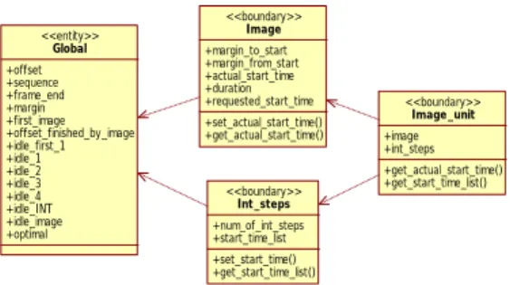
We describe the scheduling algorithm using class diagram in 5.1 and pseudo code in 5.2.
5.1. Class Diagram
Following 4 classes are introduced in this section. Figure 2 shows the class diagram of the classes.
(1) Global
This defines the global variables used in the scheduling algorithm.
(2) Image
This defines an image.
(3) Int_Steps
This defines intermediate step(s) followed by an image.
(4) Image_unit
An image and the intermediate steps following the image are considered an image unit.
Figure 2: Class Diagram
5.2. Pseudo Code
Above classes are described using pseudo code with python syntax [3].
5.1. Global
class Global:
offset=0 # offset time sequence=[-48, 1752]
frame_end=0 # image frame end time margin=0
first_image=True # flag indicating whether current image is the first one in a MI sequence
offset_finished_by_image=False # flag indicating whether current offset is finished by image or INT
idle_first_1=14 # idle time from the first proportional command of a MI sequence (#1~) idle_1=6 # idle time from proportional commands (#1~)
idle_2=6 # idle time from proportional commands (#2~)
idle_3=10 # idle time from proportional commands (#3~)
idle_4=10 # idle time from proportional commands (#4~)
idle_INT=10 # idle time from proportional commands (INT~)
idle_image=10 # idle time from the end of an image
optimal=False # whether to pursue optimality or not
5.2. Image
class Image:
def __init__(self, requested_start_time, duration):
self.requested_start_time=requested_start_ti me # requested imaging start time
if Global.first_image==True:
Global.first_image=False
self.margin_to_start=Global.idle_first_1+Glo bal.idle_2
elif
Global.offset_finished_by_image==True:
self.margin_to_start=Global.idle_1 elif
Global.offset_finished_by_image==False:
self.margin_to_start=Global.idle_1+Global.id le_2
self.margin_from_start=Global.idle_3 + Global.idle_4
self.actual_start_time=None self.duration=duration
def set_actual_start_time(self, optimal):
if optimal==False:
if self.requested_start_time - self.margin_to_start >= Global.offset:
self.actual_start_time=self.requested_start_
time else:
self.actual_start_time=Global.offset+self.margin_to_start elif optimal==True:
self.actual_start_time=self.margin_to_start + Global.offset
Global.offset=self.actual_start_time + self.margin_from_start
Global.frame_end=self.actual_start_time + self.duration
if Global.offset >= Global.sequence[1]
or Global.frame_end >= Global.sequence[1]:
print 'ERROR: sequence over the limit', Global.offset, Global.frame_end, Global.sequence[1]
return False
if Global.frame_end <= Global.offset:
print 'ERROR: too small image' return False
return True
def get_actual_start_time(self):
return self.actual_start_time
5.3. Int_steps
class Int_steps:
def __init__(self, num_of_int_steps):
self.num_of_int_steps=num_of_int_steps self.start_time_list=[]
def set_start_time(self):
if self.num_of_int_steps == 0 or self.num_of_int_steps == 1: # finished by not INT but image
Global.offset_finished_by_image=True else:# finished by not image but INT
Global.offset_finished_by_image=False
if self.num_of_int_steps == 0:
Global.offset=Global.frame_end + Global.idle_image + Global.margin
else:
for i in range(self.num_of_int_steps):
if Global.offset >= Global.sequence[1]:
print 'ERROR: int_step sequence over the limit', Global.offset, Global.sequence[1]
return False
self.start_time_list.append(Global.offset) if i==0:
Global.offset=Global.frame_end + Global.idle_image + Global.margin
else:
Global.offset=Global.offset + Global.idle_INT + Global.margin
def get_start_time_list(self):
return self.start_time_list
5.4. Image_unit
class Image_unit: # image + intermediate steps
def __init__(self, requested_start_time, duration, num_of_int_steps, optimal):
self.image=Image(requested_start_time, duration)
self.int_steps=Int_steps(num_of_int_steps) self.optimal=optimal
def do(self):
if
self.image.set_actual_start_time(self.optima l)==False: # optimal==True, not optimal==False return False
if self.int_steps.set_start_time()==False:
return False
def get_actual_start_time(self):
return
self.image.get_actual_start_time()
def get_start_time_list(self):
return
self.int_steps.get_start_time_list()
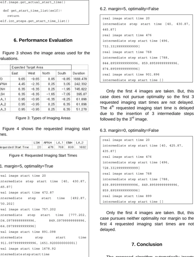
6. Performance Evaluation
Figure 3 shows the image areas used for the evaluations.
Figure 3: Types of Imaging Areas
Figure 4 shows the requested imaging start times.
Figure 4: Requested Imaging Start Times
6.1. margin=5, optimality=True
real image start time 20
intermediate step start time [40, 430.87, 445.87]
real image start time 472.87
intermediate step start time [492.87, 730.202]
real image start time 757.202
intermediate step start time [777.202, 834.09799999999996, 849.09799999999996, 864.09799999999996]
real image start time 891.098
intermediate step start time [911.09799999999996, 1651.9200000000001]
real image start time 1678.92 intermediate step start time [1698.9200000000001]
5 images are all taken. But, to pursue optimality, all the requested imaging start times are shifted ahead except the first one.
6.2. margin=5, optimality=False
real image start time 20
intermediate step start time [40, 430.87, 445.87]
real image start time 476
intermediate step start time [496, 733.33199999999999]
real image start time 768
intermediate step start time [788, 844.89599999999996, 859.89599999999996, 874.89599999999996]
real image start time 901.896 intermediate step start time []
Only the first 4 images are taken. But, this case does not pursue optimality so the first 3 requested imaging start times are not delayed.
The 4
Pth
P
requested imaging start time is delayed due to the insertion of 3 intermediate steps followed by the 3
Prd
P
image.
6.3. margin=0, optimality=False
real image start time 20
intermediate step start time [40, 425.87, 435.87]
real image start time 476
intermediate step start time [496, 728.33199999999999]
real image start time 768
intermediate step start time [788, 839.89599999999996, 849.89599999999996, 859.89599999999996]
real image start time 899 intermediate step start time []
Only the first 4 images are taken. But, this case pursues neither optimality nor margin so the first 4 requested imaging start times are not delayed.
7. Conclusion
The proposed algorithm automatically inserts proper intermediate steps after an image.
Moreover, to include maximum number of images
in a MI sequence, it supports optimality function to
compress the imaging schedule as much as possible.
Reference
[1] Specifications for Mission Planning Subsystem in COMS SGCS, rev.D, ETRI TD, July 2007 [2] F.Souquet-Basiege, COMS Mission Planning
Specification (SYS-48), COMS.SPT.00005.
DP.T.ASTR (issue 5. version 2) [3] http://www.python.org
.
U
저 자 이 수 전(Soojeon Lee)
Received the BS degree in Computer Science from Korea University, Korea in 2003, and the MS degree in Computer Engineering from Information and Communica- tions University (ICU), Korea in 2005.
He has worked as Research Staff in Electronics and Telecommunications Research Institute (ETRI) from 2005.
His research interests include operation and mission planning of satellite ground control system .
정 원 찬(Won Chan JUNG)
Received BS degree in Computer Science at Henderson State University in 1986 and Ph.D. degree in Computer Science at Louisiana State University in 1992.
He joined ETRI in 1992 and is a principal member of engineering staff.
He has been developing the satellite ground control system for KOMPSAT-1 and KOMPSAT-2, and now he is currently developing satellite ground control system for COMS satellite .
김 재 훈(Jae-Hoon Kim) Received the PhD degree in computer engineering from Chungbuk National University, Cheongju, Korea in 2001.
He joined ETRI in 1983, where he was involved in developpping the Intelli-gent Network and KOREASAT Projects.
From 1992 to 1994, he was an OJT Engineer in Martra-Marconi Space in the U.K. for the KOREASAT Project. From 1995 to 1999, he participated in the KOMPSAT-1 Ground Mission Control Project as a Principle Member of Engineering Staff in System Engineering.
From 2000 to 2005, he participated in the KOMPSAT-2 Ground Mission Control Project as Team Leader. He is now working for the COMS- 1, KOMPSAT-3 and KOMPSAT-5 Ground Mission Control Projects as Team Leader.
His research interests are security in satellite communications, fault diagnosis of satellites using AI technologies, and system modeling using objected-oriented technolo- gies.