http://dx.doi.org/10.7839/ksfc.2019.16.3.023
Position Sensorless Control of PMSM Drive for Electro-Hydraulic Brake Systems
Seungjin Yoo
1, Yeongrack Son
2, Jung-Ik Ha
2, Cheol-Gyu Park
3and Seung-Han You
4*Received: 07 May 2019, Revised: 31 Jul. 2019, Accepted: 11 Aug. 2019
Key Words:Degraded Control, Electro-Hydraulic Brake, Fault Tolerant Control, Permanent Magnet Synchronous Motor, Position Sensor Fault
Abstract: This study proposed a fault tolerant control algorithm for electro-hydraulic brake systems where permanent magnet synchronous motor (PMSM) drive is adopted to boost the braking pressure. To cope with motor position sensor faults in the PMSM drive, a braking pressure controller based on an open-loop speed control method for the PMSM was proposed. The magnitude of the current vector was determined from the target braking pressure, and motor rotational speed was derived from the pressure control error to build up the braking pressure. The position offset of the pump piston resulting from a leak in the hydraulic system is also compensated for using the open-loop speed control by moving the piston backward until it is blocked at the end of stroke position. The performance and stability of the proposed controller were experimentally verified.
According to the results, the control algorithm can be utilized as an effective means of degraded control for electro-hydraulic brake systems in the case that a motor position sensor fault occurs.
* Corresponding author: [email protected]
1 Korea Institute of Machinery and Materials, Daejeon 34103, Korea
2 Department of Electrical & Computer Engineering, Seoul National University, Seoul 08826, Korea
3 Korea Institute of Industrial Technology, Daegu 42994, Korea
4 School of Mechanical Engineering, Korea University of Technology and Education, Cheonan 31253, Korea
Copyright Ⓒ 2019, KSFC
This is an Open-Access article distributed under the terms of the Creative Commons Attribution Non-Commercial License(http://
creativecommons.org/licenses/by-nc/3.0) which permits unrestricted non-commercial use, distribution, and reproduction in any medium, provided the original work is properly cited.
Nomenclature
J : rotational inertia of motor
: angle of motor (mechanical angle)m
: load torquel
: motor torquec
I: magnitude of current vector
*
m: angle of current vector
Np: number of pole
f: back electromotive force coefficient
N p2
e m
: angle of motor (electrical angle)
: angular velocity of motor (electrical angle)e
L: phase inductance R: phase resistance
kp: proportional gain of current controller ki: integral gain of current controller
: closed-loop bandwidth of current control systemc dˆ
i : dˆ axis component of current vector
qˆ
i : ˆq axis component of current vector
ˆ ref
id : dˆ axis component of reference current vector
ˆ ref
iq : ˆq axis component of reference current vector
dˆ
v : dˆ axis component of voltage vector
qˆ
v : ˆq axis component of voltage vector P: braking pressure
P*: Target braking pressure V: volume of brake fluid
Ap: piston area GR: gear ratio
kpr: proportional gain of pressure controller
1. Introduction
Currently, automobile manufacturers are launching series of electric vehicles (EV) and hybrid electric vehicle (HEV) in the global market. It is expected that an increasing number of environmentally friendly vehicles will replace conventional vehicles, owing to support from various encouraging policies such as government subsidies or tax preferences granted to EV and HEV purchasers1).
On the other hand, state-of-the-art autonomous vehicle technologies are leading the vehicle electronics industry.
For example, adaptive cruise control, lane keeping assistance system, and lane departure warning system are now popular in the high-end or middle-end classes of passenger vehicles as safety & convenience features to the drivers. Furthermore, global IT vendors as well as traditional vehicle manufacturers are racing toward the development of unmanned vehicle technology2).
Those technology trends represented by environmentally friendly vehicles and autonomous vehicle call for new brake systems that possess exclusive features that a conventional vacuum brake booster does not provide3-5).
First, the brake system for an EV or HEV should be able to provide boosted braking pressure without the aid of a conventional vacuum pump or the intake manifold pressure of the engine since the vehicles can be run without engine power.
Second, the regenerative braking capability improves the fuel economy of EVs and HEVs by imposing a braking force proportional to the electric power generation. Therefore, the brake system should be able to generate a braking pressure exempt of the regenerated braking torque, to meet the driver's exact braking intention.
Similarly, the function of autonomous driving demands for an active brake system that can generate
an appropriate braking pressure depending on the driving circumstances, even if the driver does not press the brake pedal.
To meet the above requirements, the electro-hydraulic brake system in this study supplies a boosted braking pressure using an electric motor. Instead of a conventional vacuum booster, the electric motor drives the hydraulic piston pump according to the driver's braking intention, which is measured by a brake pedal stroke sensor. The electro-hydraulic brake system can generate the required braking pressure needed by the EVs and the autonomous vehicles with high accuracy and fast dynamic response, such that high-performance autonomous emergency braking functionality can also be realized.
In spite of these advantages, the electro-hydraulic brake system is exposed to a higher probability of critical system faults, owing to its increased number of electronic components and system complexity compared to a conventional brake system. This leads to a number of strict safety integrity level requirements in its design.
Although the electro-hydraulic brake system proposed in this paper can deliver an un-boosted braking pressure from the driver's pedal press by reconfiguring the hydraulic circuit when the electric booster fails, the dangers of the car crash still remain owing to the increased braking distance, especially in emergency braking situations.
Therefore, it is mandatory to achieve functional safety by implementing a fault tolerant control in the electro-hydraulic brake system, which can extend the availability of the electric boosting function even if its electronic components are abnormal. Most of all, the fault tolerant control can be used to cope with malfunction of the position sensor and current sensor, and the dc link voltage sensor is crucial for the three phase PMSM drive, which is adopted as the electric brake booster owing to its high power density and large starting torque.
Motivated by the above requirements, this paper proposes a position sensorless controller that can provide a degraded brake boosting performance of the electro-hydraulic brake system during a motor position sensor fault.
Several kinds of sensorless control techniques for the
PMSM are available, including the high frequency voltage injection technique6-8), back electromotive force estimation technique9,10) and open-loop speed control.
The high frequency voltage injection technique enables motor position estimation at standstill or low speed ranges, using the magnetic saliency or the impedance disparity between the direct and the quadrature axes of the PMSM. The position estimator based on the back electromotive force observer can only be applied from mid- to high-speed ranges, so it is common to use the algorithm in combination with the high-frequency voltage injection technique or the open-loop speed control.
Among the above sensorless algorithms for the PMSM, this paper proposes a braking pressure controller relying only on the open-loop speed control method. The magnitude of the current vector for the open-loop speed control is determined from the target braking pressure, and motor rotational speed is derived from the pressure control error. A method to compensate the position offset of the pump piston is also proposed, where the offset originates from a leak in the hydraulic system. The performance and stability of the proposed controller are experimentally verified and the results prove that the control algorithm can be used as an effective means of degraded control for the electro-hydraulic brake system when a motor position sensor fault occurs.
2. Overview of Electro-Hydraulic Brake System
The electro-hydraulic brake system in this study consists of an input part sensing the driver's braking intention from the pedal stroke sensor and an actuation part controlling the braking pressure according to the input command.
The input part consists of the brake pedal, master cylinder, pedal stroke sensor, and the pedal simulator, which provides the similar pedal feel to that of a conventional brake system. Because this paper focuses on the fault tolerant control of the actuation part, the input part is simplified as a system transforming the driver's intention to the target braking pressure.
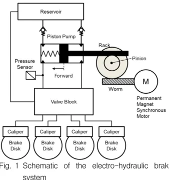
Fig. 1 Schematic of the electro-hydraulic brake system
Fig. 1 shows the actuation part of the electro- hydraulic brake system that consists of a reservoir, an electric motor, a reduction gear, a piston pump, and the valve module.
The reduction gear combines the worm gear and the rack-and-pinion set to deliver the motor torque to the pump piston such that it can generate the boosted braking pressure. This type of gear mechanism is capable of transforming the motor torque to a linear force along the movement direction of the pump piston with a high-speed reduction ratio.
The hydraulic pump of the piston type can supply high-pressure brake oil to each brake caliper without any pressure pulsation. The braking pressure is controlled to precisely follow the target pressure by moving the piston in the forward direction if the pressure measurement is below the target pressure, and moving it in the backward direction if the pressure feedback is above the target pressure. It is also possible to build up the braking pressure by moving the piston in the backward direction depending on the control status of the hydraulic valve module.
The valve module is a hydraulic circuit comprised of a number of solenoid valves, check valves, and orifices.
By controlling the valve module together with the hydraulic pump, the electro-hydraulic brake system can provide the active safety functionality for the vehicle such, as an anti-lock brake system, traction control
system, and electronic stability control.
A surface mounted permanent magnet synchronous motor is adopted to boost the braking pressure featured by the high power density, reduced torque ripple, and the low manufacturing cost.
Fig. 2 depicts the motor driver for the electro-hydraulic brake system. The 12 V battery supplies stable dc power to the inverter through an LC smoothing circuit.
Fig. 2 Control system for the PMSM
A low voltage MOSFET with a minimum switching delay is applied as a power device for the inverter, and the phase currents of the motor are measured by placing the shunt resistors in series with the U and V phases of the motor. A giant magneto resistive position sensor with a built-in fault detection circuit informs the microprocessor of the motor’s position and the fault status of the sensor itself.
Fig. 3 Piston position offset owing to a brake oil leak
Fig. 4 Required motor current according to the braking pressure
Fig. 3 shows experimental test result regarding to the relation between braking pressure and the pump piston position. After the pump supplies the brake oil to the caliper by moving the piston in the forward direction, the braking pressure is released by retracting the piston in the backward direction. In the ideal case where no leak is present in the hydraulic system, the distances traveled in the forward and backward directions would be identical. However, the test results revealed an existing offset in the piston displacement, even though the braking pressure was released to the initial level.
This means that repetition of the braking pressure control would result in a reduced pump stroke in the forward direction, and would eventually lead to a loss of pumping ability if the piston is blocked at the end of the stroke position. Therefore, it is required that the piston be retracted to its initial position, even if the braking pressure is completely released.
Fig. 4 shows the current consumption by the motor, where the Q-axis current is proportional to the motor torque. Because of the seal friction of the pump piston and the friction force in the worm gear, a great discrepancy between the applied torque and released torque is observed.
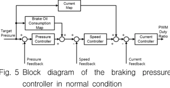
If the control system is in its normal condition, the braking pressure is controlled by the electric motor as depicted by the block diagram in Fig. 5. Provided that the target braking pressure is given by the input part, the electric motor is controlled through the cascade of pressure control, speed control, and current control.
Fig. 5 Block diagram of the braking pressure controller in normal condition
Each controller performs feedback control using the information from the pressure sensor, motor position sensor, and the current sensors, respectively.
Moreover, the feedforward control, utilizing the brake oil consumption characteristics of the caliper as well as the required motor current for the pressure build-up (see Fig. 4), is implemented as look-up tables to improve the dynamic response and the pressure control accuracy.
Since the current map in Fig. 4 changes with brake oil temperature, a nominal map measured at 25℃ is used and the feedforward control error due to the discrepancy was compensated through the feedback controller.
The vector control algorithm for the three phase permanent magnet motor calculates the required voltages to control the motor current, and the duty ratio for the power switch is determined from the space vector pulse width modulation so that the hydraulic pump can accurately supply brake oil according to the target pressure.
3. Design of the Braking pressure Controller
To cope with the position sensor fault in the PMSM drive, this paper presents a braking pressure controller based on the open-loop speed control of the PMSM. A method to compensate the piston position offset induced by the brake fluid leak that can accumulate while applying and releasing the braking pressure repeatedly is also presented.
3.1 State machine
The proposed controller is developed as a state machine, as depicted in Fig. 6, and comprises the ready
mode, pressure control mode, and return mode. If a position sensor fault is detected, the normal braking pressure controller is switched to the fault tolerant controller by entering the ready mode or pressure control mode depending on the target braking pressure at that moment.
In ready mode, the voltage vector of the motor is set to zero by imposing the same duty ratio to all three phases, such that the motor current diminishes to zero and the supply current is not drawn from the battery.
Fig. 6 State machine diagram
If the driver's pedal press is detected, the control mode changes to the pressure control mode and the braking pressure is controlled to follow the target pressure by the open-loop speed control. The mode transition from the pressure control mode to the return mode takes place if the driver takes his foot off the brake pedal and the braking pressure is released.
In the return mode, the open-loop speed controller draws back the pump piston to the end of the stroke position to compensate for the offset caused by the hydraulic system leak. If the pump piston is suspected to be in the end of stroke position, then the mode returns to the ready mode. The decision is made by monitoring the motor current ripple when out of synchronization occurs. The transition from the return mode to the pressure control mode is also possible if the braking intention by the driver is detected while compensating the position offset.
3.2 Braking pressure control using open-loop speed control
The dynamics of the pump piston can be described by Equation (1). The motor torque described by
Equations (2)-(4) shows that the torque is nonlinear with respect to the deviation angle between the target and actual angle of the motor. The torque is proportional to the deviation angle m if it is sufficiently small, but the motor torque is decreased if the deviation angle exceeds 90°, which may lead to system instability.
The motor torque c is also proportional to the motor current I which is included in the torque constant k (see Equation 4) so that the deviation angle can be reduced by increasing the motor current, provided that the load torque l
m,m
remains constant. This means that the system can be regarded as a nonlinear spring-mass- damper system. The control input m* pulls the motor through a nonlinear spring where the stiffness is proportional to the motor current.The basic idea of the proposed algorithm is to control the magnitude of the current vector according to the load torque such that the deviation angle is maintained within a stable range. At the same time, the motor speed is controlled by rotating the current vector according to the target speed.
,
m l m m c
J (1)
sin 2
p
c m
k N
(2)
*
m m m
(3)
3 4 p f
k N I (4)
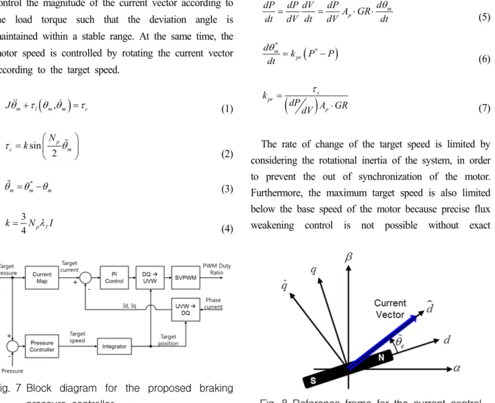
Fig. 7 Block diagram for the proposed braking pressure controller
Fig. 7 shows a block diagram for the proposed braking pressure controller. The current map determines the magnitude of the current vector required to generate the target braking pressure. The dashed line in Fig. 4 shows the designed current map including the marginal current for the system stability.
The target speed of the motor is determined from the pressure controller output. A proportional controller is used to compensate the braking pressure error as in Equations (5) and (6) where the pressure sensitivity
/
dP dV is acquired from the averaged value of the test results given in Fig. 3. The proportional gain for the controller is designed to make the closed loop system behave like the first order system with the time constant as in Equation (7) where it is assumed that s
the rate of change of motor deviation angle in Equation (3) is negligible
m p
d dP dP dV dP
dt dV dt dV A GR dt
(5)
* m *
pr
d k P P
dt
(6)
spr
p
k dPdV A GR
(7)
The rate of change of the target speed is limited by considering the rotational inertia of the system, in order to prevent the out of synchronization of the motor.
Furthermore, the maximum target speed is also limited below the base speed of the motor because precise flux weakening control is not possible without exact
Fig. 8 Reference frame for the current control
information of the motor magnet position. Subsequently, the target position of the motor is derived by integrating the target speed, and it in turn determines the direction of the reference current vector.
By introducing a reference frame rotating with the current vector as depicted in Fig. 8, the reference current vector is interpreted as the ˆd axis current target. The voltage equation expressed in this reference frame is given by Equations (8) and (9), and the current controller is designed as in Equations (10)-(13).
It should be noted that the crossing term dependent on the unknown deviation angle can be compensated using the back electromotive force estimator if tighter current control performance is needed11).
ˆ
ˆ ˆ sin ˆ
d
e q f e
d d
Ldi Ri Li v
dt (8)
ˆ
ˆ
ˆ cos ˆ
q
q e d f e q
Ldi Ri Li v
dt
(9)
ˆ ˆ ˆ ˆ ˆ
ref ref
p i
d d d d d
v k i i k
i i dt (10)
ˆ ˆ ˆ ˆ ˆ
ref ref
q p q q i q q
v k i i k
i i dt (11)p c
k L (12)
i c
k R (13)
The designed controller does not require the position information of the motor magnet, and thus enables braking pressure control during a position sensor fault.
Moreover, the braking pressure controller based on the open-loop speed control of the motor possesses the following advantages and disadvantages when compared to the high frequency voltage injection technique and the back electromotive force estimator.
The open-loop speed control of the motor does not rely on the magnetic saliency or impedance disparity of the motor, such that the method can be applied to both surface mounted permanent magnet (SPM) and interior permanent magnet (IPM) type motors.
The control method based on the high frequency voltage injection technique or the back electromotive
force estimation has limited application depending on the motor type and driving speed. In particular, it is known that the high frequency voltage injection technique cannot be applied to SPM type motors if the impedance is symmetrically distributed. Furthermore, the control method integrating these techniques requires a dedicated transition algorithm. In comparison, the open-loop speed control can be applied to a wider speed range, and it is relatively easy to implement and tune its performance.
However, the open-loop speed control consumes more current compare to the other methods where the maximum torque per ampere strategies are applied using the position information of the motor magnet.
Similar to the previous remark, the maximum braking pressure and its rate of change are limited in cases where open-loop speed control is applied. Moreover, the hunting of the motor owing to a lack of system damping limits the application of the open-loop speed control.
From the above remarks, it can be concluded that the open-loop speed controller is a useful means of position sensorless control when the PMSM drive is applied to a system with low inertia and moderate damping, such as an electro-hydraulic brake system.
3.3 Compensation of the position offset in the return mode
In the case that a brake oil leak is present in the electro-hydraulic brake system, the piston position offset accumulates while applying and releasing the braking pressure repeatedly. If the required displacement of the piston together along with the position offset exceeds the stroke of the piston, it fails to supply the required brake oil to the calipers. Therefore, the piston should be returned to its original position, even after the braking pressure is completely released.
To achieve the above functionality in the return mode, the open-loop speed controller rotates the current vector at a constant magnitude with a predefined rotational speed. The rotation of the current vector continues until the piston is moved to the piston end stroke.
If the piston is confined at the end of the stroke
position, the rotating current vector cannot pull the motor magnet anymore. This induces the out of synchronization of the motor, and results in a ripple current along the q-axis, which otherwise is regulated as zero [A].
ˆ
ˆ ˆ
ˆ ˆ
q q e d f cos e
c q
c q
sLi Ri Li
Li Ri s
(14)
ˆ
ˆ cos
q e d f e
c
i s Li
s Ls R
(15)
Equation (14) describes the current ripple in response to the hunted speed when the out of synchronization takes place. The algorithm in this paper detects this ripple current to complete the position control and change the mode to the ready state. The side effects including noise and vibration induced by the out of synchronization can be minimized by this control algorithm.
4. Experimental Result
For the experimental setup, the prototype electro- hydraulic brake system with 32-bit microprocessor was used. Four brake disks are mounted on the test bench and the brake calipers are connected to the system through the pipe where the pressure sensor is installed to measure the braking pressure. The proposed control algorithm was implemented as embedded software of the microprocessor. The data measurement, controller parameter tuning and the target braking pressure setting was performed using a commercial ECU development tool.
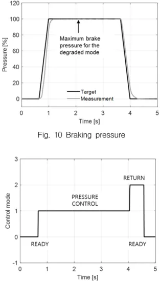
Fig. 9 describes the overall control characteristic of the proposed position sensorless control. When a fault is detected in the motor position sensor, the maximum target pressure in the degraded mode is limited below one half of that in the normal mode. Despite the limited maximum braking pressure, the brake booster remains available under the maximum braking pressure, such that the mode enables the vehicle to limp home or to the nearest service center more safely.
Fig. 9 Braking pressure control characteristic
Figs. 10~15 show the experimental test results of the proposed controller when the brake pedal is pressed and released quickly. This test case is regarded as the worst case in terms of the possible instability incurred by the out of synchronization of the motor.
Fig. 10 Braking pressure
Fig. 11 Control mode
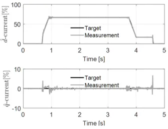
Fig. 12 Motor current
Until 0.7s in the ready mode, the voltage vector remains 0 [V] such that the dˆ and ˆq axis currents converge to 0 [A]. After that time, the control mode changes to the pressure control mode by detecting the target braking pressure. The motor current in the dˆ axis is controlled according to the target pressure and the current vector rotates proportionally to the pressure control error as depicted in Figs. 12 and 13, respectively.
Fig. 13 also shows the speed tracking performance of the motor following the rotational speed of the current vector, which consequently leads to the maximum braking pressure within 0.4s.
After the braking pressure is released at 4s, the control mode changes to the return mode. The current vector of the predefined magnitude rotates the motor to return the piston position as depicted in Fig. 14. In Fig.
12, a ripple current in the ˆq axis is observed at 4.5s
Fig. 13 Motor speed
Fig. 14 Piston displacement
Fig. 15 Load angle (electric angle between the current vector and the magnetic flux)
when the out of synchronization of the motor occurs.
To avoid erroneous detection of the out of synchronization owing to signal noise, it is detected by counting the, guaranteeing that the control system is safe from the out of synchronization. Finally, it is observed that the speed hunting decays within a few milliseconds owing to the system damping, such that it does not give rise to the amplification of the load angle and the system instability.
5. Conclusion
This paper presents the fault tolerant a control algorithm for an electro-hydraulic brake system capable of coping with position sensor faults of a PMSM driven brake booster.
The control algorithm is based on an open-loop
speed controller for the PMSM. The magnitude of the current vector is derived from the motor current required to generate the target braking pressure. The rotational speed of the current vector is determined from the pressure control error.
To return the piston position after the braking pressure is released, a position control algorithm based on the open-loop speed control is presented, where the current ripple induced by the out of synchronization is used to detect the end of stroke position.
Provided that the algorithm is applied to the electro-hydraulic brake system, the advantages and disadvantages of the open-loop speed controller are discussed in comparison to other position sensorless control methods, including the high frequency voltage injection technique and the back electromotive force estimation.
The performance and stability of the proposed controller is experimentally verified using an actual electro-hydraulic brake system prototype. The results show that up to one half of the maximum braking pressure can still be generated within 0.4 second even if the motor position sensor is faulty.
Therefore, it is concluded that the proposed algorithm is applicable to the fault tolerant controller of real electro hydraulic brake system where the load torque can be measured, inertial force is low, and the damping force is moderate.
References
1) Y. X. Yu, E. J. Jeong and K. K. Ahn, “Review of Energy Saving Technology of Hybrid Construction Machine”, Journal of Drive and Control, Vol.15, No.4, pp.91-100, 2018.
2) K. S. Oh and J. H. Seo, “Development of an Automatic Steering-Control Algorithm based on the MPC with a Disturbance Observer for All-Terrain
Cranes”, Journal of Drive and Control, Vol.14, No.2, pp.9-15, 2017.
3) S. Hano and M. Hakiai, “New Challenges for Brake and Modulation Systems in Hybrid Electric Vehicles (HEVs) and Electric Vehicles (EVs)”, SAE Technical Paper 2011-39-7210, 2011.
4) C. von Albrichsfeld and J. Karner, “Brake System for Hybrid and Electric Vehicles”, SAE Technical Paper 2009-01-1217, 2009.
5) M. Park et al., “Development of the ControlLogic of Electronically Controlled Hydraulic Brake System for Hybrid Vehicle”, SAE Technical Paper 2009-01-1215, 2009.
6) J.-I. Ha, “Analysis of Inherent Magnetic Position Sensors in Symmetric AC Machines for Zero or Low Speed Sensorless Drives”, IEEE Transactions on Magnetics, Vol.44, No.12, pp.4689-4696, 2008.
7) J.-H. Jang et al., “Analysis of Permanent-Magnet Machine for Sensorless Control Based on High- Frequency Signal Injection”, IEEE Transactions on Industry Applications, Vol.40, No.6, pp.1595-1604, 2004.
8) S. Kim, J.-I. Ha and S.-K. Sul, “PWM Switching Frequency Signal Injection Sensorless Method in IPMSM”, IEEE Transactions on Industry Applications, Vol.48, No.5, pp.1576-1587, 2012.
9) K.-W. Lee and J.-I. Ha, “Evaluation of Back-EMF Estimators for Sensorless Control of Permanent Magnet Synchronous Motors”, Journal of Power Electronics, Vol.12, No.4, pp.604-614, 2012.
10) J.-K. Seok, J.-K. Lee and D.-C. Lee, “Sensorless Speed Control of Nonsalient Permanent-Magnet Synchronous Motor Using Rotor-Position-Tracking PI Controller”, IEEE Transactions on Industrial Electronics, Vol.53, No.2, pp.399-405, 2006.
11) S.-K. Sul, Control of Electric Machine Drive Systems, John Wiley & Sons, New Jersey, 2011.