https://doi.org/10.5229/JKES.2019.22.4.172
− 172 −
eISSN 2288-9000
Designing of a Novel Core-Shell-Structured Co-free Cathode Material with Enhanced Thermal and Structural Stability
for Lithium Ion Batteries
Ji-Woong Shin, Yun-Chae Nam, and Jong-Tae Son*
Department of Nano Polymer Science & Engineering, Korea National University of Transportation, Chungju, Chungbuk 27469, Korea
(Received October 21, 2019 : Revised November 25, 2019 : Accepted November 27, 2019)
Abstract : The first commercialized cathode material, LiCoO2, suffers from disadvantages such as high cost and toxicity and also possesses safety problems. The nickel-rich LiNi0.9Mn0.1O2 cathode material, used as an alternative to LiCoO2, has highly reversible capacity and high energy density. So, the nickel-rich LiNi0.9Mn0.1O2 cathode material is widely used as an alter- native to LiCoO2 due to its highly reversible capacity and high energy density. However, LiNi0.9Mn0.1O2 has several disadvantages as well, such as poor cycle performance and poor thermal instability. To address these problems, we synthesized a new material, LiNi0.5Mn0.5O2, as a shell on the surface of a core to suppress the surface degradation. The new material showed high structural and thermal stabilities and could also maintain a high capacity. The capacity retention of the core-shell cathode (87.7%) was better than that of the core cathode (76.9%) after 50 cycles. Analysis using differential scanning calorimetry revealed that the heat generation in the core-shell cathode (65.9 Jg-1) was lower than that in the core cathode (559.7 Jg-1).
Keywords : Cobalt-Free, Core-Shell Structure, Cathode Material
1. Introduction
Lithium ion batteries are widely applied in porta- ble electronic devices at present due to their high energy densities, low self-discharge, and tiny mem- ory effect.1,2 The LiCoO2 has been the most widely used cathode material because of its stable electro- chemical cycling and ease of production. However, LiCoO2 cathode material suffers from the disadvan- tages of high cost and toxicity and also possesses safety problems.3-6 Cobalt free LiNi0.9Mn0.1O2 cath- ode material has been proposed as an alternative to LiCoO2 because of its relatively low material cost, structural similarity, and higher discharge capacity.
However, it is difficult to maintain the high capac- ity because its structure is prone to degradation and is accompanied by the release of oxygen, which causes a violent exothermic reaction at a deeply
charged state.7 The layered LiNi0.9Mn0.1O2 cathode material too has some disadvantages. For instance, it has a poor cycle performance because the oxida- tion state of nickel changes from +2 to +4, and Ni4+ being unstable, reacts with the electrolyte and decreases the capacity drastically.8 It is possible to create a functional layer (or shell) on the surface of the inorganic particles (core); materials with such a structure are called the core-shell materials. These materials have attracted a great deal of interest because of their improved physical and chemical properties over their single-component counter- parts.9,10 Ohzuku and Makimura introduced a LiNi0.5Mn0.5O2 cathode material which was differ- ent from LiNiO2. The average oxidation state of nickel in this material was +3, and the formal charges of nickel and manganese were +2 and +4, respectively.11-13 Since tetravalent manganese is elec- trochemically inactive, it provides significant struc- tural stability to the material and results in a
*E-mail: [email protected]
simple topotactic reaction maintaining the hexagonal phase during electrochemical cycling, even at a high voltage cutoff limit of 4.6 V.14-17 Due to its improved structural stability, the onset of the exo- thermic reaction in LiNi0.5Mn0.5O2 is usually at a temperature as high as 280oC, and the heat genera- tion at this temperature is less than that in LiNi0.9Mn0.1O2.18,19 Thus, taking advantages of both high capacity and high thermal stability, we have designed a spherical core-shell material with LiNi0.9Mn0.1O2 as the core and LiNi0.5Mn0.5O2 as the shell. The core delivers a high capacity of around 200 mAhg-1, while the shell provides signifi- cant structural and thermal stability upon electro- chemical cycling. The electrochemical properties and thermal stabilities of the core LiNi0.9Mn0.1O2 and the Li[(Ni0.9Mn0.1O2)1-x(Ni0.5Mn0.5)x]O2 core-shell cathode materials were investigated using electro- chemical testing and differential scanning calorime- try (DSC).
2. Experiment Details
The precursor, Ni0.9Mn0.1(OH)2, and the core-shell material, [(Ni0.9Mn0.1)1-x(Ni0.5Mn0.5)x](OH)2, were syn- thesized via co-precipitation. Aqueous solutions of 1 M NiSO4·6H2O and 1 M MnSO4·H2O were pumped into a 4 L tank reactor with continuous stirring under a N2 atmosphere to generate the pre- cursor. At the same time, NaOH (2 M) and NH4OH solution were separately fed into the reactor. The co-precipitation under vigorous stirring resulted in the formation of spherical particles. In order to construct the core-shell material with a composi- tion of [(Ni0.9Mn0.1)1-x(Ni0.5Mn0.5)x](OH)2, the pre- pared precursor, Ni0.9Mn0.1(OH)2,was continuously mixed with the solution containing the metal com- pounds. The resulting Ni0.9Mn0.1(OH)2, [(Ni0.9Mn0.1)1-x (Ni0.5Mn0.5)x](OH)2 particles were filtered, washed, and then dried in a vacuum oven at 120oC for 24 h. The Li[Ni0.9Mn0.1]O2 and Li[(Ni0.9Mn0.1)1-x (Ni0.5Mn0.5)x]O2 samples were calcined with the pre- cursor and LiOH at 750oC for 10 h in an O2 atmo- sphere. X-ray diffraction (XRD) patterns for the cathodes were obtained using a Siemens D X-ray diffractometer equipped with Cu Kα radiation (λ = 1.54068 Å) in the 2θ range from 10 to 70o. The
morphology of the powder was observed using scanning electron microscopy (SEM). The cathode was fabricated by blending the active material, super P carbon, and binder in 8:1:1 ratio in N- methyl-2-pyrrolidone. The mixed slurry was cast uniformly on a thin Al foil and dried in vacuum for 12 h at 120oC. The electrochemical perfor- mance was tested using a CR2032 coin-type cell, with lithium-metal foil as the anode. A polypropyl- ene microporous film was used as the separator.
LiPF6 (1 M) in a 3:7 (v/v) mixture of ethylene carbonate (EC) and diethyl carbonate (DEC) was used as the electrolyte. The cells were assembled in an argon-filled glove box. The electrochemical per- formances were tested between 2.7 and 4.5 V.
3. Results and Discussion
Fig. 1 shows the SEM images of the core, core- shell, and shell precursors and their corresponding cathode materials. The figure also demonstrates the cross-sectional SEM images and EDS line profile o f t h e c o r e – s h e l l c a t h o d e m a t e r i a l . T h e Ni0.9Mn0.1(OH)2 core precursor was synthesized by co-precipitation and the Ni0.5Mn0.5(OH)2 shell layer was synthesized by changing the composition of the metal solution in the co-precipitation reactor. The diameter of the spherical core and the thickness of the shell layer were ~5 and ~1μm, respectively.
The EDS line profile analysis of the core-shell material shows nearly the intended composition.
The composition of the core cathode material was quite close to the designed composition. The nickel and manganese contents gradually changed from line size 0-1 μm and 5-6 μm. The image of the cross-section confirms that the core-shell cathode material was distinctly divided at the interface of the core and shell, suggesting that the core-shell structure had been successfully synthesized.
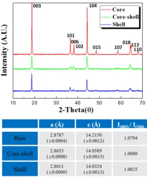
Fig. 2 shows the XRD patterns of the synthe- sized core, core-shell, and shell cathode materials.
The XRD patterns of all the materials can be indexed to the α-NaFeO2 structure (space group R- 3m). The I(003)/I(104) ratios of the core, core-shell, and shell materials were 1.0794, 1.0080, and 1.0025, respectively. The cation mixing, repre- sented as the amount of Ni2+ in lithium layer,
increased with increasing manganese content. Since the total amount of Ni2+ increases with increasing Mn content in Li(Ni2+xNi3+1-2xMn4+x)O2, the Ni2+
content in the lithium layer would also increase.20 Fig. 3 (a) shows the initial charge/discharge capacity curves of the core, core-shell, and shell cells in the cutoff range of 2.7 to 4.5 V at 0.1 C (27.5 mAg-1). The core electrode delivered a high
discharge capacity of 191.4 mAhg-1, while the core- shell and shell electrode exhibited slightly lower capacities of 174.4 and 149.8 mAhg-1. This can be attributed to thelower nickel fraction in the outer layer. To verify the Li-extraction-induced phase transitions during cycling, the dQ/dV profiles of both the cathode materials were obtained by differentiating the charge/discharge curves. The dQ/dV profiles in Fig. 3(b) show a series of phase transitions similar to those observed in Ni-rich cathode materials. The H2 ↔ H3 phase transition above 4.0 V can be attributed to the abrupt lattice shrinkage/expansion of both the core and core–shell electrodes. This H2 ↔ H3 phase transition in the core and core-shell cath- ode materials is likely to be responsible for the structural degradation. The precursor and cathode of the core-shell and shell materials cause capacity loss because the surface of the secondary particles is smooth and denser which makes the lithium ions unable to escape. Thus, in the dQ/dV plot of the first cycle, the core-shell and shell material did not show H2 ↔ H3 phase transition. The relative inten- sities of the H2 ↔ H3 phase transition peaks in the Fig. 1. SEM images of the (a) core precursor, (b) core
cathode material, (c) core-shell precursor, (d) core-shell cathode material, (e) shell precursor, (f) shell cathode material, (g), (h) cross-section of the core-shell cathode material and (i) EDS line profile of the core shell cathode material.
Fig. 2. XRD pattern of the core, core-shell, and shell cathode materials.
dQ/dV profiles of the core, core-shell, and shell cath- ode materials suggest that the detrimental phase tran- sition was substantially suppressed in the core-shell cathode material.
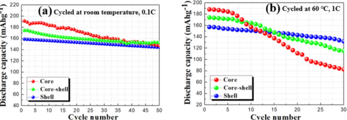
Figs. 4(a) and (b) show the cycling performances of the synthesized core, core-shell, and shell elec- trodes at room temperature and 60oC, at current densities of 27.5 and 275 mAg-1, respectively. The capacity retention of the core and core-shell elec- trodes were 76.9% and 87.7%, respectively, at room temperature after 50 cycles, suggesting that the capacity retention of the core-shell electrode was much higher than that of the core electrode. The capacity retention of the shell electrode was 90.7%.
Even at high temperature, the capacity retention of the core-shell cathode material was 66.3% after 30 cycles, which outperformed that of the core cathode material (43.9% capacity retention). The poor cycling performance of Ni-rich cathode material
could originate from the formation of impurity Lix- Ni1-xO phase from Li1-δ[Ni1-xMx]O2 due to the pres- ence of highly reactive and unstable Ni4+, which can increase the interfacial impedance and thus decrease the cycle life of the cell. We believe that the decreased Ni concentration and the increased Mn concentration in the outer shell layer play an important role in stabilizing the near-surface region of the core-shell cathode material and reduce its reactivity with electrolyte.21,22
Fig. 5 shows the DSC profiles of the core and core-shell materials charged to 4.5 V in the pres- ence of 1 M LiPF6/EC:DEC electrolyte. The onset temperature for the exothermic reaction peak in the DSC thermogram of the core material is 227.9oC;
the corresponding temperature for the core-shell material is 244.7oC. This indicates the reduced heat generation in the core-shell material as compared with that of the core material.
Fig. 3. (a) Initial charge/discharge curves and (b), (c) differential capacity (dQ/dV) curves of the core, core-shell, and shell cathode materials.
Fig. 4. Cycling performances of the core, core-shell, and shell cathode materials at (a) 0.1 C at room temperature and (b) 1 C at 60oC.
4. Conclusions
The electrochemical and thermal properties of the L iN i0 . 9Mn0 . 1O2 c o r e a n d L i [ ( N i0 . 9Mn0 . 1O2)1 -
x(Ni0.5Mn0.5)x]O2 core-shell particles synthesized by c o - p r e c i p i t a t i o n w e r e c h a r a c t e r i z e d . T h e LiNi0.9Mn0.1O2 core electrode delivered a high capacity, while the LiNi0.5Mn0.5O2 shell provided high thermal and structural stability. In lithium ion cells, the core-shell electrode exhibited an excellent cyclability with a capacity retention of 87.7% after 50 cycles, while the core electrode exhibited a capacity retention of only 76.9% for the same num- ber of cycles in the same cells. In the 50 cycle dQ / dV plot, the phase transition peaks of the core- shell and shell material was significantly reduced compared to the core material. As a result, the amount of electrochemically inactive Mn4+ increases, confirming that the crystal structure has stabilized.
Also, the cycle performance at room temperature and high temperature were excellent. The thermal stability of the fully charged core-shell electrode was found to be considerably better than the core electrode. We propose that the core-shell-structured cobalt-free cathode material having high capacity and high thermal and structural stability can be suitably used in rechargeable lithium ion batteries.
Acknowledgment
This study was supported by the financial
resources granted by the Ministry of Trade Program on Industry & Energy, Republic of Korea (Grant No. G02N03620000901) and National Research Foundation of Korea (NRF) grant funded by the Korea government (MIST) (No.2019R1F1A1057220)
References
1. T. Sasaki, Y. Ukyo, and P. Novaak, J. Nat. Mater., 12, 569 (2013).
2. Y. P. Zhang, E. Q. Liang, J. X. Wang, B. J. Yu, C. Y.
Wang, and M. W. Li, Int. J. Electrochem. Sci., 12, 9051 (2017).
3. M. S. Islam, R. A. Davies, and J. D. Gale, Chem. Mater., 15, 4280 (2003).
4. Jeffery W. and Fergus, J. Power Source, 195, 939 (2010).
5. D. Li, C. Yuan, J. Dong, Z. Peng, and Y. Zhou, J. Solid State Chem., 12, 323 (2008).
6. D. Gao, Y. Li, X. Lai, J. Bi and D. Lin, J. Alloys Comp., 509, 697 (2011).
7. H. Arai, S. Okada, Y. Sakurai, and Yamaki, J. Solid State Ionics, 109, 295 (1998).
8. F. L. Liu, S. Zhang, C. Deng, Q. Wu, M. Zhang, F. L.
Meng, H. Gao, and Y. H. Sun, J. Electrochem. Soc., 159, 1591 (2012).
9. I.L. Radtchenko, G.B. Sukhorukov, N. Gaponik, A. Kor- nowski, A.L. Rogach, and H. Mohwald, Adv. Mater., 13, 1684 (2001).
10. Y. K. Sun, S. T. Myung, B. C. Park, and K. Amine, Chem.
Mater., 18, 5159 (2006).
11. T. Ohzuku and Y. Makimura, Chem. Lett., 30, 744 (2001).
12. W. Ahn, S. N. Lim, K. N. Jung, S. H. Yeon, K. B. Kim, H.
S. Song, and K. H. Shin, J. Alloys Comp., 609, 143 (2014).
13. Z. Lu, L.Y. Beaulieu, R.A. Donaberger, C.L. Thomas, and J.R. Dahna, J. Electrochem. Soc., 149, 778 (2002).
14. X.Q. Yang, J. McBreen, S.W. Yoon, and C.P. Grey, Elec- trochem. Commun., 4, 649, (2002).
15. S.T. Myung, S. Komaba, K. Hosoya, N. Hirosaki, U.
Miura, and N. Kumagai, Chem. Mater., 17, 2427 (2005).
16. Z. Lu, L.Y. Beaulieu, R.A. Donaberger, C.L. Thomas, and J.R. Dahn, J. Electrochem. Soc., 149, 778 (2002).
17. Y. K. Sun, S. T. Myung, M. H. Kim, J. Prakash, and K.
Amine, J. Am. Chem. Soc., 127, 13411 (2005).
18. S.H. Kang, J. Kim, M.E. Stoll, D. Abraham, Y.K. Sun, and K. Amine, J. Power Source, 112, 41 (2002).
19. S. Jouanneau, D.D. MacNeil, Z. Lu, S.D. Beattie, G. Mur- phy, and J.R. Dahn, J. Electrochem. Soc., 150, 1299 (2003).
20. Y. K. Sun, D. J. Lee, Y. J. Lee, Z. Chen, and S. T. Myung, ACS Appl. Mater Interfaces, 5, 11434 (2013).
21. Y. K. Sun, D. H. Kim, C. S. Yoon, S. T. Myung, J. Prakash and K. Amine, Adv. Funct. Mater., 20, 485 (2010).
22. Y. K. Sun, B. R. Lee, H. J. Noh, H. Wu, S. T. Myung and K. Amine, J. Mater. Chem., 21, 10108 (2011) Fig. 5. DSC traces of the core, core-shell, and shell
cathode materials charged to 4.5 V.