Original Article
Guideline on Acceptance Test and Commissioning of High-Precision External Radiation Therapy Equipment
Juhye Kim*, Dong Oh Shin
†, Sang Hyoun Choi
‡, Soonki Min
†, Nahye Kwon
§, Unjung Jung*, Dong Wook Kim
ΙΙ*Research Institute of Clinical Medicine, Kyung Hee University Hospital at Gangdong,
†Department of Radiation Oncology, Kyung Hee University Hospital,
‡Division of Medical Radiation Equipment, Korea Institute of Radiological and Medical Sciences, Seoul,
§Department of Nuclear Engineering, Kyung Hee University, Yongin,
ΙΙDepartment of Radiation Oncology, Kyung Hee University Hospital at Gangdong, Seoul, Korea
Received 20 November 2018 Revised 13 December 2018 Accepted 14 December 2018
Corresponding author
Dong Wook Kim ([email protected]) Tel: 82-2-440-7398 Fax: 82-2-440-7393
The complex dose distribution and dose transfer characteristics of intensity-modulated radiotherapy increase the importance of precise beam data measurement and review in the acceptance inspection and preparation stages. In this study, we propose a process map for the introduction and installation of high-precision radiotherapy devices and present items and guidelines for risk management at the acceptance test procedure (ATP) and commissioning stages.
Based on the ATP of the Varian and Elekta linear accelerators, the ATP items were checked step by step and compared with the quality assurance (QA) test items of the AAPM TG-142 described for the medical accelerator QA. Based on the commissioning procedure, dose quality control protocol, and mechanical quality control protocol presented at international conferences, step-by-step check items and commissioning guidelines were derived. The risk management items at each stage were (1) 21 ionization chamber performance test items and 9 electrometer, cable, and connector inspection items related to the dosimetry system; (2) 34 mechanical and dose-checking items during ATP, 22 multileaf collimator (MLC) items, and 36 imaging system items; and (3) 28 items in the measurement preparation stage and 32 items in the measurement stage after commissioning.
Because the items presented in these guidelines are limited in terms of special treatment, items and practitioners can be modified to reflect the clinical needs of the institution. During the system installation, it is recommended that at least two clinically qualified medical physicists (CQMP) perform a double check in compliance with the two-person rule. We expect that this result will be useful as a radiation safety management tool that can prevent radiation accidents at each stage during the introduction of radiotherapy and the system installation process.
Keywords: External radiation therapy equipment, Acceptance test, Commissioning, IMRT, Risk management
Copyright © 2018 Korean Society of Medical Physics
CCThis is an Open-Access article distributed under the terms of the Creative Commons Attribution Non-Commercial License (http://creativecommons.org/licenses/by- nc/4.0) which permits unrestricted non-commercial use, distribution, and reproduction in any medium, provided the original work is properly cited.
Introduction
Intensity modulated radiation therapy (IMRT) is a treat- ment that irradiates high dose to target volume while providing minimum dose to surrounding tissue by making optimal dose distribution with non-uniform fluence com-
pared with 3-dimentional conformal radiation therapy (3D CRT).
1)The introduction of such highly advanced treat- ment techniques has made the examination of the dose measurement also very important, not only increased the necessity of dose-based validation but also the importance of the dose distribution and the dose transfer characteristic
Progress in Medical Physics 29(4), December 2018 https://doi.org/10.14316/pmp.2018.29.4.123 eISSN 2508-4453
unique to the inverse planning technique. Accurate dose delivery in radiation therapy is highly dependent on the accuracy of the measured beam data during acceptance test procedures (ATP) and commissioning. Especially, the beam commissioning in the treatment planning system is very essential for clinical applications of IMRT. Most of the acquired beam data is input to the treatment plan- ning system to determine or model the characteristics of the treatment device and is treated as standard data for clinical use. These standard data not only affect the treat- ment plan of all patients, but also serve as a basis for the quality assurance of the treatment device. Therefore, the linear accelerator ATP and commissioning phases are very important steps because they are the first step in the risk management system of the corresponding treatment equipment. When installation of linear accelerator, the clinically qualified medical physicist (CQMP) must take all the steps from the detailed construction plan to the treatment room design, installation supervision, ATP and beam data measurement to ensure the safety and accuracy of radiation therapy.
2)Furthermore, it is very important to maintain and guarantee the quality control standard value of radiotherapy equipment. The American Association of Physicists in Medicine (AAPM), European Society for Ra- diotherapy & Oncology (ESTRO), and International Atomic Energy Agency (IAEA) have published reports on dose quality control protocols
3,4)and mechanical quality control protocols.
5,6)Reports on beam commissioning related to accelerator beam data measurement or dose verification of advanced treatment techniques have also been pub- lished,
7-10)but there are no official reports for ATP items, yet. Despite the fact that new high precision radiotherapy devices are constantly being introduced in many hospitals in Korea, there are no guidelines for ATP or commissioning stages that are appropriate for domestic situations.
Thus, we propose risk management items for the dosim- etry system itself, ATP and commissioning, and propose risk management guidelines for them.
Materials and Methods
ATP of high precision external radiation therapy equip- ment is part of an agreement to accept the acquisition,
which means that the manufacturer verifies that the per- formance and operation of the device meet the specifica- tions with the user. Step items and tolerances of ATP were derived based on the acceptance procedure of Varian (Var- ian Medical Systems, Inc. 3100 Hansen Way Palo Alto, CA, USA) and Elekta (Elekta Instrument AB Kungstensgatan 18, Stockholm, Sweden) linear accelerators. The extracted ATP items were confirmed by comparing the AAPM report items as the quality assurance items of medical accelera- tors and the IMRT recommendation criteria. Commission- ing is classified based on the following: (1) acquisition of beam data for treatment planning and dose calculation, (2) modeling of beam data and various parameters entered into the treatment planning system, and classification and approval according to the calculation algorithm, and (3) the dose verification process, which compares the calcu- lated dose with actual measurement results to verify that it is within the tolerance. The step-by-step procedures and risk management items for commissioning and dosimetry system preparation were derived based on reports from overseas associations such as the AAPM TG-106 report,
7)the TG-120 report,
10)the AAPM TG-142 report,
6)the AAPM TG-119
8)and ESTRO booklet no. 9 report.
9)The modeling and dose verification process were previously reported for the commissioning of the radiation treatment plan (RTP) system.
11)In this paper, we derive procedures focusing on the acquisition of beam data in high precision external ra- diation therapy equipment.
Dosimetry systems used in the ATP and commission-
ing phases include ionization chambers, electrometers for
one-dimensional dose measurement, radiochromic films,
and two-dimensional array detectors for two-dimensional
dose distribution measurements. In this paper, it derived
risk management items based on the procedures of using
ionization chambers and electrometers, which are most
widely used for profile and point dose measurement dur-
ing beam commissioning. The ATP of high-precision radio-
therapy devices were divided into three sub-steps: 1) me-
chanical and dose aspects, 2) multi-leaf collimator (MLC),
and 3) imaging system. The risk management items for
each procedure in the commissioning stage are subdivided
into a measurement preparation step and an acquiring
beam data.
Results
1. Dosimetry system
1) Ionization chamber
Humphries and Purdy
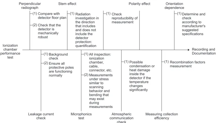
12)suggested that the ionization chamber should be tested first before using it for the first time or before calibrating the ionization chamber. When purchasing an ionization chamber, it is recommended that the enclosed calibration certificate and the results of the performance be recorded, documented, and backed up.
When using an ionization chamber for measurement beam data, especially for ATP and commissioning, it is made of a tissue equivalent material or air equivalent material.
10)The center electrode should be made of a low atomic number material such as aluminum. The shape of ionization cham- ber should be a cylindrical type. The ionization chamber is selected considering the purpose of measurement, beam particle (photon, electron, proton, etc.), energy, and field size. It is necessary to select an ionization chamber with adequate spatial resolution to avoid measurement errors due to the abrupt dose distribution used in the IMRT treat-
ment plan and the number of segments of the treatment field. Especially, it is recommended that the IMRT mea- surement start after the ionization chamber performance test and ionization chamber cross calibration as shown in Fig. 1.
2) Electrometers and cables
The basic requirements of the electrometer are mea- surement accuracy, linearity, stability, sensitivity, high impedance and low leakage dose. The performance of the electrometer should be further considered when using a small volume ionization chamber. It is recommended that cables and connectors used between the electrometer and the ionization chamber should be aware of the precautions for storage and cable connections, as they will affect the measurement results depending on the storage conditions or the setup connection. Electrometer, cable and connec- tor inspection and risk management items were derived in total 21 items (Fig. 2).
Ionization chamber performance
test
Perpendicular radiograph
Stem effect Polarity effect Orientation
dependence Compare with
detector floor plan Check that the detector is mechanically robust
Determine and check according to manufacturer's suggested specifications
Leakage current check
Microphonics test
Atmospheric communication
check
Measuring collection efficiency Background
check Ensure all protective poles are functioning normally
Recording and Documentation (1)
(2)
Radiation investigation in the direction that includes and does not include the detector protection:
quantification
(1) Check
reproducibility of measurement
(1) (1)
(1) (2)
All inspection:
ionization chamber, cable, connector, etc.
Measurements under stress similar to scanning behavior and bending that may exist during measurements (1)
(2)
Possible condensation or heat damage inside the detector if the temperature changes significantly
(1) (1) Recombination factors
measurement
Fig. 1. Ionization chamber performance test.
2. ATP of high-precision radiotherapy equipment
The manufacturer must demonstrate that the radiother- apy unit is operating in accordance with the specifications required by the consignor. Then CQMP shall establish the therapeutic beam characteristics required for clinical use
during ATP and commissioning, shall establish a reference value, and verify that it is operating within the specified tolerances. CQMP play a key role in the team conducting shielding, design of the radiotherapy room, and ATP of ra- diotherapy machine. Furthermore, CQMP should establish and conduct ATPs based on procedures (ATP or customer
Electrometers, cables and adapters check
Check cables, connectors and adapter connection
error factors
(1) Check the cable connector type: BNC, TNC, M type, etc.
(2) Cable check: Coax, Triax
(3) Check cable connector: male, female (4) Check cable storage: twisted, crushed, etc.
(1) Polarity effect check: unipolar, bi olar (2) Input offset current
(3) Check the input voltage offset (4) Continuity check
(5) Gain, autorange variation check (6) Signal saturation check (7) Signal-to-noise ratio check (8) Response time check
p Check electrometer
measurement performance
(1) Detector volume, sensitivity check
(2) Field size check: checking cable leakage current according to field size (3) Check the location of the detector in the field size
(4) Electrometer performance evaluation with automatic leakage correction (5) Turn off automatic leakage correction for low-dose IMRT measurement Electrometer and cable
leakage check
(7) Consideration of the detector mount orientation and cable length
(6) Check the system is powered off when connecting/
disconnecting cable
(8) Check cable connection
(5) To prevent high voltage applied short circuit when connecting cable
Fig. 2. The risk management items for electrometer, cable and connector check.
Acceptance test procedure -Mechanical and Dosimtery check
Mechanical test Dosimetry
(1) Spoke shot (gantry rotation)
(2) Winston-Lutz test (with gantry/collimator/couch rotation) (3) Coincidence of light field and X-ray field
Radiation isocenter check
(1) Dose reproducibility (short term) (2) Dose linearity with MU
(3) Dose linearity with dose rate (4) Dose reproducibility with gantry
angle Laser guard collision
protection system
(1) Protection zone area verification (2) Protection zone tilt verification (3) Motion stop function verification (4)
function verification
Power key switch and override (1) Mechanical isocenter variation
(with collimator/gantry/
couch rotation) (2) Cross-hair check
(3) Digital display indicator calibration (jaw position, gantry/
collimator rotation) (4) Couch movement
(rotation/longitudinal/lateral/
vertical)
(5) Optical distance indicator (ODI) verification
(1) Photon PDD
(2) Photon field flatness/symmetry (3) Electron PDI
(4) Electron field flatness/symmetry (5) Symmetry interlock test (6) Beamstopper interlocked angles Beam performance
Fig. 3. The risk management items for acceptance test of external radiation therapy equipment: Mechanical and dosimetry test.
acceptance procedure, CAP documents) provided by the manufacturer. The CQMP will consult with the manufac- turer engineers to coordinate the installation and mainte- nance programs of the equipment, ensure the safe and op- timized performance of the equipment. In addition, CQMP performs installation, quality control to determine clinical
use after each maintenance procedure, supervises calibra- tion and measurement.
We have derived the ATP step-by-step check items and tolerances for high-precision radiotherapy devices with ref- erence to the linear accelerator acquisition procedure rec- ommended by Varian and Elekta. The step-by-step check-
Acceptance test procedure
-MLC-
Mechanical test
Leaf position accuracy Leaf position repeatability
Static MLC
Collimator spoke shot Gantry spoke shot
Coincidence of light field and X-ray field (1)
(2) (3)
(1) (2)
Radiation test
Dynamic MLC
MLC transmission dose rates AutoDynalogs for the Millennium MLC Generate dynalogs for Mark series or m3 MLC RV modeup
Arc dynamic leaf speed test Arc dynamic interlock trip test Arc dynamic typical plan test Segmental IMRT test (step and shoot) Moving window IMRT test
Moving window IMRT typical plan test (1)
(2) (3) (4) (5) (6) (7) (8) (9) (10) Field light alignment
Cross-hair alignment
Gantry/collimator rotation isocenter Optical distance indicator (ODI) verification Collimator rotation readout calibration Accessory mount
(1) (2) (3) (4) (5) (6)
Fig. 4. The risk management items for acceptance test of external radiation therapy equipment: MLC.
Acceptance test procedure -Imaging system-
OBI Safety test
OBI Mechanical position accuracy verification
E-arm vertical travel run-out E-arm position accuracy with gantry rotation E-arm collision interlock, alarm, override E-arm position accuracy/travel range (1)
(2) (3)
(1)
(2)
OBI X-ray generator test (1)
(2)
(3)
OBI X-ray check
OBI CBCT
EPID E-arm
(4) (1) Door interlock
Distance measurement demonstration kV imager panel virtual alignment demonstration Optical isocenter demostration
(1) CT number (Hounsfield unit) (2) Spatial linearity measurement (distance) (3) Image uniformity measurements (4) High resolution (5) Low contrast resolution
(1) kV source positioning test (2) kV imager positioning test
EPID Acquisition
system EPID
R-arm X-ray measurement-digital
fluoroscopy, pulsed mode (kVp, mA, mS) Digital radiography-dual gain standard resolution (kVp, mA, mS) HVL using digital fluoroscopy pulsed mode High contrast resolution Gray scale linearity Low contrast sensitivity
R-arm position accuracy/
travel range R-arm position accuracy with gantry rotation R-arm collision interlock, alarm, override R-arm overload detection system (ODS) seal
Contrast detail resolution Small object detection Dosimetry integration (portal dosimetry) (1)
(2) (3) (1)
(2) (3) (3) (4)
(4) (5) (6)
Fig. 5. The risk management items for acceptance test of external radiation therapy equipment: Imaging system.
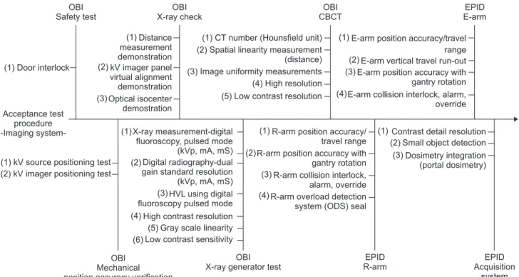
list of ATP was divided into three divisions: “Dosimetry and mechanical check” (34 items), “multi-leaf collimator” (22 items), and “imaging system” (36 items). A total of 34 items were deduced from dosimetry and mechanical checklists as shown in Fig. 3. For The MLC was subdivided into 22 items by mechanical inspection, static MLC, radiological exami- nation and dynamic MLC as shown in Fig. 4. The imaging system derives the risk management items as ATP based on the Varian linear accelerator’s on-board imager (OBI) and electronic portal imaging device (EPID). Risk management items for ATP of imaging system were classified into 21 items for OBIs and 15 items for EPIDs (Fig. 5).
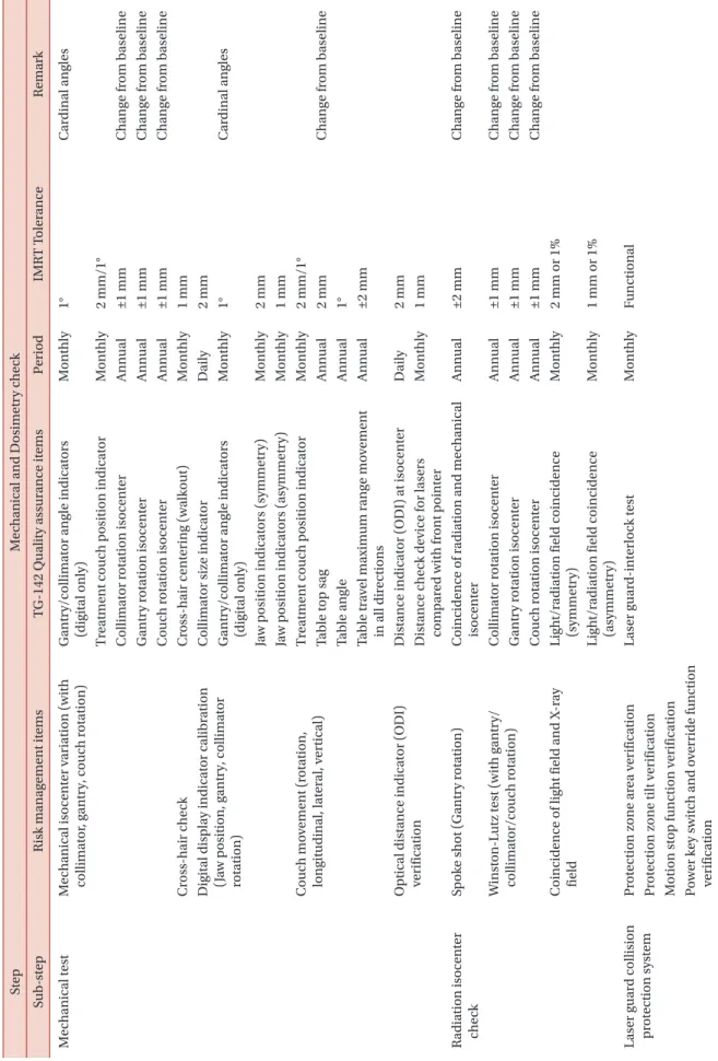
The risk management items in the derived ATP proce- dure were compared with the items listed in the AMPM TG-142 report as quality control inspection items and the IMRT recommendation criteria, and the linkages were evaluated as shown in Table 1. This is a step to confirm whether the equipment performance is in accordance with the manufacturer’s recommendation specifications from the mechanical point of view when the ATP is introduced for the first time, and it will be linked with the quality con- trol inspection item based on the reference value obtained from ATP and commissioning.
3. Commissioning of high-precision radiotherapy equipment
The risk management items in the commissioning phase were derived in detail to the performance evaluation and the clinical application evaluation of the high precision ra- diotherapy equipment, classified with preparation of beam measurement setup and beam measurement. Fig. 6 shows that the beam measurement preparation stage was 28 items, which were scanning system check, scanning system measurement preparation, and data acquisition prepara- tion. In the beam measurement, the steps are divided into X-ray scan data, X-ray point dose data, MLC data, electron scan data, electron point dose data, data file acquisition and save, and data processing. In the beam measurement stage, step-by-step procedures and risk management items of 32 were derived based on reports from overseas associa- tions such as the AAPM TG-106 report,
7)the TG-120 re- port,
10)the AAPM TG-142 report,
6)the AAPM TG-119
8)and
ESTRO booklet no. 9 report,
9)etc., as shown in Fig. 7.
The reference data for comparing measured beam data can be used as the golden data provided by the manu- facturer when conducting the beam data measurement.
However, it is not recommended to replace or combine it with the commissioning data. After measured beam data, it is recommended that measurement results and technical reports be recorded and prepared for clarity of account- ability. When creating a report, clearly describe and sum- marize the measurement range, target, method, the device used for measurement, and the results. It is recommended that CQMP check the collected data and reports and per- form independent audits. The items to be measured and the reports include X-ray open field/wedge field percent depth dose (PDD) and tissue maximum ratio (TMR) table, phantom-scatter factor (S
p), total scatter factor (S
cp), in- air scatter ratio (S
c), wedge factor and soft wedge factor for various depths and field sizes, the transmission factor, open field off-axis ratio at selected depths of large field, the electron cone factor, the effective source-to-surface distance, and the electron PDD table. It is recommended to keep the iso-dose curve and scan data measured in the reference field of X-ray and electron, and record the data comparison to similar model of the institution (or other in- stitution) or the golden data provided by the manufacturer.
It is recommended that you also back up the analyzed data, spreadsheets, electronic data, etc., and include a detailed description of the beam data collection method and condi- tions.
Commissioning data may vary depending on the re- quirements and the measurement conditions, such as the requirements of the RTP and the clinical needs of the user.
Under these conditions, the time required for commission-
ing can be expected to vary. According to the AAPM TG-
106 report, the time allocated for beam data measurement
during commissioning procedures is generally 1.5 weeks
for photon beam scanning, 1 to 2 weeks for point dose data
measurement, 1 to 2 weeks for verification and 1 to 2 weeks
for verification. It was suggested that about 4 to 6 weeks
were needed for whole commissioning.
7)For example, in
two photon energies, the time required to scan single PDD
and five depths profile for fifteen field sizes was estimated
to be about 30 hours,
7)and the time required for the elec-
Table 1.
T he der iv ed r is k m an ag emen t it ems w er e com p ar ed for the cor rel ation w ith T G-142 qualit y as sur ance it ems . St ep M ec h anic al and D os imetr y c he ck Sub- st ep R is k m an ag emen t it ems T G-142 Q ualit y as sur ance it ems P er io d IMR T T oler ance R em ar k M ec h anic al t es t M ec h anic al is ocen ter v ar ia tion (w ith collim at or , g an tr y, co uc h r ota tion) G an tr y/collim at or an gle indic at or s (di gital onl y) M on thl y 1° C ar din al an gles Tr ea tmen t co uc h p os ition indic at or M on thl y 2 mm/1° C ollim at or r ota tion is ocen ter Ann ual ±1 mm C h an ge fr om b as eline G an tr y r ota tion is ocen ter Ann ual ±1 mm C h an ge fr om b as eline C ouc h r ota tion is ocen ter Ann ual ±1 mm C h an ge fr om b as eline Cr os s-h air c he ck Cr os s-h air cen ter in g (w alk out) M on thl y 1 mm Di gital dis pl ay indic at or c alibr ation (J aw p os ition, g an tr y, collim at or rota tion)
C ollim at or s iz e indic at or D ail y 2 mm G an tr y/collim at or an gle indic at or s (di gital onl y) M on thl y 1° C ar din al an gles Ja w p os ition indic at or s (s ymmetr y) M on thl y 2 mm Ja w p os ition indic at or s (as ymmetr y) M on thl y 1 mm C ouc h mo vemen t (r ota tion, lon git udin al, l at er al, v er tic al) Tr ea tmen t co uc h p os ition indic at or M on thl y 2 mm/1° Ta ble t op s ag Ann ual 2 mm C h an ge fr om b as eline Ta ble an gle Ann ual 1° Ta ble tr av el m ax im um r an ge mo vemen t in all dir ections Ann ual ±2 mm Optic al dis tance indic at or (ODI) ver ific ation Dis tance indic at or (ODI) a t is ocen ter D ail y 2 mm Dis tance c he ck de vice for l as er s com p ar ed w ith fr on t p oin ter M on thl y 1 mm R adi ation is ocen ter ch eck Sp ok e shot (G an tr y r ota tion) C oincidence of r adi ation and me ch anic al is ocen ter Ann ual ±2 mm C h an ge fr om b as eline W ins ton-L ut z t es t (w ith g an tr y/ collim at or/co uc h r ota tion) C ollim at or r ota tion is ocen ter Ann ual ±1 mm C h an ge fr om b as eline G an tr y r ota tion is ocen ter Ann ual ±1 mm C h an ge fr om b as eline C ouc h r ota tion is ocen ter Ann ual ±1 mm C h an ge fr om b as eline C oincidence of li gh t field and X -r ay field Li gh t/r adi ation field coincidence (s ymmetr y) M on thl y 2 mm or 1% Li gh t/r adi ation field coincidence (as ymmetr y) M on thl y 1 mm or 1% Las er g uar d collis ion pr ot ection s ys tem Pr ot ection z one ar ea v er ific ation Las er g uar d-in ter lo ck t es t M on thl y Function al Pr ot ection z one tilt v er ific ation M otion s top function v er ific ation P ow er ke y sw it ch a n d ov er ri d e fun cti on ver ific ation
Table 1.
C on tin ue d 1. St ep M ec h anic al and D os imetr y c he ck Sub- st ep R is k m an ag emen t it ems T G-142 Q ualit y as sur ance it ems P er io d IMR T T oler ance R em ar k B eam p er for m ance te st P hot on P DD X -r ay b eam qualit y (P DD
10or TMR
20,10) Ann ual ±1% C h an ge fr om b as eline P hot on field fl atnes s/s ymmetr y P hot on b eam pr ofile cons tanc y M on thl y 1% X -r ay fl atnes s c h an ge fr om b as eline Ann ual 1% X -r ay s ymmetr y c h an ge fr om b as eline Ann ual ±1% E le ctr on P DI E le ctr on ener gy cons tanc y M on thl y 2%/2 mm E le ctr on b eam qualit y (R
50) Ann ual ±1 mm C h an ge fr om b as eline E le ctr on field fl atnes s/s ymmetr y E le ctr on b eam pr ofile cons tanc y M on thl y 1% E le ctr on fl atnes s c h an ge fr om b as eline Ann ual 1% E le ctr on s ymmetr y c h an ge fr om b as eline Ann ual ±1% Symmetr y in ter lo ck c he ck Follo w m an ufact ur er ’s t es t pr oce dur e Ann ual Function al B eams topp er in ter lo ck ed an gles Follo w m an ufact ur er ’s t es t pr oce dur e Ann ual Function al D os imetr y D os e r epr oducibilit y X -r ay o utp ut cons tanc y D ail y 3% All ener gies M on thl y 2% All ener gies E le ctr on o utp ut cons tanc y D ail y 3% M on thl y 2% B ac kup monit or c h am b er cons tanc y M on thl y 2% X -r ay/ele ctr on o utp ut c alibr ation ( T G-5 1) Ann ual ±1% A bs olut e dos imetr y Sp ot c he ck of field s iz e dep enden t o utp ut fact or s for X -r ay Ann ual 2% <4×4 cm
2T w o or mor e field s iz e ch eck 1% ≥4×4 cm
2O utp ut fact or s for ele ctr on a pplic at or s Ann ual ±2% - C h an ge fr om b as eline - Sp ot c he ck of on applic at or/ener gy D os e line ar it y w ith MU X -r ay monit or unit line ar it y o utp ut cons tanc y Ann ual ±2% (≥5 MU ) ±5% (2-4 MU ) E le ctr on monit or unit line ar it y o utp ut cons tanc y Ann ual ±2% (≥5 MU ) D os e line ar it y w ith dos e r at e T ypic al dos e r at e pr ofile cons tanc y M on thl y 2% X -r ay o utp ut cons tanc y vs . dos e r at e Ann ual ±2% C h an ge fr om b as eline D os e r epr oducibilit y w ith g an tr y an gle X -r ay o utp ut cons tanc y vs . g an tr y an gle Ann ual ±1% C h an ge fr om b as eline E le ctr on o utp ut cons tanc y vs . g an tr y an gle Ann ual ±1%
Table 1.
C on tin ue d 2. St ep M LC Sub- st ep R is k m an ag emen t it ems T G-142 Q ualit y as sur ance it ems P er io d IMR T T oler ance R em ar k M ec h anic al t es t Field li gh t ali gnmen t Set tin g vs . r adi ation field for t w o p at terns M on thl y 2 mm C oincidence of li gh t field and X -r ay field M on thl y ±2 mm All ener gies Cr os s-h air ali gnmen t Cr os s-h air cen ter in g (w alk out) M on thl y 1 mm G an tr y/collim at or r ota tion is ocen ter G an tr y/collim at or an gle indic at or s (di gital onl y) M on thl y 1° C ar din al an gles C ollim at or r ota tion is ocen ter Ann ual ±1 mm C h an ge fr om b as eline G an tr y r ota tion is ocen ter Ann ual ±1 mm C h an ge fr om b as eline Optic al dis tance indic at or (ODI) ver ific ation Dis tance indic at or (ODI) a t is ocen ter D ail y 2 mm Dis tance c he ck de vice for l as er s com p ar ed w ith fr on t p oin ter M on thl y 1 mm C ollim at or r ota tion r eado ut c alibr ation G an tr y/collim at or an gle indic at or s (di gital onl y) M on thl y 1° C ar din al an gles A cces sor y mo un t A cces sor y tr ay s (i.e ., p or t film gr atic le tr ay) M on thl y 2 mm La tc hin g of w ed ges , blo ck tr ay M on thl y Function al Sta tic ML C L eaf p os ition acc ur ac y Q ualita tiv e t es t (i.e ., m at che d s egmen ts , ak a “ Pic ket fence ”) W eekl y V is ual ins p ection for dis cern able de vi ations suc h as an incr eas e in in ter le af tr ansmis sion L eaf p os ition acc ur ac y M on thl y 1 mm Fo ur c ar din al an gles L eaf p os ition r ep ea ta bilit y L eaf p os ition r ep ea ta bilit y Ann ual ±1 mm R adi ation t es t C ollim at or s p ok e shot L eaf s p ok e shot Ann ual ≤1.0 mm (r adius) G an tr y s p ok e shot L eaf s p ok e shot Ann ual ≤1.0 mm (r adius) C oincidence of li gh t field and X -r ay field C oincidence of li gh t field and X -r ay field M on thl y ±2 mm All ener gies D yn amic ML C ML C tr ansmis sion dos e r at es ML C tr ansmis sion (a ver ag e of le af and in ter le af tr ansmis sion) Ann ual ±0.5% C h an ge fr om b as eline All ener gies A ut oD yn alo gs for the M illennium ML C - - - O nl y V ar ian G ener at e d yn alo gs for M ar k s er ies or m3 ML C - - - O nl y V ar ian R V mo deup - - - Ar c d yn amic le af s p ee d t es t Tr av el s p ee d M on thl y L os s of le af s p ee d>0.5 cm/s Ar c d yn amic in ter lo ck tr ip t es t Ar c mo de (E xp ect ed MU , de gr ees) Ann ual ±1 mm C h an ge fr om b as eline Ar c d yn amic t ypic al pl an t es t Ar c mo de (E xp ect ed MU , de gr ees) Ann ual ±1 mm C h an ge fr om b as eline Se gmen tal IMR T t es t (S tep and sho ot) Se gmen tal IMR T (s tep and sho ot) t es t Ann ual RMS m ax im um of er ror<0.35 cm M ovin g w indo w IMR T t es t M ovin g w indo w IMR T Ann ual RMS m ax im um of er ror<0.35 cm Fo ur c ar din al g an tr y an gles M ovin g w indo w IMR T t ypic al pl an t es t
Table 1.
C on tin ue d 3. St ep Im agin g s ys tem Sub- st ep R is k m an ag emen t it ems T G-142 Q ualit y as sur ance it ems P er io d IMR T T oler ance R em ar k O BI Safet y t es t D oor in ter lo ck - - - M ec h anic al p os ition acc ur ac y ver ific ation
kV s our ce p os itionin g t es t P os itionin g/r ep os itionin g D ail y ≤2 mm kV Im ag er p os itionin g t es t P os itionin g/r ep os itionin g D ail y ≤2 mm X -r ay c he ck Dis tance me as ur emen t demons tr ation Sc alin g M on thl y B as eline kV im ag er p anel vir tual ali gnmen t demons tr ation Im agin g and tr ea tmen t co or din at e coincidence D ail y ≤1 mm Optic al is ocen ter demos tr ation Im agin g and tr ea tmen t co or din at e coincidence D ail y ≤2 mm Sin gle g an tr y an gle M on thl y ≤2 mm Fo ur c ar din al an gles X -r ay gener at or te st
X -r ay m ea su re m en t- d ig it al fl u or os co py , p uls ed mo de (kV p, mA , mS) Im agin g dos e Ann ual B as eline Di gital r adio gr aph y-dual g ain s tand ar d res olution (kV p, mA , mS) Im agin g dos e Ann ual B as eline H V L us in g Di gital fluor os cop y p uls ed mo de B eam qualit y/ener gy Ann ual B as eline H igh con tr as t r es olution Sp ati al r es olution M on thl y B as eline Gr ay s cale line ar it y Sp ati al r es olution M on thl y B as eline L ow con tr as t s ens itivit y C on tr as t M on thl y B as eline C one b eam CT C T n um b er (H ounsfield unit) HU cons tanc y M on thl y B as eline Sp ati al line ar it y me as ur emen t (dis tance) G eometr ic dis tor tion M on thl y B as eline Im ag e unifor mit y me as ur emen ts U nifor mit y and nois e M on thl y B as eline H igh r es olution Sp ati al r es olution M on thl y B as eline L ow con tr as t r es olution C on tr as t M on thl y B as eline
Table 1.
C on tin ue d 4. St ep Im agin g s ys tem Sub- st ep R is k m an ag emen t it ems T G-142 Q ualit y as sur ance it ems P er io d IMR T T oler ance R em ar k EP ID R -ar m R -ar m p os ition acc ur ac y/tr av el r an ge P os itionin g/r ep os itionin g D ail y ≤2 mm R -ar m p os ition acc ur ac y w ith g an tr y rota tion Im agin g and tr ea tmen t co or din at e coincidence D ail y ≤2 mm Sin gle g an tr y an gle M on thl y ≤2 mm Fo ur c ar din al an gles R -ar m collis ion in ter lo ck , al ar m , ov er ride C ollis ion in ter lo ck s D ail y Function al R -ar m o ver lo ad det ection s ys tem (OD S) s eal - - - E-ar m E-ar m p os ition acc ur ac y/tr av el r an ge P os itionin g/r ep os itionin g D ail y ≤2 mm E-ar m v er tic al tr av el r un-o ut Full r an ge of tr av el S DD Ann ual ±5 mm E-ar m p os ition acc ur ac y w ith g an tr y rota tion Im agin g and tr ea tmen t co or din at e coincidence D ail y ≤2 mm Sin gle g an tr y an gle M on thl y ≤2 mm Fo ur c ar din al an gles E-ar m collis ion in ter lo ck , al ar m , ov er ride C ollis ion in ter lo ck s D ail y Function al A cquis ition sy st em C on tr as t detail r es olution Sp ati al r es olution M on thl y B as eline C on tr as t M on thl y B as eline Sm all obj ect det ection Sp ati al r es olution M on thl y B as eline D os imetr y in te gr ation (P or tal dos imetr y) - - - Option al ODI, optic al dis tance indic at or ; P DD , p er cen t depth dos e; TMR , tis sue m ax im um r atio; P DI, p er cen t depth ioniza tion; MU , monit or unit ; HU , ho unsfield unit ; S DD , s our ce-det ect or dis tance .
tron should also be considered. In addition, it has been suggested that there is a need to estimate additional time for non-scan data measurement and integration, quality
assurance baseline reading, and treatment planning sys- tem data validation. The time required for commissioning is determined by the amount of measurement data to be
Commissioning -Preparation of beam
measurement-
Scanning system check and preparation
Scanning system measurement setup (1) Water phantom materials, size, check
(2) Water phantom storage condition check (3) Check the use of solid phantom (4) Ionization chamber selection (5) Ionization chamber calibration
Preparation for data acquisition (1) Check measuring software function and
measurement conditions (2) Check the connection between the scanning system and the software
(1) Phantom positioning (2) X, Y, Z axis, labeling (3) Central axis scanner movement check (4) Zero depth check (5) Chamber shift (6) Axis alignment check (7) Phantom tilt check (8) Gantry tilt check (9) Cable connector type check (10) Check cables, connectors and adapter connection error factors
(11) Cable and connector leakage check (12) Mount on field and reference chamber
(13) Check the measurement performance after calibration of the ionization chamber
(14) Ionization chamber effective depth check (15) Electrometer polarity effect check (16) Check for electrometer leakage current (17) Check electrometer measurement performance (18) Scan speed with ionization chamber movement (19) Check for ionization chamber position accuracy and
hysteresis
(20) Block potential collisions when moving the ionization chamber
Fig. 6. The risk management items for commissioning of external radiation therapy equipment: preparation of beam measurement.
Commissioning -Beam measurement-
X-ray scan data and point dose
measurement
MLC data (1) PDD measurement (SSD=100 cm or 90 cm)
(2) Conversion between PDD taken at different SSD (3) Extended distance (SSD>100 cm) beam data (4) TMR or TPR measurement (5) Surface dose and buildup region check (6) Beam profiles measurement (7) Physical wedge field measurement (8) Total scatter factor (S ), In-air output ratio (S ), and phantom scatter factor (S )
cp c
p
(9) Wedge factors and tray factors (10) Small field dosimetry
Electron scan data and point dose measurement
(1) Coincidence of light field and X-ray field (2) Interleaf leakage (leakage between two leaves) (3) Intraleaf leakage (transmission though a leaf) (4) Tongue and grove effect (5) Penumbra (6) Dosimetric leaf gap check
Data processing
(1) Smoothing (2) Mirroring (3) Mathematical functions and filters (1) PDI measurement (SSD=100 cm)
(2) Extended distance (SSD>100 cm) beam data (3) Beam profiles measurement (4) Cone factors and cut-out factors (5) Virtual and effective source position (6) Dose calculation using Monte Carlo approaches
Data file acquisition and save (1) Data file organization
(2) File name (3) Confirming constraints on the software function used in the measurement
Fig. 7. The risk management items for commissioning of external radiation therapy equipment: beam measurement.