placement: a prospective clinical study
Mario Beretta, Pier Paolo Poli*, Carlo Maiorana
Department of Dental Implants, U.O.C. Maxillofacial Surgery and Odontostomatology, Fondazione IRCCS Cà Granda, State University of Milan, Milan, Italy
Research Article
J Periodontal Implant Sci 2014;44:184-193 http://dx.doi.org/10.5051/jpis.2014.44.4.184
Purpose: The aim of the present study was to evaluate the in vivo accuracy of flapless, computer-aided implant placement by comparing the three-dimensional (3D) position of planned and placed implants through an analysis of linear and angular deviations.
Methods: Implant position was virtually planned using 3D planning software based on the functional and aesthetic requirements of the final restorations. Computer-aided design/
computer-assisted manufacture technology was used to transfer the virtual plan to the surgical environment. The 3D position of the planned and placed implants, in terms of the linear deviations of the implant head and apex and the angular deviations of the implant axis, was compared by overlapping the pre- and postoperative computed tomography scans using dedicated software.
Results: The comparison of 14 implants showed a mean linear deviation of the implant head of 0.56 mm (standard deviation [SD], 0.23), a mean linear deviation of the implant apex of 0.64 mm (SD, 0.29), and a mean angular deviation of the long axis of 2.42° (SD, 1.02).
Conclusions: In the present study, computer-aided flapless implant surgery seemed to pro- vide several advantages to the clinicians as compared to the standard procedure; however, linear and angular deviations are to be expected. Therefore, accurate presurgical planning taking into account anatomical limitations and prosthetic demands is mandatory to ensure a predictable treatment, without incurring possible intra- and postoperative complications.
Keywords: Computer-aided design, Dental implants, X-ray computed tomography.
Received: Jun. 23, 2014 Accepted: Jul. 23, 2014
*Correspondence:
Pier Paolo Poli
Department of Dental Implants, U.O.C.
Maxillofacial Surgery and Odontostomatology, Fondazione IRCCS Cà Granda, State University of Milan, Via Commenda 10, Milan 20122, Italy E-mail: [email protected]
Tel: +390255032621 Fax: +390255032513
INTRODUCTION
In the past, implant positions were determined by the amount of bone anatomically present, with less consideration to the final prosthesis. However, neglecting prosthetic de- mands often led to an unfavourable prosthesis with a compromised occlusal scheme, poor aesthetics, and/or unfavourable biomechanics [1-3]. Widely accepted reconstructive tech- niques, including sinus augmentation, distraction osteogenesis, bone splitting, bone graft- ing techniques, and tissue regeneration [4-8], have allowed clinicians to develop the recent philosophy of prosthetic-driven implant placement, combining functional and aesthetic concepts. The positions of the proposed implants are planned on the basis of diagnostic casts and wax-ups of the prosthodontic restoration. Customized radiographic and surgical templates have become essential for transferring the virtual plan to the surgical field [9- 12]. This approach was made possible by the use of computed tomography (CT) scans inte-
This is an Open Access article distributed under the terms of the Creative Commons Attribution Non-Commercial License (http://creativecommons.org/licenses/by-nc/3.0/).
grated with three-dimensional (3D) virtual planning software, and computer-aided design/computer-assisted manufacture (CAD/
CAM) technology. Heretofore, three practical ways to transfer the virtually planned implant position to the clinical situation could be found in the literature: guided surgery using drill guides processed by stereolithographic rapid prototyping [13-17], computer-milled templates [18-20], and computer navigation systems [21]. Howev- er, it is beyond the scope of this study to evaluate the accuracy of computer-milled templates or computer navigation systems. Sev- eral advantages of computer-aided oral implant surgery have been reported, including: (1) flapless surgery with a consequent decrease in surgical time and patient morbidity; (2) preservation of soft tis- sue structure and hard tissue volume in the surgical site; (3) inte- gration of the restorative determinants into the surgical planning, resulting in a more aesthetic, functional, and predictable prosthetic outcome; and (4) simplification of the technique-sensitive and op- erator-dependent surgical procedure [22]. However, this technique is not free of drawbacks, some of which are as follows: (1) the sur- geon’s inability to visualize anatomic structures; (2) the increased risk of axis and depth deviations during implant placement; an (3) a decreased ability to contour the jawbone topography when needed for prosthetic purposes [23]. In order to evaluate the accu- racy of computer-aided implant placement systems as an index of safety and effectiveness, the literature is unanimous in assessing specific parameters between planned and actual implant positions, namely the linear deviation of the implant head and apex and the angular deviation of the implant long axis. However, the results found in the literature are heterogeneous. In general, better out- comes were reported in in vitro or ex vivo studies [17,24], probably due to better access, better visual control of the osteotomy axis, and the absence of movement, saliva, and blood in the preclinical models [25]. Consequently, it is a general opinion that in vitro and cadaver studies may overestimate accuracy and underestimate er- ror [22]. When considering in vivo studies, higher values in mea- surements confirmed the better outcomes as stated [25,26]. Com- puter-aided surgery has been advocated for clinical situations pre- senting a limited quantity of bone, frequently characterized by critical anatomical situations. Therefore, the potential maximal im- plant deviations of the system have to be reduced to a minimum.
This is enabled by the reproducibility and the stability of the tem- plate position during the acquisition of digital imaging and com- munications in medicine (DICOM) data, and during implantation, particularly in edentulous patients. Intraoral or extraoral radi- opaque markers are generally used for transferring anatomical and prosthetic information into 3D virtual planning software. A surgi- cal template is subsequently realized, generally supported by the bone, the mucosa, and/or the remaining teeth. The aim of the present study was to evaluate the in vivo accuracy of a novel com- puter-aided, template-guided flapless treatment protocol, in which the attention was focused on the possibility of improving system precision at each step from planning to surgery. Unlike the others, the present system envisaged a new double scanning procedure to
integrate anatomical data into a virtual environment. A rapid pro- totyping procedure was used to realize a surgical guide, which was stabilized in an appropriate position by means of a silicon index and fixed to the jaw with bone pins. The accuracy was assessed by comparing the 3D positions of planned and placed implants in terms of the linear deviations of the implant head and apex and the angular deviations of the implant axis. Linear deviations be- tween the virtual and the actual position of the barycentre coordi- nates of the surgical template were also calculated.
MATERIALS AND METHODS
Two patients treated at the Department of Dental Implants, U.O.C. Maxillofacial Surgery and Odontostomatology, Fondazione IRCCS Cà Granda, University of Milan (Italy), in February 2013 with computer-aided, template-guided flapless implant surgery, were included in the present prospective clinical study. Only two pa- tients were enrolled in the present pilot study to evaluate the ac- curacy of the system before extending the protocol to a larger number of cases. The 3Diagnosys data software (3Diemme, Como, Italy) was used to plan the correct implant position and to transfer the project to the surgical environment, allowing the correct real- ization of a surgical stent. The postoperative accuracy analysis was conducted with the same software. Informed consent was ob- tained from the subjects.
Inclusion and exclusion criteria
Patients demonstrating good general health with no local or systemic contraindications to oral surgery and implant placement were considered in the study. Inclusion criteria were both partial and total edentulism in which the teeth were lost at least two months before the date of implant placement, characterized by an adequate quantity of bone, assessed as a minimum of 1 mm buc- cally and palatally/lingually, and associated with at least 3 mm of keratinized gingiva around the implant.
Exclusion criteria were poor oral hygiene, active periodontal in- fections, uncontrolled systemic pathologies, and presence of a smoking habit (>10 cigarettes/day). Anatomical situations requir- ing regenerative procedures prior or contemporaneous to the im- plant surgery were excluded.
Therapeutic protocol
The patients underwent the same treatment protocol, which in- cluded the following steps:
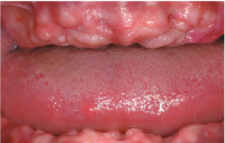
(1) Preoperative CT scan and panoramic exam, and clinical eval- uation (Fig. 1) in order to confirm the possibility of perform- ing the implant insertion without any grafting procedure.
(2) Evaluation of the articulated chalk models and realization of a preliminary prosthetic wax-up, corresponding to the exact replica of the definitive prosthesis accepted by the patient, integrated with aesthetic and functional principles.
(3) Realization of a radiological stent on the basis of the prelimi-
nary prosthetic wax-up, as a duplication of the final prosthe- sis. The radiological stent was equipped with an extraoral ra- diopaque marker for 3D position tracking, required for the
subsequent scan overlapping.
(4) CT scan of the edentulous jaw while the patient was using the provisory radiopaque stent to integrate the anatomic data with the functional and aesthetic parameters, and opti- cal scan of the prosthesis itself, as needed by the 3Diagnosys data software.
(5) Importation and matching of the two different scans within the software and 3D virtual implant position planning with the 3Diagnosys data software according to the jawbone anatomy and the prosthetic design. This was enabled by the processing of the stereolithography interface (STL)-format data acquired from the optical scan overlapping the data ob- tained from the CT device in a DICOM format, which allowed simultaneous viewing of the axial, 3D, panoramic, and cross- sectional images on the computer monitor (Figs. 2 and 3).
(6) Transferral of the virtual project to a 1:1 scale model (XLTEK RealPATIENT, Excel Tech Ltd., Oakville, ON, Canada) with a rap- id prototyping technique, and subsequent realization of a sur- Figure 1. Preoperative frontal view of the edentulous jaws.
Figure 3. Computer-aided planning in the lower jaw.
Figure 2. Computer-aided planning in the upper jaw.
gical stent obtained according to the CT scans and preopera- tory chalk models by using the principle of stereolithography.
(7) Computer-aided, template-guided flapless implant place- ment according to the manufacturer’s instructions (Camlog Guide System, Camlog Biotechnologies, Basel, Switzerland).
Surgical procedure
All surgical procedures were performed by the same surgeon on an outpatient basis. The surgical guide was previously prepared by means of chemical sterilization by ethylene oxide. An antibiotic prophylaxis consisting of 2 g of amoxicillin clavulanate (Augmentin, GlaxoSmithKline S.p.A., Verona, Italy) was administered 1 hour be- fore surgery. After bacterial decontamination with a 0.2% chlorhex- idine (Dentosan, Recordati S.p.A., Milan, Italy) rinsing solution and intramuscular injections of 4 mg/mL of dexamethasone sodium phosphate (Soldesam, Laboratorio Farmacologico Milanese, Varese, Italy) to reduce postoperative oedema, local anaesthesia infiltrations were performed with carbocaine 2% with epinephrine 1:100.000 (AstraZeneca S.p.A., Milan, Italy). The surgical stent was then se- cured in an appropriate position using a silicone index, with guided insertion of surgical pins on the buccal side of the alveolar process according to the virtual plan in order to preserve anatomic struc- tures (Fig. 4). The surgical stent allowed the use of different-sized
burs, switching the metallic cylinders contained in the said stents.
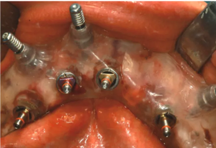
Thus, greater accuracy of implant placement was obtained, with a low risk of inappropriate insertion. A circular disposable mucosal operculectomy was performed with a surgical mucotome to remove the gingival plug from the implant site, followed by serial osteoto- mies performed using a disposable internal coolant predrill and subsequent disposable internal coolant form-drills, until the planned depth was reached. It was then possible to place the im- plants (Screw-line Camlog Guide, Promote Plus, Camlog Biotech- nologies, Basel, Switzerland) in the desired position according to the manufacturer’s instructions (Figs. 5 and 6). After removal of the pins and the surgical template, 100 mg of oral nimesulide (Aulin, Helsinn Birex Pharmaceuticals Ltd., Dublin, Ireland) was administered for pain relief.
(1) Postoperative CT scan, conducted with the same apparatus and settings as the preoperative scans.
(2) The preoperative and postoperative scans were then over- lapped using a dedicated algorithm, which allowed the com- parison of the virtually planned and the actual implant posi- tions. Three deviation parameters between each planned and placed implant were measured: linear deviations of the head
Figure 4. Stabilization of the two surgical stent by means of a silicone index.
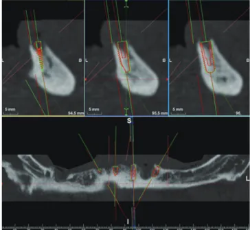
Figure 7. Overlapping of the pre- and postoperative scans for the comparison between planned (red) and real (green) implant positions in order to analyse the accuracy of the system in the upper jaw.
Figure 6. Lower surgical stent fixed in the proper position by means of corti- cal pins and implants insertion.
Figure 5. Upper surgical stent fixed in the proper position by means of corti- cal pins and implants insertion.
and apex, and angular deviations of the axis. All measure- ments were performed using dedicated software (3Diagnosys data software) (Figs. 7-10).
(3) The final prosthesis was placed after 6 months (Fig. 11), and a follow-up orthopantomograph was performed (Fig. 12).
RESULTS
A total of 14 dental implants (Screw-line Camlog Guide, Pro- mote Plus) placed in 2 fully edentulous adults were evaluated.
Each patient was treated in both arches. During postoperative healing, the implants achieved successful osseointegration, and the healing was uneventful, with neither major complications (i.e., nerve injuries, allergic reactions, sinus pathologies, and infections) Figure 9. Overlapping of the pre and postoperative scans for the comparison between planned (red) and real (green) implant positions in order to analyse the accuracy of the system in the lower jaw.
Figure 10. Accuracy assessments in the lower jaw between planned (red) and real (green) implant positions.
Figure 8. Accuracy assessments in the upper jaw between planned (red) and real (green) implant positions.
Figure 11. Frontal view of the final upper and lower restorations.
Figure 12. Follow-up X-rays control.
nor dropouts. Radiological and clinical exams showed appropriate implant stability and good healing of soft tissues during the fol- low-up recalls performed every three months. Accuracy evalua- tions were performed on all the osseointegrated implants. The comparison of planned and placed implant positions showed a
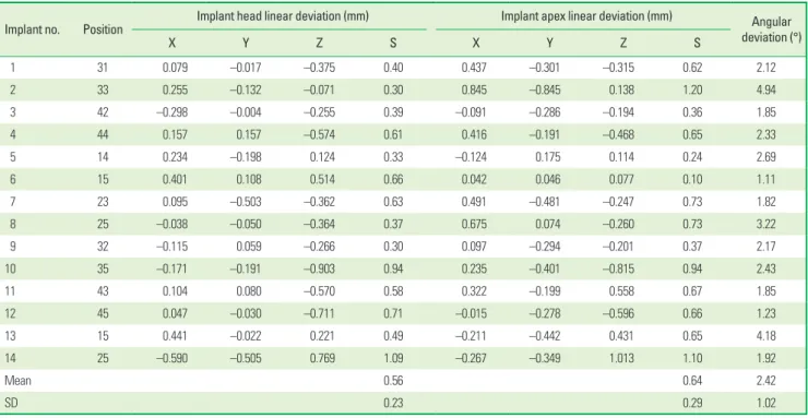
mean linear deviation of the implant head of 0.56 mm (standard deviation [SD], 0.23), a mean linear deviation of the implant apex of 0.64 mm (SD, 0.29), and a mean angular deviation of the long axis of 2.42° (SD, 1.02) (Table 1). With respect to the barycentric coordinate deviations, the results showed a mean linear deviation Table 1. Results of the comparison between planned and placed implant position in terms of implant’s head and apex linear deviation and implant’s axis angu- lar deviation, obtained by overlapping the pre- and postoperative computed tomography (CT) scans.
Implant no. Position Implant head linear deviation (mm) Implant apex linear deviation (mm) Angular
deviation (°)
X Y Z S X Y Z S
1 31 0.079 –0.017 –0.375 0.40 0.437 –0.301 –0.315 0.62 2.12
2 33 0.255 –0.132 –0.071 0.30 0.845 –0.845 0.138 1.20 4.94
3 42 –0.298 –0.004 –0.255 0.39 –0.091 –0.286 –0.194 0.36 1.85
4 44 0.157 0.157 –0.574 0.61 0.416 –0.191 –0.468 0.65 2.33
5 14 0.234 –0.198 0.124 0.33 –0.124 0.175 0.114 0.24 2.69
6 15 0.401 0.108 0.514 0.66 0.042 0.046 0.077 0.10 1.11
7 23 0.095 –0.503 –0.362 0.63 0.491 –0.481 –0.247 0.73 1.82
8 25 –0.038 –0.050 –0.364 0.37 0.675 0.074 –0.260 0.73 3.22
9 32 –0.115 0.059 –0.266 0.30 0.097 –0.294 –0.201 0.37 2.17
10 35 –0.171 –0.191 –0.903 0.94 0.235 –0.401 –0.815 0.94 2.43
11 43 0.104 0.080 –0.570 0.58 0.322 –0.199 0.558 0.67 1.85
12 45 0.047 –0.030 –0.711 0.71 –0.015 –0.278 –0.596 0.66 1.23
13 15 0.441 –0.022 0.221 0.49 –0.211 –0.442 0.431 0.65 4.18
14 25 –0.590 –0.505 0.769 1.09 –0.267 –0.349 1.013 1.10 1.92
Mean 0.56 0.64 2.42
SD 0.23 0.29 1.02
X: X-axis deviation, Y: Y-axis deviation, Z: Z-axis deviation, S: displacement vector; SD: standard deviation.
Table 2. Results of comparison between planned and placed barycentric coordinates.
Implant no. Position
Planned barycentric coordinates of
surgical stent (mm) Placed barycentric coordinates of
surgical stent (mm) Deviation
(mm)
X Y Z X Y Z S
1 31 –3.99 –55.92 10.08 –3.76 –56.14 9.81 0.41
2 33
3 42
4 44
5 14 5.06 –60.07 –44.13 5.45 –60.22 –44.19 0.43
6 15
7 23
8 25
9 32 2.85 –67.03 11.03 2.91 -67.18 10.46 0.60
10 35
11 43
12 45
13 15 3.55 –57.44 –22.91 3.36 –57.78 –22.29 0.73
14 25
X: X-axis deviation; Y: Y-axis deviation; Z:-Z axis deviation; S: displacement vector.
of 0.58 mm (SD, 0.15) in the upper jaw, and 0.50 mm (SD, 0.09) in the lower jaw (Table 2). A statistical analysis could not be per- formed due to the small size of the sample enrolled in the present preliminary study.
DISCUSSION
Traditional guidelines proposed for osseointegrated dental im- plantation contemplate a flap approach characterized by the re- flection of a mucoperiosteal flap, which requires postsurgical su- tures to seal the surgical wound. This procedure, irrespective of im- mediate loading, has shown to be successful, reporting good re- sults [27,28]. However, this approach is not free of drawbacks, in- cluding loss of the alveolar bone crest and aesthetically displeasing gingival recessions due to decreased supraperiosteal blood supply resulting from the raising of the mucosal flap during the surgical procedure, postoperative blood loss and haemorrhages, increased morbidity, and discomfort for the patient [29,30]. Flapless surgery has been recently advocated to prevent such negative effects. Ac- cording to literature [31], clinical cases such as ours, when treated with a flapless approach, have shown certain advantages, namely reduced patient swelling and pain, reduced intraoperative bleeding and surgical time, and no need for suturing, with the preservation of the soft tissue architecture and hard tissue volume at the im- plant site and maintenance of appropriate blood supply, thereby allowing the patient to restore normal oral hygiene procedures im- mediately afterwards. However, according to Sclar [32], there are several prerequisites of which surgeons must be aware in order to achieve better results with flapless surgery. The method is indicat- ed for patients with sufficient underlying alveolar bone height, volume, and density, and with an adequate or augmentable at- tached gingiva (at least 3 mm in the apico-coronal dimension) preferably keratinized, and circumferentially adapted to the trans- mucosal implant structures. In our cases, following the above- mentioned inclusion criteria allowed a prosthetically driven im- plant placement, which also takes into consideration aesthetic soft tissue requirements. The development of more accurate 3D plan- ning programs for the CT scan analysis and virtual planning con- tributed to the progress of this type of surgery and implant reha- bilitation with a one- or two-stage approach. Multiplanar refor- matting technology associated with CAD planning software allows the clinicians to virtually plan the location, angle, depth, and di- ameter of the virtual implants on the basis of the diagnostic casts and by using wax-ups as an exact replica of the final prosthesis.
Although this technique was originally developed to reduce the risks involved during standard implant procedures, providing greater control of the system, the problem of deviation between the planned and the placed implant positions still occurs.
In the present pilot study, promising results have emerged, showing a mean linear deviation of the implant head of 0.56 mm (SD, 0.23), a mean linear deviation of the implant apex of 0.64 mm (SD, 0.29), and a mean angular deviation of the long axis of 2.42°
(SD, 1.02), based on a total of 14 osseointegrated dental implants.
When the values obtained were compared with human cadaver studies, better results could be found in vivo. Van Assche et al. [17]
reported a mean hex deviation of 1.1±0.7 mm, a mean tip devia- tion of 2.0 ±0.7 mm, and a mean angular deviation of 2.0 ±0.8 mm; Pettersson et al. [33] found a mean measurement difference of 1.06 mm for the hex, 1.25 mm for the apex, and 2.64° for the angular deviation; and Widmann et al. [34] reported a mean ± standard deviation total error (Euclidean distance)/lateral error (normal deviation) of 1.1±0.6/0.7±0.5 mm at the implant base and 1.2±0.7/0.9±0.7 mm at the implant tip. The mean angular error was 2.8°±2.21°. The authors agree that the results could be a consequence of a better anchorage of the surgical template to in- tact structures. Furthermore, Pettersson et al. [33] found difficul- ties in positioning the guides in an appropriate position, since the templates had to be manually placed using rubber bands, thereby introducing plausible positioning errors. Lastly, the cadaver preser- vation techniques may have caused dehydration and a change in the size and shape of the soft tissues, in addition to bone soften- ing due to the demineralization effect of formalin [17].
When the results obtained from the present study were com- pared with those reported in other clinical studies, interesting dis- cussion points arose. In particular, values were lower when com- pared with the results obtained in recent reviews: Schneider et al.
[35] found a mean deviation of 1.16 mm at the entry point, 1.96 mm at the apex, and a mean angulation error of 5.73° when con- sidering 155 sites in three human studies; D’haese et al. [24] re- ported a mean coronal deviation of 1.04 mm, a mean apical devia- tion of 1.64 mm, and a mean angular deviation of 3.54° when an- alysing six in vivo studies; Tahmaseb et al. [26] evaluated 14 clini- cal studies in which the accuracy was assessed over a total of 2,355 implants. The lowest and the highest mean error at the entry point was 0.15 and 1.7 mm, with minimum and maximum values of 0 and 4.5 mm, respectively. The mean apical deviation varied from 0.28 to 2.99 mm, with a minimum and maximum of 0.3 and 7.1 mm, respectively. The mean angular deviation ranged from 1.49°
to 8.54° with a minimum and maximum of 0° and 21.16°, respec- tively. It was the authors’ opinion that the lower values and stan- dard deviations obtained in the present pilot study were due to several intrinsic differences in the described protocol.
Firstly, one of the critical factors in achieving good results is the correct transfer of the radiographic template into the software in order to integrate the prosthesis plan and the patient anatomy into the 3D virtual planning. This is enabled by the use of intraoral or extraoral radiopaque reference points. Traditionally, orally situ- ated gutta-percha or acrylic and barium-sulphate markers are em- ployed as radiopaque material, thereby allowing clinicians to transfer the desired implant position into the planning software.
With this procedure, Van Assche et al. [36] reported a mean angu- lar deviation of the long axis between the planned and the placed implants of 2.71°, with a mean horizontal deviation of 0.7 mm at the neck and 1.0 mm at the apex; Ozan et al. [37] found a mean
angular deviation of 4.1°±2.3°, whereas the mean linear deviation was 1.11±0.7 mm at the implant neck and 1.41±0.9 mm at the implant apex as compared to the planned implants; similar results were reported by Ersoy et al. [23], with a mean angular deviation of 4.9°±2.36°, a mean linear deviation of 1.22±0.85 mm at the implant neck, and 1.51±1 mm at the implant apex. As highlighted by Widmann and Bale [38], the negative consequence of intraoral markers (invasive or template-supported) is that, in extended pros- thetic restorations with fixed partial dentures or dental crowns, the presence of metallic artefacts may lead to difficulties in marker identification and precise transferral of the virtual planning to the surgical site. Therefore, the better results obtained in the present study were probably due to the fact that an extraoral radiopaque marker had been used, namely a well-defined geometric device in which a total of 300,000 points were scanned and overlapped dur- ing the matching procedure within the planning software, allow- ing a greater accuracy in the superimposition of the DICOM data and radiological stent as compared to standard protocols in which only a limited number of reference points are used. Furthermore, most of the studies contemplated a double scanning procedure, in which both the patient and the radiological template were sub- jected to a CT scan [36,39,40]. In contrast, in the present study, the radiological stent underwent an optical scan, providing STL data that, unlike with the CT scan, did not depend on the Hounsfield unit threshold based on the grey-level segmentation defined by the radiologist. The accuracy of the patient’s virtual anatomy was therefore enhanced as it originated from the more precise data obtained with the optical scan instead of the CT scan. This allowed the clinician to establish the soft tissue thickness exactly, resulting in more accurate virtual planning.
Another prerequisite for achieving an optimal accuracy level is the fixation of the stereolithographic surgical template in the sur- gical site. Several stents had been developed, such as bone-sup- ported, mucosa-supported, or teeth-supported. While dental- and mucosal-supported guides can be useful in flapless surgery tech- niques, the use of a bone-supported guidance system requires flap surgery. In order to improve the stability of the system, the use of anchor pins inserted into the jawbone has been advocated to pre- vent micromovements of the surgical guides, which could jeopar- dize accuracy. In a comparison of the results of the present study with others in which the use of anchor pins was not mentioned, better results were obtained with the use of stabilizing devices. In particular, Di Giacomo et al. [13] found an implant axis deviation within 7.25° ±2.67°; the differences in distance between the planned and the placed positions at the implant shoulder were 1.45±1.42 mm, and 2.99±1.77 mm at the implant apex; further, Ozan et al. [37] and Ersoy et al. [23] showed higher deviations, as listed before. According to Cassetta et al. [39], it was found that the use of three osteosynthesis screws, placed in a tripod forma- tion, was sufficient to provide the necessary stability, thereby im- proving the system accuracy. Furthermore, unlike bone screws, bone pins were guided into dedicated sleeves with a limited
planned depth, in order to prevent surgical template deformations caused by excessive fixing pressures.
Finally, the disposable drills used in the present protocol may have improved the accuracy of the system, thereby enhancing the cutting potential and consequently preventing possible deviations originating from excessive wear. The limited sample size did not al- low final statements to be made; however, it was the authors’
opinion that flapless computer-aided implant surgery provided cli- nicians with undeniable advantages. The flapless approach allowed the surgeon to minimize surgical trauma and patient morbidity in the immediate postoperative period. At the same time, computer- aided surgery reduced the possibility of intraoperative complica- tions, further permitting an ideal prosthetic-driven implant place- ment. The results of the present preliminary study showed that lin- ear deviations above 1 mm and angular deviations above 4° were somewhat rare; however, even with the use of a stereolithographic surgical guide, it is always advisable, in our opinion, to maintain a minimum safety distance from the surrounding anatomical struc- tures of at least 2 mm. Following meticulous presurgical planning and respecting the safety distances, we find that the placement of dental implants with this technique becomes is a reliable and pre- dictable procedure; however, it still requires high levels of experi- ence and therefore, should not be considered a routine procedure.
CONFLICT OF INTEREST
No potential conflict of interest relevant to this article was re- ported.
ORCID
Mario Beretta http://orcid.org/0000-0002-2223-2553 Pier Paolo Poli http://orcid.org/0000-0003-3739-1490 Carlo Maiorana http://orcid.org/0000-0001-8748-9483
REFERENCES
1. Rangert B, Krogh PH, Langer B, Van Roekel N. Bending overload and implant fracture: a retrospective clinical analysis. Int J Oral Maxillofac Implants 1995;10:326-34.
2. Hobkirk JA, Havthoulas TK. The influence of mandibular defor- mation, implant numbers, and loading position on detected forc- es in abutments supporting fixed implant superstructures. J Pros- thet Dent 1998;80:169-74.
3. Stanford CM. Biomechanical and functional behavior of im- plants. Adv Dent Res 1999;13:88-92.
4. Schwartz-Arad D, Levin L. Intraoral autogenous block onlay bone grafting for extensive reconstruction of atrophic maxillary alve- olar ridges. J Periodontol 2005;76:636-41.
5. Maiorana C, Santoro F. Maxillary and mandibular bone recon- struction with hip grafts and implants using Frialit-2 implants.
Int J Periodontics Restorative Dent 2002;22:221-9.
6. Simion M, Trisi P, Piattelli A. Vertical ridge augmentation using a membrane technique associated with osseointegrated implants.
Int J Periodontics Restorative Dent 1994;14:496-511.
7. Chiapasco M, Lang NP, Bosshardt DD. Quality and quantity of bone following alveolar distraction osteogenesis in the human mandible. Clin Oral Implants Res 2006;17:394-402.
8. Engelke WG, Diederichs CG, Jacobs HG, Deckwer I. Alveolar re- construction with splitting osteotomy and microfixation of im- plants. Int J Oral Maxillofac Implants 1997;12:310-8.
9. Becker CM, Kaiser DA. Surgical guide for dental implant place- ment. J Prosthet Dent 2000;83:248-51.
10. Almog DM, Torrado E, Meitner SW. Fabrication of imaging and surgical guides for dental implants. J Prosthet Dent 2001;85:
504-8.
11. Garber DA. The esthetic dental implant: letting restoration be the guide. J Am Dent Assoc 1995;126:319-25.
12. Pesun IJ, Gardner FM. Fabrication of a guide for radiographic evaluation and surgical placement of implants. J Prosthet Dent 1995;73:548-52.
13. Di Giacomo GA, Cury PR, de Araujo NS, Sendyk WR, Sendyk CL.
Clinical application of stereolithographic surgical guides for im- plant placement: preliminary results. J Periodontol 2005;76:503-7.
14. Sarment DP, Al-Shammari K, Kazor CE. Stereolithographic surgi- cal templates for placement of dental implants in complex cases.
Int J Periodontics Restorative Dent 2003;23:287-95.
15. van Steenberghe D, Naert I, Andersson M, Brajnovic I, Van Cleynenbreugel J, Suetens P. A custom template and definitive prosthesis allowing immediate implant loading in the maxilla: a clinical report. Int J Oral Maxillofac Implants 2002;17:663-70.
16. Sarment DP, Sukovic P, Clinthorne N. Accuracy of implant place- ment with a stereolithographic surgical guide. Int J Oral Maxillo- fac Implants 2003;18:571-7.
17. Van Assche N, van Steenberghe D, Guerrero ME, Hirsch E, Schutys- er F, Quirynen M, et al. Accuracy of implant placement based on pre-surgical planning of three-dimensional cone-beam images: a pilot study. J Clin Periodontol 2007;34:816-21.
18. Fortin T, Champleboux G, Lormee J, Coudert JL. Precise dental im- plant placement in bone using surgical guides in conjunction with medical imaging techniques. J Oral Implantol 2000;26:300-3.
19. Fortin T, Champleboux G, Bianchi S, Buatois H, Coudert JL. Preci- sion of transfer of preoperative planning for oral implants based on cone-beam CT-scan images through a robotic drilling ma- chine. Clin Oral Implants Res 2002;13:651-6.
20. Klein M, Abrams M. Computer-guided surgery utilizing a com- puter-milled surgical template. Pract Proced Aesthet Dent 2001;
13:165-9.
21. Widmann G, Widmann R, Widmann E, Jaschke W, Bale R. Use of a surgical navigation system for CT-guided template production.
Int J Oral Maxillofac Implants 2007;22:72-8.
22. Valente F, Schiroli G, Sbrenna A. Accuracy of computer-aided oral implant surgery: a clinical and radiographic study. Int J Oral Maxillofac Implants 2009;24:234-42.
23. Ersoy AE, Turkyilmaz I, Ozan O, McGlumphy EA. Reliability of im- plant placement with stereolithographic surgical guides generat- ed from computed tomography: clinical data from 94 implants. J Periodontol 2008;79:1339-45.
24. D'haese J, Van De Velde T, Komiyama A, Hultin M, De Bruyn H.
Accuracy and complications using computer-designed stereo- lithographic surgical guides for oral rehabilitation by means of dental implants: a review of the literature. Clin Implant Dent Relat Res 2012;14:321-35.
25. Jung RE, Schneider D, Ganeles J, Wismeijer D, Zwahlen M, Ham- merle CH, et al. Computer technology applications in surgical implant dentistry: a systematic review. Int J Oral Maxillofac Im- plants 2009;24 Suppl:92-109.
26. Tahmaseb A, Wismeijer D, Coucke W, Derksen W. Computer tech- nology applications in surgical implant dentistry: a systematic review. Int J Oral Maxillofac Implants 2014;29 Suppl:25-42.
27. De Bruyn H, Atashkadeh M, Cosyn J, van de Velde T. Clinical out- come and bone preservation of single TiUnite™ implants installed with flapless or flap surgery. Clin Implant Dent Relat Res 2011;
13:175-83.
28. Jensen OT, Cullum DR, Baer D. Marginal bone stability using 3 different flap approaches for alveolar split expansion for dental implants: a 1-year clinical study. J Oral Maxillofac Surg 2009;67:
1921-30.
29. Wood DL, Hoag PM, Donnenfeld OW, Rosenfeld LD. Alveolar crest reduction following full and partial thickness flaps. J Peri- odontol 1972;43:141-4.
30. Rousseau P. Flapless and traditional dental implant surgery: an open, retrospective comparative study. J Oral Maxillofac Surg 2010;68:2299-306.
31. Brodala N. Flapless surgery and its effect on dental implant out- comes. Int J Oral Maxillofac Implants 2009;24 Suppl:118-25.
32. Sclar AG. Guidelines for flapless surgery. J Oral Maxillofac Surg 2007;65(7 Suppl 1):20-32.
33. Pettersson A, Kero T, Gillot L, Cannas B, Faldt J, Soderberg R, et al. Accuracy of CAD/CAM-guided surgical template implant sur- gery on human cadavers: Part I. J Prosthet Dent 2010;103:334- 42.
34. Widmann G, Zangerl A, Keiler M, Stoffner R, Bale R, Puelacher W.
Flapless implant surgery in the edentulous jaw based on three fixed intraoral reference points and image-guided surgical tem- plates: accuracy in human cadavers. Clin Oral Implants Res 2010;
21:835-41.
35. Schneider D, Marquardt P, Zwahlen M, Jung RE. A systematic re- view on the accuracy and the clinical outcome of computer- guided template-based implant dentistry. Clin Oral Implants Res 2009;20 Suppl 4:73-86.
36. Van Assche N, van Steenberghe D, Quirynen M, Jacobs R. Accu- racy assessment of computer-assisted flapless implant placement in partial edentulism. J Clin Periodontol 2010;37:398-403.
37. Ozan O, Turkyilmaz I, Ersoy AE, McGlumphy EA, Rosenstiel SF.
Clinical accuracy of 3 different types of computed tomography-
derived stereolithographic surgical guides in implant placement.
J Oral Maxillofac Surg 2009;67:394-401.
38. Widmann G, Bale RJ. Accuracy in computer-aided implant sur- gery: a review. Int J Oral Maxillofac Implants 2006;21:305-13.
39. Cassetta M, Stefanelli LV, Giansanti M, Di Mambro A, Calasso S.
Depth deviation and occurrence of early surgical complications
or unexpected events using a single stereolithographic surgi- guide. Int J Oral Maxillofac Surg 2011;40:1377-87.
40. D'haese J, Van De Velde T, Elaut L, De Bruyn H. A prospective study on the accuracy of mucosally supported stereolithographic surgical guides in fully edentulous maxillae. Clin Implant Dent Relat Res 2012;14:293-303.