Critical Design Issues on the Cathodic Protection Systems of Ships
†Ho Il Lee, Chul Hwan Lee, Mong Kyu Jung, and Kwang Ki Baek
Hyundai Heavy Industries Co., Ltd, 1, Cheonha-ong, Dong-u, Ulsan, South Korea
Cathodic protection technology has been widely used on ship’s outer hull and inner side of ballast water tanks as a supplementary corrosion protection measure in combination with protective organic coatings.
Impressed current cathodic protection system is typically opted for the ship’s hull and, sacrificial anode system, for ballast water tanks. The anticipation and interest in cathodic protection system for ships has been surprisingly low-eyed to date in comparison with protective coatings. Computational analysis for the verification of cathodic protection design has been tried sometimes for offshore marine structures, however, in commercial shipbuilding section, decades old design practice is still applied, and no systematic or analytical verification work has been done for that. In this respect, over-rotection from un-erified initial design protocol has been also concerned by several experts. Especially, it was frequently reported in sacrificial anode system that even after full design life time, anode was remaining nearly intact. Another issue for impressed current system, for example, is that the anode shield area design for ship’s outer hull should be compromised with actual application situation, because the state-of-the-art design equation is quite impractical from the applicator’s stand. Besides that, in this study, some other critical design issues for sacrificial anode and impressed current cathodic protection system were discussed.
Keywords : cathodic protection, design criteria, computational analysis, ballast water tank, impressed current, sacrificial anode, over-design, verification, offshore structure, ship hull, anode shield, corrosion protection
†Corresponding author: [email protected]
1. Introduction
As marine environment is generally accepted as one of the harshest corrosive conditions in the related industry, the majority of anti-corrosion technologies have been com- petitively utilized especially in marine ships and offshore industry, such as organic coating, metallic plating, thermal spray coating, cathodic protection, high alloy or non- metallic material application and so on. Among these, or- ganic coating has been the most widely used corrosion protection measure for marine ships and offshore struc- tures so far, because it is the most economically viable and application- and repair-wise versatile at shipyard and operation field.
Organic coatings for heavy-duty marine service would be specified and applied systematically by applying multi- ple coats, 2 to 6 layers or total NDFT (nominal dry film thickness), 300 ㎛ to 1,000 ㎛ or higher, depending on the application areas and their purpose. Nonetheless, or- ganic coatings are not able to stand alone securely for a long time against marine environment, because they are intrinsically not a perfect and permanent barrier to oxygen
and water molecules even though they might be properly fabricated or applied, moreover, the final quality of coated film is also significantly affected by sprayer’s workman- ship and method and degree of surface preparation. Thus, organic coatings have always been used in a combination with supplementary cathodic protection system in a marine immersion service. Impressed current cathodic protection (ICCP) system is typically opted for the ship’s hull and, sacrificial anode (SACP) system, for inner ballast water tanks. In this study, the focus would be directed to these two aspects of cathodic protection (CP) technology for ship’s hull and ballast water tanks, which represent vast majority of critically corrosion-concerned areas of large- size (150m length or longer) marine ships.
Corrosion life expectancy has been recently increased for the marine ships by the IMO’s PSPC protocol, through setting higher design criteria and more sophisticated appli- cation requirement for protective coatings of ballast water tanks. In contrast, the technical anticipation and interest in cathodic protection system for the purpose of corrosion protection of ships has been still surprisingly low-keyed to date in comparison with protective organic coatings.
Computational analysis for the verification of cathodic protection design has been tried sometimes for offshore
marine structures, however, it is still confined to be a spe- cific concern only in offshore section. In commercial ship- building section, design practice established in decades ago and based on offshore industry has been still applied, and no systematic or analytical verification work has been done for that to date. In this respect, over-protection from un-verified initial design protocol has been also reported by some forerunning experts. Even for the offshore fa- cility, over-design factor arising from the past design pro- tocol such as DNV RP B401(1993) or NACE RP 0176 (1994) was systematically reported by Mateer et al. and Kiefer et al. and others.1)-4) Hartt et al. had, also, proposed a new design protocol by utilizing, so called, “slope param- eter” and “unified design equation” to minimize over-de- sign factor.5),6) Furthermore, their efforts have come to be realized partially or as an optional substitute in new ver- sion of DNV RP B401(2005) or NACE RP 0176 (2003), respectively.7),8) In this regard, the design issues such as
“From where over-design factors may come” and “how it could be modified” would be discussed for the marine ship’s hull and ballast water tanks in this study. Besides that, for the purpose of design verification, the proper methodology of computational analysis of cathodic pro- tection for them would be proposed also in detail.
Hopefully, based upon the discussion in this study, the international regulation and design practice regarding cor- rosion life expectancy of ships will be technically consid- ered and updated by compromising between cathodic pro- tection and organic coating altogether, not by organic coat- ing alone.
2. Conventional CP design protocol
Sacrificial anode cathodic protection (SACP) system has been specified and designed typically based upon DNV RP B401or NACE RP 0176, during last decades for the majority of marine objects such as offshore platforms, jackets, sub-sea pipelines, ballast water tanks, and so on.9),10) Although there is a small variation in the design parameters, the basic design procedures adopted for ma- rine industrial objects fundamentally remain as unchanged.
Especially for the required current calculation, the same equation has been used even for the impressed current cathodic protection (ICCP) systems. This original design protocol for SACP system was developed for offshore ma- rine facilities. Thus, in some respects, they have been uti- lizing a modified design parameter for marine ships fol- lowing up the basic design procedure.
2.1 Design criteria
The following equation (1), (2), and (3) are the design cri-
teria typically employed in conventional design protocol. In other words, the only design task for SACP system is to de- termine proper anode dimension, material, total number, and weight satisfying all of the equation (1), (2), and (3) at the same time. In terms of anode distribution, uniform dis- tribution by simple arithmetic calculation has been believed to be good enough for SACP system, whereas computational analysis is sometimes preferred for those of ICCP system.
(1)
(2)
(3)
Here, Anode current output, Ia: A
Anode resistance, Ra: ohm
Anode utilization factor, u: <1 Anode consumption rate, S: kg/A․Yr Average design current density, im: A/m2 Initial design current density, io: A/m2 Final design current density, if: A/m2 Cathode surface area, Ac: m2 Closed circuit anode potential, Eao: V Protection potential, Eco: V
Resisivity, ρ: ohm․m
Cathodic current demand, Ic: A Electrochemical efficiency, ε: A․h/kg Coating breakdown factor, fc: 0 ≤f≤1
Design life, tf: yrs
Number of anodes, n: number
Net mass of individual anodes, m: kg Total anode net mass, M: kg
* Note: notations in the following any other equations could be referred above
2.2 Design procedure
If the above equations in clause 2.1 may be transformed in other form, equation (1)ˊ, (2)ˊ, and (3)ˊ may be drawn in n, or number of anodes. Normal design procedure shall require each calculation of number of anodes by equation (1)ˊ, (2)ˊ, and (3)ˊ, respectively, and then, among three numbers, the greatest anode number shall be taken for the final design result.
(1)ˊ
(2)ˊ
(3)ˊ
On the other hand, respective cathodic current demand (Ic) in equation (1)ˊ, (2)ˊ, and (3)ˊ can be expressed in equation (4), (5), and (6). From this equation, it could be inferred that for the coated objects, only calculation with equation (1)ˊ will be necessary because coating break- down factor (fc) for initial state or at the very first moment of CP operation is nearly zero (typically, = 0.05), and final design current density (if) is comparatively smaller than the other two of initial (io) and average current density (im). Thus, for the coated ballast water tanks or ship’s outer hull, the cathodic current demand (Ic) by equation (4) and, thereby, resultant number of anodes by equation (1)ˊ, which are all based upon average design current density (im), will be the greatest, and thus, their calculation only shall be the primary design task.
(4)
(5)
(6)
When an object to be cathodically protected is not cov- ered by any coating material, or in bare steel, number of anodes required for initial or final cathodic polarization condition could be greater than that of average condition.
In this case, equation (7) and (8) shall be used to complete the calculation by equation (2)ˊ and (3)ˊ. In equation (8), f(dimension) means the anode dimension factor depending on the anode type, which is typically specified in NACE or DNV RP.
(7)
(8)
3. CP Design issues
3.1 Ballast water tanks of marine ships
As stated in above clause 2, the number of anode by equation (1)ˊ with equation (4) would be only required as the design task of SACP system for the coated inner ballast water tanks. Thus, among the design parameters in equation (1)ˊ and (4), average design current density (im), average coating breakdown factor (fc), and design life (tf) would be ultimately important, because these three parameters shall directly determine the required total cur- rent demand (Ic) and, thereby, overall CP system weight (M). Once the object ship and anode material and type
Table 1. Typical Design Parameters for SACP System of Ballast Water Tanks
Design Current Density Design Life of anodes Ballast Ratio
5 mA/m2 5 years 50 %
are fixed, net mass of individual anode (m), anode uti- lization factor (u), and electrochemical efficiency (ε) in equation (1)ˊ could be considered as constants, whereas average design current density (im), average coating break- down factor (fc), and design life (tf) in equation (1)ˊ and (4) may wholly depend on the designer’s choice to be done by considering its service environment. In the new shipbuilding industry, however, they have been typically adopting 5 mA/m2 for a design current density (im), 5 years for a design life (tf), and 50% for a ballast ratio as flat values to all types of ships, which are the three major design parameters for SACP of ballast water tanks as shown in Table 1.
In this respect, the following design issues should be clarified or challenged critically to achieve secure CP sys- tem design and to compromise with the new IMO regu- lation regarding organic coating for ballast water tanks of marine ships without over-design.
First, what do they, the design parameters in Table 1, actually mean respectively? Design current density, typi- cally specified by current design practice, may be regarded as an average design current density to protect inner sur- face of ballast water tanks over the designed life time.
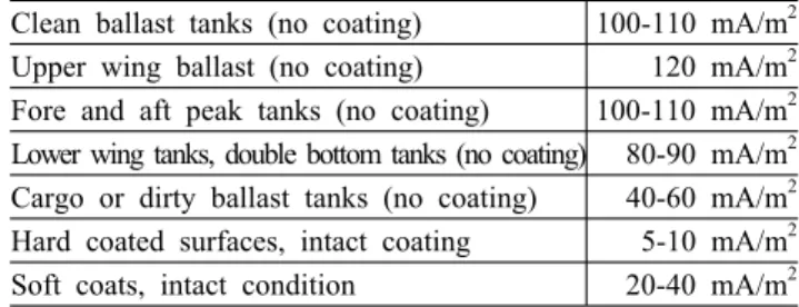
And then, where do they put the coating breaking down factor? They might be incorporated into the design current density value. Referring to average current density demand for the bare steel of ballast water tanks recommended in a guideline published by a ship’s class society as shown in Table 2,11) it could be readily inferred that 5 mA/m2 was obtained considering approximately 5% of coating breakdown with about 100 mA/m2 for clean ballast tanks.
Design life had been determined based upon general dry docking cycle, 5 years, for every full-fledged inspection and repair. On the other hand, it could be noticed that 50% of ballast ratio means inner ballast water tanks will be exposed to seawater immersion condition for only half of the design life.
Second, and then, are the numbers of three CP design parameters in Table 1, really, suitable to water ballast tanks for the corrosion protection? Average current density for bare steel of ballast water tanks in Table 2 is 40-120 mA/m2, which is, not surprisingly, almost consistent with that of marine offshore structures in DNV RP, 60-120 mA/m2. In addition to current density for bare steel, the coating breakdown factor hidden in the design current den
Table 2. Average current density demand to obtain full cathodic protection for ballast water tanks in TSCF guideline Clean ballast tanks (no coating) 100-110 mA/m2 Upper wing ballast (no coating) 120 mA/m2 Fore and aft peak tanks (no coating) 100-110 mA/m2 Lower wing tanks, double bottom tanks (no coating) 80-90 mA/m2 Cargo or dirty ballast tanks (no coating) 40-60 mA/m2 Hard coated surfaces, intact coating 5-10 mA/m2 Soft coats, intact condition 20-40 mA/m2
sity in Table 1 also may be thought as stemming from the design equation for offshore environments originally in DNV RP as shown in equation (9) and Table 3, which is the most well arranged and virtually only one design equation with design life to estimate coating breakdown so far. 5% of coating breakdown (fcm) for the mean or average state shall exactly be obtained by putting ‘a’ and
‘b’ constants for Coating category Ⅲ and design life 5 years into equation (9). However, the plausible argument is the significant difference in the corrosion environment of ballast water tanks and offshore marine structures.
Offshore structures are typically exposed to free air con- tact, sea wave and storm, and more natural marine action, whereas inner ballast tanks of ships are exposed to rela- tively confined quiescent seawater and empty wet con- dition repeatedly. Some type of ships such as cargo oil tankers, in addition to this, may suffer cyclic temperature variation also. These all various factors in ballast water tanks may be affecting in a great different way to the coat- ing integration more or less compared with those of off- shore marine structures. But no systematically organized design protocol has ever been studied or proposed for the coating of ballast water tanks including the factor of design life and ship types so far. There has been only 5 mA/m2 for 5 years life time with 50% ballast ratio, all flat design values. And then, how we may determine the coating breakdown for the 10 or 15 years life time, and do we apply the same design scheme to the coating of ballast water tanks of container carriers, cargo oil tankers or any other ships? Only small increment in design parameters, for example, by 1 mA/m2 or 1 % of coating breakdown from the based on typical design value shall result in 20%
higher CP anode weight for ballast water tanks, thereby, less cargo loading capacity by the same amount. That’s why we have to get focused to making a systematic and reliable design scheme specifically applicable to ballast water tanks of marine ships.
(9)
Table 3. Recommended constants a and b for calculation of paint coating breakdown factors in DNV RP B401 (2005)
Depth, m
Recommended a and b values for coating categories Ⅰ,Ⅱ and Ⅲ
Ⅰ
(a=0.10) Ⅱ
(a=0.05) Ⅲ
(a=0.02)
0-30 b=0.10 b=0.025 b=0.012
>30 b=0.05 b=0.015 b=0.008
Category Ⅰ One layer of epoxy paint coating, min. 20 ㎛ nominal DFT
Category Ⅱ One or more layers of marine paint coating, total nominal DFT min. 250 ㎛
Catetory Ⅲ Two or more layers of marine paint coating, total nominal DFT min. 350 ㎛
Third, are there any over-design factors in this SACP design practice for ballast water tanks? As stated above clause, the conventional design protocol has been consid- ered as producing unnecessary over-design results even for the offshore structures by selecting the largest value among the three design criteria as shown in equation (1), (2) and (3). It was verified by the authors that minimum 33% of anode weight could be removed from the typically arranged design result by an optional substitution design method, or “slop parameter” and “unified design equation”
as being recommended in NACE RP. Moreover, the design parameters such as design current density and the hidden coating breakdown factor are largely put in the design process unnoticeably as an over-design terms also for bal- last tanks, because they basically come from the protocol for offshore facility under more harsh condition. In addi- tion, most long-term experiences as back-up data for de- sign equation (9) are with epoxy-tar coatings, which now have been replaced by new and possibly more improved coating products, and, furthermore, it would be upgraded to much higher quality in a near future by IMO’s PSPC rule. In this regard, Knudsen et al. reported at year 2001 that the coating samples, for example, showed merely 1
% or less coating breakdown for DNV coating category 4 after whole 5 years exposure to seawater, which is sup- posed to suffer 9 % coating breakdown, if based on design equation in DNV RP, thus, the recommended degradation rates for the coatings may be quite conservative, resulting in unnecessary high anode weights.12) Although the Knudsen’s work was done by a laboratory scale, the num- ber reported for coating breakdown is stunningly small compared with that of conventional design base. It is not so much as rare in the actual case to find the sacrificial anode remaining nearly intact even after full 5 years life time too. And another factor to be specifically reviewed in terms of over-design is how ballast ratio should be in-
corporated into design scheme of ballast tanks’ SACP system. In the current practice, ballast ratio has been only introduced into design life time simply by multiplying its factor. However, the factor of ballast ratio should be crit- ically considered into coating breakdown factor or average current density as well, because coating breakdown shall be linearly varied with actual seawater immersion time, not with design life time. For example, typical 5 mA/m2 design current density should be replaced with reduced 3.5 mA/m2 when it comes to the coating of the ballast tanks with 50% ballast ratio for 5 years design life time based on DNV RP equation (8), because in this case actual immersion time comes to total 2.5 years.
Fourth, how could the SACP system design be properly verified by computational analysis? Due to the object size and time-dependent feature, it could be ultimately hard to verify the CP system with life-size or even scale-down model. Therefore, only simulation analysis by computa- tional method has been, generally, accepted as the most effective methodology to reaffirm design results attained by conventional design protocol. To date, only one com- mercial and a couple of house-developed versions of soft- ware, globally, has been limitedly used for offshore ob- jects, which were all originated from BEM (boundary ele- ment method) codes. Regardless of the type of the software used, the critical issue on design task is setting of boundary conditions for analysis, because the accuracy of analysis results are mainly dominated by the data input employed in the form of boundary conditions. The most critical data to be input as boundary conditions are cathode and anode polarization data for seawater immersion condition. In this regard, an European leading expert group for computa- tional analysis, usually, utilizes the two-point data set sim- ply based on design parameters, one point for corrosion potential of cathode steel (for example, -0.6 Volt), and the other point for protective potential (for example, -0.8 Volt) with design current density. The analysis method- ology by this approach may be thought to provide more robust design because all over-design-based data will pro- duce the most conservative results, which often come to require extra additions of CP systems in some cases for the apparently over-designed systems. Thus, it is more rea- sonable to understand that the analysis with more realistic polarization data of such as actual anode material and cath- ode steel in seawater would predict quantitatively the ac- tual life expectancy or design safety factor. Actual current density to attain protective potential of -0.8 volt of steel in seawater is known to be possibly quite lower such as 35 mA/m2 or below compared with 100 mA/m2 of TSCF guideline, which is attributable to protective calcareous de- posit formation on the steel surface in seawater.13) Besides
that, to get more useful verification results, ballast ratio, final coating breakdown factor and anode diminution fac- tor at the end of life time also should be clearly defined and properly introduced in the process of analysis, which have been wholly ignored so far in the current practice.
Especially the factor of ballast ratio should be set into the final life time, final coating breakdown factor and anode diminution factor as well. It is unfortunate that cur- rently only rough approach could be made to estimate anode size diminution with time lapsed in seawater due to the lack of systematic design equation and back-up data.
3.2 Marine ship’s outer hull
For the ICCP system of marine ship’s outer hull, the most part of the design issues dealt with SACP system would be considered by the same token as the previous section. The design process for ICCP system, however, might be thought as comparatively simple, because only a single design equation (6) is needed and then resultant current demand comes to determine the capacity of power suppliers and number of anodes. Contrast to ballast water tanks, design parameters such as current density and coat- ing breakdown factor provided by ship class society are well organized in terms of design year and type of ship.
14) The remaining issues for ICCP system are regarding anode and anode shield in comparison with SACP system, which are reviewed in the followings.
First, how we design the anode material to last as long as ship’ life goes? Generally, ship’s life is expected to be in the range of 20 to 25 years at least, and the same is expected for the anode material of ICCP system.
Although in the application to ICCP system of marine ship’s hull, virtually inconsumable anodes such as Ti/Pt or MMO/Pt are used, from the view of a CP design en- gineer, anyway, these kind of anodes should be designed regarding thickness of Ti or MMO coating to be applied to Pt substrate. They usually utilize design equation (10) with anode consumption rate.
(10)
Here, W: Coating loading, g/m2
C: Max. anode current output, Ampere L: Life of anodes, years
8,766: Conversion factor for time
E: Effective consumption rate of Pt or MMO coat- ing, ㎍/A-hr
106: Conversion factor for weight A: Surface area of anode, m2
Second, how may we optimize distribution of anodes and reference electrodes? In this case, computational anal-
ysis would be a powerful tool to predict their optimum distribution condition. But the critical issues could be on how the coating breakdown may be properly set to ship’s hull, in an uniform way or in a locally concentrated way to ship stern and rudder area which is more realistic situation. To this end, the coating breakdown distribution should be generalized based upon the database of inspec- tional survey for each type of ship with ship’s life time.
Nevertheless, no efforts have been systematically taken so far in the related industry for this purpose. They roughly place the factor of 60-70% to the half of the hull to stern side, and 30-40%, to the opposite half by current design practice.
Third, it is the most critical issue. Are the current in- dustrial criteria for anode shield coating material really appropriate? The dimension of the anode shield and the type of coating material are the two of main issues.
General ship class rule recommend only flat value for the size of anode shield such as 0.8 m or 1.5 m radius from the end of the anode for minimum -1.1 Volt potential crite- rion, regardless of any other CP design condition. On the other hand, British standard only provide the systematic design equation (11) for anode shield size with the factor of anode current output and potential,15) which produce too conservative value, for example, 20 m diameter or larger for 250 ampere anode current with -1.1V minimum potential criterion for cathodic disbondment. Today’s coat- ing quality has been increasingly improved than that at the time of the design equation of British standard firstly issued. If the most systematic design equation for the anode shield size would be practically used, it should be modified by introducing lower minimum potential such as -1.5 Volt or extra modification factor to realize marine ship’s actual situation. In addition to this, the criteria to determine proper anode shield material specified in ship class rule are now too vague to be practical in design process. There are no quantitative or qualitative criteria to decide proper coating material in the current industrial specification. For example, the coating damage amount could be specified after a given standard cathodic disbond- ment test at an accelerated condition for a certain amount of time as a criterion for the anode shield materials.
(11)
Here, r: Radius of shield, meter ρ: Water resisivity, Ω-m I: Max. current output, Ampere Eo: Protective potential, Volt
E: Min. potential for cathodic disbond., Volt
4. Conclusion
Cathodic protection system has been surprisingly ne- glected in terms of corrosion engineering field of marine ship industry, although it has been still, unnoticeably, oc- cupying the most area of marine ships as a back-up an- ti-corrosion measure in combination with the major player or organic coating. In a respect, it is the reason why CP technology has been set aside with low key so far, that the past design protocol, still applied, may provide too tremendous over-design factor to cause any noteworthy technical trouble during the past decades. With time goes on, coating product for marine ship industry has been sig- nificantly improved so far, and, furthermore, the coating application requirement and job control criteria would be more augmented to be able to impart a nearly 15 years useful life to the ballast water tanks, for example, by IMO’s recent strenuous activity on PSPC rule. Thus, the over-design factor for CP system would be getting bigger and bigger unnecessarily, gnawing the interests of all par- ties of marine ship industry, both of ship owners and builders. In this regard, the unified, systematic and reliable new CP system design protocol for marine ships is, seri- ously, required to compromise with current organic coat- ing material and recent international strict regulation for marine ship’s coating.
References
1. S.Evans, Material Performance, 27(2), 9 (1998).
2. J.C. Cochran, Proc. of Offshore Technology Confernece., Paper OTC 3858, Houston, USA, May 5-8 (1980).
3. M.W. Mateer, CORROSION/93, Paper No. 526, Houston, USA (1993).
4. J.H. Kiefer, CORROSION/98, Paper No. 735, Houston, USA (1998).
5. W.H. Hartt, Corrosion, 52(6), pp. 419-427 (1996).
6. W.H. Hartt, Corrosion, 54(4), pp. 317-322 (1998).
7. Recommended Practice, DNV RP B401, Det Norske Veritas (2005).
8. Recommended Practice, NACE RP 0176, NACE International (2003).
9. Recommended Practice, DNV RP B401, Det Norske Veritas (1993).
10. Recommended Practice, NACE RP 0176, NACE International (1994).
11. Guidelines for Ballast Tank Coating Systems, The Tanker Structure Co-operative Forum (2000).
12. O. Knudsen and U. Steinsmo, CORROSION/2001, Paper No. 01512, Houston, USA (2001).
13. S.Chen and W.H. Hartt, Corrosion, 58(1), pp. 38-48 (2002).
14. Recommended Practice, NR- 423- DTO- R00- E, Bureau Veritas (1996).
15. Code of Practice for Land and Marine Applications, BS 7361, British Standard (1991).