Ⅰ. INTRODUCTION
It is difficult to attain satisfactory treatment results in treating fully edentulous patients with conventional complete denture, because it is dependent on variable factors. For example, there are patient’s comprehension, cooporation and the state of residual alveolar ridge.
But, since Branemark’s introduction of osseointegrated implants into the treatment of edentulous patient, one could get better esthetic, functional results. Also, osseointe-grated implants have wide clinical applications such as restoring partially edentulous areas, single tooth replacement, anchorage for orthodontic treatment and maxillofacial defects.
Spiekermann48) said that the treatment modalities of edentulous patients using dental implants could be divided into three groups according to the state of residual alveolar ridge, implant location and number. : removable mucosa- borne overdenture, removable mucosa-borne distal extension prostheses, fixed implant-supported distal extension prostheses.
Previous studies21,22,26,31,33,48,50)have reported that even with certain esthetic problems, fixed prostheses have advantages over the removable mucosa-borne overdentures such as patient satisfaction and their effect on residual alveolar
ridge. However, fixed prostheses using osseointegrated implants require at least 5-10 implants. This imposes financial burden on patients.
Implant-supported overdenture using two implants can be a alternative treatment modality in this situation4,12,15,18,19,23,24,52,53,57). Although the long term results of a large group of patients with overdentures are not yet reported, there have been many reports that implant-supported overdenture is an effective, practical and successful treatment modality10,40). And comparing patient’ s satisfaction regarding function and esthetics, this therapy is comparable to fixed implant prostheses58,56). This therapy requires less time and cost to make the superstructure and less effort to maintain oral hygiene48).
Different attachment systems of the over- denture have been used. A bar-clip attachment is often chosen because of its excellent retention, stability compared to other attach-ment systems and splinting ability with implants14,27,35,46,49,51,53,63).
But, when certain reasons enforce implants to be installed posteriorly or lingually38)and bar-clip attachment system is chosen as retentive attachment, conventional straight bar will be positioned above the floor of the mouth. In such situations, tongue function is severely restricted.
This leads to masticatory, swallowing and
- 대한 치과 보철학회지 Vol. 36 No. 1, 1998 -
A finite element analysis of implant-supported overdenture on the effect of anterior cantilever
Department of Prosthodontics, College of Dentistry, Seoul National University Department of Prosthodontics, Faculty of Dentistry, University Malaya*
Tae-Wook Jung, D.D.S., Young-Soo Kim, D.D.S., M.S.D., PH.D., M.Sc.<O.S.U.>
Chang-Whe Kim, D.D.S., M.S.D., Ph.D., Booi Cie Ling*, D.D.S., B.D.S., M.Sc., FRA.CDs., FADI.
phonetic problems.
Stud attachment, additional implant installation and modification of bar design can be used to solve these problems. But, the use of stud attachment leads to reduction of retentive capability and the additional implant installation raises the treatment fee.
Thus, angular bar which has straight buccal part above the alveolar ridge for attachment of the clip is often used in clinical situations (Fig.1).
But, this angular bar design has unfavorable biomechanical influences. Extra moments are exerted on the implant and surrounding tissue.
These influences play a major role in implant’
s longevity. Nevertheless, angular bar design is often used clinically because of noticeable merits.
The purpose of this study is to investigate the effect of anterior cantilever on implant and surrounding tissue using three dimensional finite element analysis method and to suggest biomechanically agreeable cantilever amount.
Ⅱ. MATERIAL AND METHODS
Various methods are used to analyze the stress in complex structures when they are loaded.
Photoelastic analysis, brittle lacquer coating technique, Moire fringe analysis are some of the
examples. And, among these methods, the finite element analysis is very useful in analyzing stress generated from the external force in a complex structure. The finite element analysis offers some advantages, including accurate representation of complex geometries, easy model fabrication, easycalculation and representation of internal state of stress and other mechanical quantities36). Especially, this method is to be a useful tool in estimating stress around implants of different designs59,60).
When investigating stress around implants in interforaminal regions, there are no discernible differences using three dimensional finite element model of entire mandible or only the interforaminal region35). So, for simplicity of modeling, semianatomic mandibular bone block which simulated only interforaminal region was used.
Standard Branemark dental implant system (Nobel Biocare AB, Gothenburg, Sweden) was installed in the first premolar area. To evaluate the effects of implant’s length on stress distribution, implant length had two variants, 13 and 15mm.
The size and physical properties of abutment cylinder, abutment screw, gold cylinder, gold screw were identical those used in actual clinical situations.
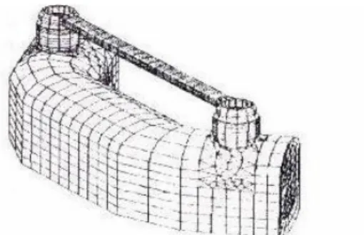
When two implants were used for support under an overdenture, it was best to place them medial to the canine region with approxi-mately 22-27mm distance between the centers of the implants. At this distance, there were the least amount of torque on the implants17). Thus, the length of the straight buccal part was assumed to be 20mm. The bar was assumed to be made out of ADA type IV gold and 2mm in diameter. The bar connecting the implants had six anterior cantilever lengths from 0mm to 5mm (Fig. 2).
The magnitude and the direction of relevant Fig. 1. Models of bar design.
bite force were derived from the studies of Haraldson et al16) and Koolstra et al29). A horizontal(0�=parallel with the occlusal plane) bite force(Fh=10N), a vertical(90�) bite force (Fv=35N) and an oblique(120�) bite force(F�
=70N) were selected. The loading force on the model was static. One node on the midline of the straight bar was loaded(Fig. 3).
All materials were regarded as isotropic, homogeneous and lineally elastic. Properties of each material are shown at Table 1(1,35,36). A fixed bond was assumed between bone and implant along the whole interface. This means that under any loading, no relative motion occurs between bone and implants. Restraint was estabilished at the distal part of the model, which allowed bending movement of the mandible on loading.
Model was composed of 14712 node and 7703 element. To investigate stress distribution pattern around implants in detail, detailed mesh generation was made near implants.
I-DEAS software(Master series version 2.1, Structural Dynamic Research Corp., Milford, Ohio, U.S.A.) package was used for the construction of the models and Anysis Revision 5.0 (Swanson Analysis System Corp., U.S.A.) was the software for analysis. All softwares were mounted on Iris-work station (Silicongraphics Corp., U.S.A.)
Ⅲ. RESULTS
Through the process of finite element analysis, the amount of stress and displacement which correspond to each node and element were calculated. But, for comparison of the models, analyzing all the calculated data was unnecessary and time-consuming. So, because tensile force2,43,46,61,62)is the main force that destory osseointegration, maximal principal stress representing tensile force was selected for Fig. 2. Semianatomic mandibular bone block with
implant and bar. Fig. 3. Loading condition.
Table 1. Material properties
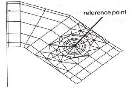
comparing the calculated data of eachmodel. The center of the gold screw was chosen for reference point to investigate theamount of the displacement (Fig. 4). The cross sectional view of 13mm implant and surrounding bone when loaded obliquely was selected to evaluate stress distribution patterns around implant and surrounding bone.
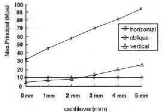
1) Maximal principal stress and displacement of 13mm implant.
In case of vertical force, there was the least
amount of stress concentration and displacement with 0mm cantilever. Increasing cantilever caused stress to increase slowly initially. But, beyond 2- 3mm, the rate of increase became steeper and at 4mm cantilever, concentrated stress became greater than horizontal force. Horizontal force had insignificant effect on stress concentration.
Oblique force, from the first stage, had high stress levels and steep inclination. The change in displacement was similar to stress concentration.
Except for horizontal force, all increased in proportional to the length of cantilever (Fig. 5,6).
Fig. 4. Reference point for displacement.
Fig. 5. Maximal principal stress of 13mm implant. Fig. 6. Displacement of 13mm implant.
2) Maximal principal stress and displacement of 15mm implant.
The results were almost the same as 13mm implant, except that the threshold at which the inclination changed abruptly was 2mm. The change pattern of the displacement was almost the same (Fig.7, 8).
3) The effect of horizontal force on stress distribution and displacement.
The effect of horizontal force on maximal principal stress was insignificant. Increasing implant length was effective in reducing concentrated stress. Surprisingly, the longer
cantilever showed less displacement to the horizontal loading than shorter (Fig. 9, 10).
4) The effect of oblique force on stress distribution and displacement.
Increasing cantilever was directly proportional to stress concentration. Implant length had no effect on reducing stress. The change pattern of the displacement was similar (Fig. 11, 12).
5) The effect of vertical force on stress distribution and displacement.
Initially, the amount of maximal principal stress in both implants increased slowly as the
Fig. 7. Maximal principal stress of 15mm implant. Fig. 8. Displacement of 15mm implant.
Fig. 9. Maximal principal stress of horizontal loading. Fig.10. Displacement of horizontal loading.
amount of cantilever increased. And, after the amount of cantilever was bigger than 2-3mm, the rate of increase became steeper. although the longer implant was effective at first in reducing stress, there were no difference between long and short beyond 3mm. The amount of displacement was directly proportional to cantilever length regardless of implant length(Fig.13,14).
6) The stress distribution pattern
At 0mm cantilever, stress was widely dispersed through symphysis and surrounding cancellous bone and concentrated in the joint area which connects the bar and the implants.
Increasing cantilever reduced stress dispersion
through symphysis, surrounding bone and concentrated stress on certain cortical bone and internal surface of the implant.
Ⅳ. Discussion
The biomechanical aspects play a major role in the longevity of implants34,41,47). Masticatory force is passed through the implant to surrounding bone.
If the force was con-centrated in a certain area, the destructive remodeling process of bone would happen and finally implant would fail(3,30,42). The most favorable force for implant is vertical force along the axis of implant and shear, tensile force Fig.11. Maximal principal stress of oblique loading. Fig.12. Displacement of oblique loading.
Fig.13. Maximal principal stress of vertical loading. Fig.14. Displacement of vertical loading.
which cause bending moment elicits unfavorable effect at implant-bone interface2,43,53,61,62). Therefore, when designing implant prostheses, minimizing bending moment should be major consideration. To do this, the position and number of implant become important factors2,37,43).
Because implant-supported overdenture mainly take support from residual alveolar ridge like conventional complete denture, designing superstructure which could distribute stress evenly into implant and surrounding tissue is very important13,17,32,34,45).
To satisfy this biomechanical requirement, the attachment connecting the implant and superstructure should be selected carefully. Many attachment systems have been used with its specific merits and demerits9,10,15,44). Thus, attachment selection should be individualized according to the characteristics of each system and patient’s condition. English9,10) devised the following selection criteria : versatility, maintenance, vertical space, cost, bio-mechanical function, ease of replacement.
The attachments in wide use could be divided into two groups. : Bar-clip attachments and single attachments that composed of stud and magnet.
Single attachments have advantage in stress distribution, clinical application and oral hygiene maintenance5,6,20,45,54). Meanwhile, bar-clip attachments have excellent retention and stability compared to single attachments in addition to its splinting effect14,27,35,46,49,51,53,63).
Because edentulous patients who seek implant prostheses mainly complain of the loss of retention and stability, bar-clip attachment which has superior retention and stability is widely used
14,27,35,46,51,53). However, increased stability and retention is necessarily accom-panied by the increase of stress on implants51,55). Thus, to
minimize bending moment and to distribute stress evenly into implant and residual ridge, designing of straight bar which allows rotational movement of superstructure is essential and the rotational axis should be parallel to interhinge axis7,8,25,48,63). This can be easily accomplished when implants are installed in the canine area.
But, when anatomic limitations enforce implants to be installed posterioly or lingually and bar-clip attachment is chosen as retentive element, conventional straight bar will be posi-tioned above the floor of the mouth. In such situations, tongue function is severely restricted. This leads to masticatory, swallowing, phonetic problems10,36,41). Such situation occurs when alveolar ridge is narrow. In this case, as installing implants too close together cause loss of retention17), implants should be installed posteriorly for suitable retention. This is also applicable in lingually inclined alveolar ridge due to severe resorption.
Additional implant installation, the use of stud attachment, modification of bar design which has straight buccal part above alveolar ridge36)can be solutions of the above problems. Among these solutions, modification of bar design, called angular bar, imposes great bending moment in the implant. However, angular bars have been used often because stud attachment has lower retentive ability and additional implant installation requires higher fees.
In a study which compared angular bar design with 6mm anterior cantilever, stud attachment and additional implant installation using three dimensional finite element analysis, angular bar design showed the greatest stress concentration.
Thus the use of stud attachment or additional implant installation were recommended for the longevity of the implant in posterioly installed situations36).
In another study of anterior cantilever design, there are three risk factors in this design : 1. Dead space which results from labial/lingual extension of superstructure for covering retentive clip cause bacterial colonization. 2. Difficulty of biomechanical loading. 3. Mucosal irritation. So, the use of angled or second stage coping which can reduce bulky lingual structure was recommended39).
In this study, the effect of angular bar design which had 6 cantilever length from 0mm to 5mm on implant and surrounding tissue was investigated using three dimensional finite element analysis. In addition, implant length had two variants, 13 and 15mm to study the effect of implant length.
Fig 5,6,7,8 showed the amount of maximal principal stress, displacement when oblique, horizontal, vertical force was loaded on 13,15mm implant. The two group had similar change patterns. Because the direction of horizontal force was parallel to the direction of cantilever extension, there was no significant change. At 0mm cantilever, under vertical load, the amounts of tensile force and displacement were minimal.
But, as cantilever length increased, vertical loading showed specific change pattern. Initially, the amount of maximal principal stress in both implants increased slowly as the amount of cantilever increased. Then, after the amount of cantilever was bigger than 2-3mm, the rate of increase became more dramatic. From this result, it could be concluded that anterior cantilever didn’
t cause unfavorable bending moment within the limit of implant diameter. But, beyond the limit, even vertical force caused harmful bending moment. Oblique force caused the largest stress concentration, displacement from the first and maintained a steep inclination. This result
coincided with the conclusion of previous studies that oblique force caused the most harmful effect on implants and surrounding tissue.
Fig 9,10 showed the effect of horizontal force on stress distribution and displacement. Because the direction of horizontal force was parallel to the extension of anterior cantilever, as mentioned previously, there were no significant changes.
Rather, increasing cantilever caused the amount of displacement to reduce a little. The cantilever bar structure had the extension component which connects implant and anterior straight bar. Because this part had the potential to resist to horizontal force, the longer cantilever showed less displacement. The longer implant showed lesser stress concentration and displacement than the shorter because increased bone-implant interface to loading direction had distributed stress more widely into surrounding tissue.
Fig 11,12 showed the effects of oblique force on stress distribution and displacement. As the length of cantilever increased, the effect of oblique force became more dramatic and the length of the implant had no effect on maximal principal stress and the amount of displacement. In oblique loading, loading direction seemed not to distribute stress through bone-implant interface but to concentrate stress on certain cortical bone areas.
Fig 13,14 showed the effect of vertical force on stress distribution and displacement. Initially, the amount of maximal principal stress in both implants increased slowly as the amount of cantilever increased. And, after the amount of cantilever was bigger than 2-3mm, the rate of increase became more dramatic. Before reaching the threshold, the larger implant showed lesser stress. But once the threshold had been reached, there was no discernible difference according to the length. As mentioned earlier, loading within
the limit of the implant diameter doesn’t exert significant bending moment so that stress is distributed widely through the bone-implant interface. But, loading beyond the limit, like the effect of oblique force, causes stress concentration on certain cortical bone rather than stress distribution.
At 0mm cantilever, much more stress were dispersed through surrounding cancellous bone and symphysis area and only a little stress were concentrated on the joint area which connects the bar and the gold cylinder. As cantilever length increased, stress distribution pattern showed lesser dispersion through surrounding bone and symphysis area. And stress concentration was observed on certain areas of cortical bone, implant and the overlying prosthesis. This stress distribution pattern is due to the fact that the greater bending moment results from the longer cantilever causing stress to be concentrated rather than dispersed and the longer elastic bar results from the longer cantilever causing more stress to be absorbed into the overlying prosthesis and implant.
According to previous studies and the above results, angular bar design not only concentrates stress on surrounding cortical bone, superstructure and implant, but also reduce stress dispersion through bone. So, the possibility of bone resorption and bar fracture might be increased.
From the point of view that this treatment modality is dependent on stress distribution, angular bar is not a suitable design. But in unavoidable situations, implant length should be as long as possible and anterior cantilever length should be less than 3mm not to be longer than implant diameter.
Ⅴ. Conclusions
To study anterior cantilever effect on implant and surrounding tissue, we designed and pro- cessed three dimensional finite model and could get following conclusions.
The conclusions were as follows :
1. As the length of the cantilever increased, stress was concentrated on the implant and surrounding bone and the amount of dis- placement was increased.
2. The effect of horizontal force was not significant. The longer 15mm implant showed lesser stress and displacement.
3. As the length of the cantilever increased, the effect of oblique force on the amount of the stress became more dramatic. The length of the implant had no effect on maximal principal stress and the amount of displacement.
4. Initially, vertical force showed only mild influence on stress. But, after a certain point, the effect became more dramatic. Before reaching the threshold, longer implants showed lesser stress. But once the threshold had been reached, there was no discernible difference according to the length.
5. Stress distribution pattern showed, with increasing length of cantilever, lesser dispersion through bone with stress being concentrated on certain areas of cortical bone, implants and the overlying prosthesis.
6. From the point of view that this treatment modality is dependent on stress distribution, angular bar was not a suitable design. But in unavoidable situation, implant length should be long as possible and the length of cantilever should be less than 3mm.
Reference
1. Bidez MW, Chen Y, McLoughlin SW, English CE : Finite element analysis(FEA) studies in 2.5-mm round bar design : The effects of bar length and material composition on bar failure. J Oral Implantol 1992 ; 18 ; 122-8.
2. Bidez MW, Misch CE : Force transfer in implant dentistry : Basic concepts and prin- ciples. J Oral Implantol 1992 ; 18 ; 264-73.
3. Borchers L, Reichart P : Three dimensional stress distribution around a dental implant at different stages of interface development. J Den Res 1983 ; 62 ; 155-9.
4. Cune MS, de Putter C, Hoogstraten J : A nationalwide evaluation study on implant- retained overdentures. J Dent 1997 ; 25 ; S13-S19.
5. Davis DM : The ERA implant-supported overdenture. Compendium 1995 ; 16 ; 512 - 20.
6. Davis DM : Implant supported overdentures - the King’s experience. J Dent 1997 ; 25 ; S33- S37.
7. Dickerman IN : Preferred designs of mandibular implant overdentures. Dent Implant Update 1997
; 4 ; 29-32.
8. Dolder EJ, Durrer GT : The bar-joint den-ture : A practical textbook. Quintessence Publishing Co., Inc 1978. p13-25.
9. English CE : Prosthodontic prescriptions for mandibular implant overdentures - part I. Dent Implant Update 1996 ; 7 ; 25-8.
10. English CE : Prosthodontic prescriptions for mandibular implant overdentures - part II. Dent Implant Update 1996 ; 7 ; 38-40.
11. Engquist B : Six year experience of splinted and nonsplinted implants supporting overdenture in upper and lower jaw. In : Overdentures on Oral implants. Proceeding of symposium on implant- supported over-denture by the European
Osseointegrated Training Center, 1989, Brussels.
12. Geertman ME, Slagter AP, van WaasMAJ, Kalk W : Comminution of food with man- dibular implant retained overdentures. J Dent Res 1994 ; 73 ; 1858-64.
13. Humphris GM, Healey T, Howell RA, Cawood J : The psychological impact of implant-retained mandibular prostheses : A cross - sectional study.
Int J Oral Maxillofac Implants 1995 ; 10 ; 437-43.
14. Glantz Per-Olof, Nilner K : Biomechnical aspects on overdenture treatment. J Dent 1997 ; 25 ; S21-S24.
15. Gotfredsen K : Implant supported over-dentures - the Copenhagen experience. J Dent 1997 ; 25 ; S39-S42.
16. Haraldson T, Carlsson GE : Bite force and oral function in patients with osseointe- grated oral implants. Scand J Dent Res 1997 ; 85 ; 200-8.
17. Hertel RC, Kalk W : Influence of the dimensions of implant superstructure on peri-implant bone loss. Int J Prosthodont 1993 ; 6 ; 18-24.
18. de Hernandez CJ, Bodine RL : Mastication strength with implant dentures as compared with soft tissue-borne dentures. J Prosthet Dent 1969
; 22 ; 479-86.
19. Hooghe M, Naert IE : Implant supported overdentures - the Leuven experience. J Dent 1997 ; 25 ; S25-S32.
20. Ichikawa T, Horiuchi M, Wigianto R, Matsumoto N : In vitro study of mandibular implant- retained overdentures : The influe-nce of stud attachments on load transfer to the implant and soft tissue. Int J Prosthet 1996 ; 9 ; 394-9.
21. Jacobs R : Maxillary bone resorption in patients with mandibular implant-supported overdentures or fixed prostheses. J Prosthet Dent 1993 ; 70 ; 135-40.
22. Jacobs R, Schotte A, van Steenberghe D, Quirynen M, Naert IE : Posterior jaw bone
resorption in osseointegrated implant- supported overdentures. Clin Oral Impl Res 1992 ; 3 ; 63- 70.
23. Jacobs R, van Steenberghe D, Naert I : Masseter muscle fatigue before and after rehabilitation with implant-supported pro-sthesis. J Prosthet Dent ; 1995 ; 73 ; 284-9.
24. Jemt T, Lindquist L, Hedegard B : Changes in chewing patterns of patients with complete dentures after placement of osseointegrated implants in the mandible. J Prosthet Dent 1985 ; 53 ; 578-83.
25. Jemt T, Carlsson L, Boss A, Jorneus L : In vivo load measurements on osseointegrated implants supporting fixed or removable prostheses : A comparative pilot study. Int J Oral Maxillofac Implants 1991 ; 6 ; 413-7.
26. Jemt T, Book K : Failures and complications in 92 consecutively inserted overden tures supported by Branemark implants in severely resorbed edentulous maxillae : A study from prosthetic treatment to first annual check-up.Int J Oral Maxillofac Implants 1992 ; 7 ; 162-7.
27. Jemt T, Book K, Karlsson S : Occlusal force and mandibular movements in patients with removable overdentures and fixed prostheses supported by implants in the maxilla. Int J Oral Maxillofac Implants 1993 ; 8 ; 301-8.
28. Jemt T, Chai J, Harnett J,Heath MR, Hutton JE : A 5-year prospective multi-center follow-up report on overdentures supported by osseointegrated implants.Int J Oral Maxillofac Implants 1996 ; 11 ; 291-8.
29. Koolstra JH, Weijs WA, Naeije M : A three- dimensional mathematical model of the human masticatory system predicting maximum possible bite forces. J Biomech 1988 ; 21 ; 563-76.
30. Lavernia CJ : The effect of implant elastic modulus on the stress distribution surrounding
dental implants. In : International Conference Proceeding, Finite Elements in Biomechanics (DE. B.R. Simon) p19.
31. Lindquist LW, Rockler B, Carlsson GE : Bone resorption around fixtures in edentulous patients treated with mandibular fixed tissue-integrated prostheses. J Prosthet Dent 1988 ; 59 ; 59-63.
32. Lipkin JN, Hoffer M : The implants supported mandibular bar overdenture : Diagnosis and treatment planning. J Can Dent Assoc 1994 ; 60 ; 779-84.
33. Maxson BB : Prosthodontic considerations for the transmandibular implant. J Prosthet Dent 1990 ; 63 ; 554-8.
34. Meijer HJA, Kuiper JH, Starmans FJM, Bosman F : Stress distribution around dental implants : Influence of superstructure, length of implants, and height of mandible. J Prosthet Dent 1992 ; 68
; 96-102.
35. Meijer HJA, Starmans FJM, Steen WHA, Bosman F : A comparison of three finite element models of an edentulous mandible provided with implants. J Oral Rehabil 1992 ; 20 ; 147-57.
36. Meijer HJA, Starmans FJM, Steen WHA, Bosman F : Location of implants in the interforaminal regions of the mandible and the consequences for the designs of the superstructure. J Oral Rehabil 1994 ; 21 ; 47-56.
37. Meriscke-Stern R, Geering AH, Burgin WB, Graf H : Three dimensional force measurement on mandibular implants supporting overdentures.
Int J Oral Maxillofac Implants 1992 ; 7 ; 185-94.
38. Meriscke - Stern R : Forces on implants supporting overdentures : A preliminary study of morphologic and cephalometric considerations.
Int J Oral Maxillofac Implants. 1993 ; 8 ; 254-63.
39. Manning KE, Razzoog ME : The use of an anterior cantilever design for an implant retained overdenture : A case report. J Can Dent Asso
1990 ; 56 ; 1105-7.
40. Naert IE, Quirijnen M, Theuniers G, Van Steenberghe D : Prosthetic aspects of osseointegrated fixtures supporting over- dentures. A 4-year report. J Prosthet Dent1991 ; 65 ; 671.
41. Naert IE : Patient evaluation and treatment planning. J Dent 1997 ; 25 ; S5-S11.
42. Pugh JW, Rose RM, Radin RL : Elastic and viscoelastic properties of trabecular : dependence on structure. J Biomechanics 1973 ; 6 ; 475.
43. Rangert B, Jemt T, Jorneus L : Force and moments on Branemark implants. Int J Oral Maxillofac Implants 1989 ; 4 ; 241-7.
44. Renner A : The implant overdenture and designated attachments - the mandible. Dent Implant Update 1996 ; 7 ; 18-21.
45. Rigdon TF : The removable implant over-denture -”Why didn’t someone tell me that?”. J Oral Implantol 1996 ; 12 ; 59-62.
46. Setz J, Kramer A, Benzing U, Weber H : Complete denture fixed on dental implants : chewing patterns and implant stress. Int J Oral Maxillofac Implants 1989 ; 4 ; 107-11.
47. Skalak R : Biomechanical considerations in osseointegrated prostheses. J Prosthe Dent 1983 ; 49 ; 843-8.
48. Spiekermann H, Donath K, Hassell T, Jovanovic S, Richter J : Implantology. Color Atlas of Dental Medicine. New York, Thieme Medical Publishers, Inc., 1995, p146-208.
49. Stumpel LJ : Implant bar design, the next generation. J Can Dent Assoc 1996 ; 24 ; 37-44.
50. Sybille KL : Combination syndrome in relation to osseointegrated implant-supported overdenture : A survey. Int J Prosthodont 1996 ; 9 ; 58-64.
51. Thayer HH, Caputo AA : Photoelastic stress analysis of overdenture treatment. J Prosthet Dent 1980 ; 43 ; 611-7.
52. Benzing U, Weber H, Simonis A, Engel E : Changes in chewing pattern after implant- ation in the edentulous mandible. Int J Oral Maxillofac Implants 1994 ; 9 ; 207-13.
53. Walmsley AD, Nilner K : Overdentures- when and how. J Dent 1997 ; 25 ; S1-S3.
54. Walmsley AD, Frame JW : Implant supported overdentures - the Birmingham experience. J Dent 1997 ; 25 ; S43-S47.
55. Warren AB, Caputo AA : Load transfer to alveolar bone as influenced by abutment designs for tooth-supported dentures. J Prosthet Dent 1975 ; 33 ; 137-47.
56. Walton : Problem with prosthesis on implants : A retrospective study. J Prosthet Dent 1994 ; 71 ; 283-8.
57. Von Wowern : ITI implants with over-dentures : A prevention of bone loss in edentulous mandibles?. Int J Oral Maxillofac Implants 1990 ; 5 ; 135-9.
58. Zarb GA : The edentulous predicament 2 : The longitudinal effectiveness of implant -supported overdentures. J Ame Dent Asso 1996 ; 127 ; 66-72.
59. Kwon HB, Kim CW, Kim YS : A three- dimensional finite element analysis of osseointegrated implant on stress distribution in different abutment designs and fixture diameters. J of Korean Academy of Prosthodontics 1996 ; 34 ; 699.
60. Kim DW, KimYS : A Study on the osseointegrated prosthesis using three dimension-al finite element method. J of Korean Academy of Prosthodontics 1991 ; 291) ; 167.
61. Kim YH, Kim CW, Kim YS : A three dimensional finite element analysis study of elastic deformation of mandible with osseointegrated implant prostheses. J of Korean Academy of Prosthodontics. 1997 : (in processing)
Explanation of figures
Fig. 1. Bar design : 0mm cantilever.
Fig. 2. Bar design : 5mm cantilever.
Fig. 3. Stress distribution of bone at 0mm cantilever. (frontal section view) Fig. 4. Stress distribution of bone at 0mm cantilever. (horizontal view) Fig. 5. Stress distribution of implant at 0mm cantilever. (frontal section view) Fig. 6. Stress distribution of bone at 1mm cantilever. (frontal section view) Fig. 7. Stress distribution of bone at 1mm cantilever. (horizontal view) Fig. 8. Stress distribution of implant at 1mm cantilever. (frontal section view) Fig. 9. Stress distribution of bone at 2mm cantilever. (frontal section view) Fig. 10. Stress distribution of bone at 2mm cantilever. (horizontal view) Fig. 11. Stress distribution of implant at 2mm cantilever. (frontal section view) Fig. 12. Stress distribution of bone at 3mm cantilever. (frontal section view) Fig. 13. Stress distribution of bone at 3mm cantilever. (horizontal view) Fig. 14. Stress distribution of implant at 3mm cantilever. (frontal section view) Fig. 15. Stress distribution of bone at 4mm cantilever. (frontal section view) Fig. 16. Stress distribution of bone at 4mm cantilever. (horizontal view) Fig. 17. Stress distribution of implant at 4mm cantilever. (frontal section view) Fig. 18. Stress distribution of bone at 5mm cantilever. (frontal section view) Fig. 19. Stress distribution of bone at 5mm cantilever. (horizontal view) Fig. 20. Stress distribution of implant at 5mm cantilever. (frontal section view)
=국문초록=
임플랜트 bar overdenture에서 bar 의 cantilever양이 임플랜트에 미치는 영향에 관한 삼차원 유한요소분석적 연구
정태욱∙김영수∙김창회∙Booi Cie Ling
서울대학교 치과대학 보철학교실
두개의 임플랜트로 지지되는 overdenture를 이용한 하악무치악환자의 치료법은 경제적이면서, 실용적인 치료로 인정을 받고 있다. 하지만 해부학적인 조건으로 임플랜트를 설측 혹은 후방에 식립해야 되는 경우에는 일반적인 bar설계는 bar가 구강저 상방을 지나게 되어 혀운동, 발음, 위생관리등에 많은 문제점을 부여한다. 이에 대한 해결 방법으로 전방부 치조제 상에 보철물의 회전을 허용하는 angular bar를 설계할 수 있다. 하지만 이 설계는 임플랜 트에 불리한 moment를 유발한다. 그럼에도 불구하고 뛰어난 유지력과 지지능력, 경제적인 면 때문에 angular bar는 임상에서 많이 사용되고 있다. 이에 본 연구는 angular bar의 전방 cantilever양을 달리하여 임플랜트 및 주 변조직에 미치는 영향을 삼차원 유한요소분석법을 통해서 알아보고자 하였다.
이공사이의 하악골을 단순화시킨 준하악골모형에 직경 3.75mm인 브로네마르크 임플랜트 2개를 길이가 13,15mm인 경우로 설정하여 제 1소구치 부위에 식립하였다. 두 임플랜트를 연결하는 bar는 전방부 cantilever양 을 0-5mm, 1mm씩 하여 6가지 경우를 가정하고 제작하였다. 각각 bar 중앙부에 수직압 (90도) 35N, 경사압(120 도) 70N, 수평압(0도) 10N을 가하였으며 이때 나타나는 응력분산형태와 임플랜트의 골유착에 불리하게 작용하는 최대주응력(인장력)과 변위량을 살펴보았다. 연구결과 다음과 같은 결론을 얻었다.
1. Cantilever양이 증가할수록 주변피질골과 임플랜트로 응력이 집중되었으며 상부 보철물의 변위량도 커졌다.
2. Cantilever양에 대한 수평압의 영향은 크지 않았으며 임플랜트 길이가 긴 것이 변위량과 응력이 작았다.
3. 경사압에 대한 응력의 변화는 cantilever양의 증가에 따라 급격히 증가하는 양상을 띠었으며 임플랜트길이가 응력 및 변위의 양에 미치는 영향은 없었다.
4. 수직압에 대한 응력의 변화는 초기에는 완만한 증가를 보이다가 일정 시점 지난 후에는 증가율이 커지는 경향을 띠었다. 증가현상이 두드러지기 전에는 길이의 증가가 응력의 분산효과는 가져왔으나 이후에는 길이의 응력분 산효과는 없었다.
5. 응력분포양상은 cantilever양이 증가할수록 골조직을 통한 분산정도는 작아지고 특정부위의 피질골과 임플랜 트, 상부보철물에 집중되는 경향을 보였다.
6. 임플랜트와 주변 골조직으로의 응력분산능력이 예후를 좌우한다는 점에서 angular bar는 적합치 못하며 부득 이한 경우는 임플랜트 길이를 길게 하고 최대한 3mm이내로 cantilever양을 제한하는 것이 추천된다.
주요어 : bar - supported overdenture, angular bar, cantilever, 삼차원 유한요소법, 응력, 분산