pISSN 1229-3008 eISSN 2287-6251
Progress in Superconductivity and Cryogenics
Vol.17, No.3, (2015), pp.23~27 http://dx.doi.org/10.9714/psac.2015.17.3.023
```
1. INTRODUCTION
Quadruple magnets are widely used in accelerator for focusing the transporting beams of particles [1, 2] and the field uniformity in good field region reflects the quality of the quadruple magnet. However the requirements for the field quality in the good field region of quadruple magnet can be different between applications. This study is related with the HTS quadruple magnet of RAON system from RISP(Rare Isotope Science Project) in Korea.
In order to provide the desired field configuration in quadruple magnet, appropriate position of the coils and the shape of the iron pole should be decided with high accuracy.
To improve the field quality, A. Kalimov et al optimized the pole shape of quadruple magnets to remove the high-order harmonics with some preconditions [3, 4]. On the contrary, the characteristics of the magnetic field from HTS quadruple magnet was illustrated to explain the cause of inhomogeneity of quadruple magnet through this study.
Based on the HTS quadruple magnet of RAON system, the total magnetic field B was separated into the coil-induced magnetic field B s and the iron-induced magnetic field B c to explain why the total magnetic field B has some inhomogeneity. Using Fourier analysis, the harmonic components of B s , B c and B were analyzed in the good field region, respectively. In order to obtain B s and B c , the iron core model and air core model were established.
The harmonic components of B s were obtained in the air core model. The harmonic components of B were obtained
in the iron core model. Then, the harmonic components of B c can be obtained from harmonic components of B s and B.
2. THEORY
To describe the magnetic field distribution in good field region of quadruple magnet, it is convenient to express the magnetic field in terms of harmonics. The radial and the azimuthal components of magnetic flux density in polar coordinate system can be expressed as follows [5]
(1)
where ρ is radius and φ is azimuthal angle in polar coordinate system, n is integer greater than zero, K n are constants and B ρ and B φ are the radial and the azimuthal components of magnetic flux density, respectively.
If we define the amplitudes of n th magnetic field component as B ρn and B φn , they can be expressed by
(2)
B ρn and B φn are constants if the radius ρ is fixed and must be same theoretically. Considering B ρ and B φ are periodic functions, Fourier analysis can be used to calculate B ρn and B φn like (3).
Magnetic field characteristics from HTS quadruple magnet of in-flight separator for a heavy ion accelerator
Zhan Zhang a , Sangjin Lee *,a , Hyun Chul Jo b , Do Gyun Kim b , and Jongwon Kim b
a Uiduk University, Gyeongju, Korea
b Rare Isotope Science Project, Institute for Basic Science, Korea
(Received 10 August 2015; revised or reviewed 22 September 2015; accepted 23 September 2015)
Abstract
Quadruple magnet is an essential component for the accelerator, and the field uniformity in the good field region reflects the quality of quadruple magnet. In this paper, the total magnetic field B was separated into the coil-induced magnetic field B s and the iron-induced magnetic field B c to explain why the total magnetic field B has some inhomogeneity. Using Fourier analysis, harmonic components of B s , B c and B have been analyzed at good field region, respectively. The harmonics of multipole magnet and Fourier analysis are helpful to show the uniformity of magnetic field. Several geometries of yoke and coils were defined to analyze the effect on field uniformity of an HTS quadruple magnet. By the analysis, it was found that the sixth harmonics which is the main factor of field inhomogeneity can be reduced to zero. It means that the sixth harmonics of the magnetic field B can be removed by adjusting the geometry of the magnet pole and the position of coils. We expect that this result can effectively improve the uniformity of an HTS quadruple magnet.
Keywords: field uniformity, Fourier analysis, heavy ion accelerator, HTS quadruple magnet
* Corresponding author: [email protected]
( ) ( )
( ) ∑ ( )
∑
∞
=
−
∞
=
−
=
=
1 1 1
1
cos ,
sin ,
n n n n
n n
n K
B
n K B
ϕ ρ ϕ
ρ
ϕ ρ ϕ
ρ
ϕ ρ
1
=
n n−n
K
B
ρρ
1
=
n n−n
K
B
ϕρ
Magnetic Field Characteristics from HTS Quadruple Magnet of In-Flight Separator for a Heavy Ion Accelerator
Fig. 1. Magnetic field distribution and equipotential lines for an ideal quadruple magnet.
(3) For ideal quadruple magnet, there is only second component i.e. 2φ component and other components are zero. Thus, we can get the magnetic flux density
2 2 2 2
ρ ϕ
ρ
ρ
ϕ
ρ B B K B
B ( , ) = + = = , therefore the magnetic field for ideal quadruple magnet must be proportional to ρ and constant everywhere for fixed ρ. Fig. 1 shows the magnetic field distribution and the equipotential lines for an ideal quadruple magnet. Because of symmetry, the magnetic flux density at point P 1 and point P 2 should be equal.
However some of other harmonic components inevitably exist for practical magnet. To explain the magnetic field characteristics for quadruple magnet, we analyzed only radial component because the amplitude of radial components B ρn and the amplitude of azimuthal components B φn are same. By symmetry, the magnetic flux density can be expressed as follows
(4) Using this symmetry, magnetic flux density can be expressed more recognizably like (5)
(5)
Therefore the magnetic field in a practical quadruple magnet has the values when n=2, 6, 10… and so on. 2φ component is the main value for magnetic field and 6φ or higher order components make inhomogeneity. Generally, we can define field uniformity U for quadruple magnet as follows, because 6φ component is the main factor of field inhomogeneity. All the harmonic components were calculated for ρ=R ref through this paper, where R ref is the reference radius for good field region.
(6)
Considering the longitudinal direction i.e. z axis, the field uniformity can be expressed even though the equation for B ρ is different from (1) or (3 ) t o express the field uniformity in the focusing area
(7)
The field gradient G which shows the actual maximum operating magnetic flux density of quadruple magnet at reference radius of good field region is defined as
(8)
Finally, the effective length L eff [6] which means the actual length of focusing area is expressed by
(9)
3. ANALYSIS 3.1. HTS Quadruple Magnet
HTS quadruple magnet is composed of an iron yoke and coils. The iron yoke is defined in Fig. 2(a), and the corresponding parameters are shown in Table I. The pole surface has hyperbolic section which is cut by a cutting line with cutting angle α. The coil was defined in Fig. 2(b), and the corresponding parameters are shown in Table II. The coil was constructed with 4 DPC HTS coils.
(a) Parameters of iron yoke. (b) Parameters of coil.
Fig. 2. Parameters for HTS quadruple magnet.
TABLE I P ARAMETERS OF IRON YOKE .
Item Symbol Value
Inner radius of yoke (mm) R
yi290
Outer radius of yoke (mm) R
yo520
Yoke length (mm) L
y480
Pole tip radius (mm) R
pt168
Reference radius of good field region (mm) R
ref150
Angle of cutting pole (
o) a 20
( )
−
= ρ π ϕ
ϕ
ρ
ρρ
, B , 2
B
( ) ( ) ( )
( ) 10 sin ( ) 14 ...
sin
6 sin 2
sin ,
14 10
6 2
+ +
+
+
=
ϕ ϕ
ϕ ϕ
ϕ ρ
ρ ρ
ρ ρ
ρ
B B
B B
B
% 100
2 6
×
=
ρ ρ
B U B
R
refG = B
ρ2( ) ( ) ϕ ϕ π
ϕ π ϕ
π ϕ ϕ
π ρ ρ
d n B B
d n B B
n n
∫
∫
=
=
2 0 2 0
1 cos 1 sin
) 0 (
) (
2 2 eff
= ∫
−∞∞=
z B
dz z L B
ρ ρ
% 100 ) ( )
(
- 2- 6
×
= ∫ ∫
∫
+∞∞+∞
∞
B z dz B z dz
Udz
ρ ρ24
Zhan Zhang, Sangjin Lee, Hyun Chul Jo, Do Gyun Kim, and Jongwon Kim
TABLE II P ARAMETERS OF COIL .
Item Symbol Value
Number of turns N 164
Winding thickness (mm) W
t36.08
Winding width (mm) W
w12
Radius of coil (mm) R
c173.83
Width of inner winding (mm) W
i306.16
Width of outer winding (mm) W
o334.16
Length of coil (mm) L
c680.16
Gap of windings (mm) d 2
Fig. 3. Characteristics of the HTS quadruple magnet.
The electromagnetic analysis model was constructed and analyzed by MagNet™ program with the parameters of Table I and Table II. By the symmetry of analysis model, 1/16 model was established to save time in simulation.
The characteristics of the HTS quadruple magnet are shown in Fig. 3. This magnet of RAON system will be operated under the condition of G ≤ 9 T/m and ∫Udz ≤ 0.5%.
For this condition the maximum operating current will be about 310 A and the effective length L eff of this magnet can be decided greater than 587 mm.
3.2. Separation of the fields
For further analysis, the total magnetic field B was separated into the coil-induced magnetic field B s and the iron-induced magnetic field B c . The total magnetic flux density B inside the good field region of an HTS quadruple magnet can be separated by B s and B c as follows
(10) Therefore (10) will be changed to (11) for n th radial component B ρn of magnetic flux density.
(11) where B sρn is the n th radial component induced by the coil and B cρn is the n th radial component induced by the core.
Because B ρn was already decided and B sρn can be obtained from the air-core model i.e. the model eliminated iron yoke from Fig. 2, B cρn is easily calculated by (11). The separated field components are represented in Fig. 4. In Fig. 4, ∫B sρn dz means ∫
+∞ -∞B sρn dz and
(a) 2φ components induced by the coil and the core.
(b) 6φ components induced by the coil and the core.
Fig. 4 . Separated magnetic field components at t he good field region of HTS quadruple magnet.
∫B sρn dz/L eff is the effective or averaged magnetic field components through the magnet in longitudinal direction.
In this graph, straight lines show coil induced field B s and saturated curves mean core induced field B c . Fig. 4(a) explains that the 2φ component of magnetic flux density from the iron yoke is greater than that from the coil when the operating current is less than about 630A. And after that the 2φ component of magnetic flux density from the coil exceed of that from the yoke. In addition, 2φ components of magnetic flux density induced by the coil and the iron yoke have same sign, on the contrary 6φ components have opposite signs. If we can change the magnitude of each 6φ component, the uniformity of HTS quadruple magnet might be controlled.
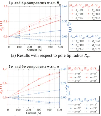
3.3. Effect with respect to pole shape
In order to check the effect with respect to pole shape on the separated field components, pole tip radius R pt was changed to 160, 168 and 173 mm, and cutting angle α was varied to 16 o , 20 o and 24 o . The results are represented in Fig. 5.
In Fig. 5, B sρ2 and B sρ6 are not changed since the position of coils is fixed, however B cρ2 and B cρ6 are varied by changing the pole tip radius R pt and the cutting angle α in the range of operating current. From the Fig. 5, we know that the signs of 2φ components and 6φ components are maintained by changing R pt and α i.e.
the signs of B sρ2 and B cρ2 are always same and the signs
c
s
B
B B = +
n c n s
n