-이충도: 교수
Received: Jul. 16, 2021 ; Revised: . Aug. 8, 2021 ; Accepted: . Aug. 17, 2021
†Corresponding author: ChoongDo Lee (Inha Technical College) Tel: +82-32-870-2181, Fax: +82-32-870-2517
E-mail: [email protected]
Journal of Korea Foundry Society 2021. Vol. 41 No. 5, pp. 434~444 http://dx.doi.org/10.7777/jkfs.2021.41.5.434 pISSN 1598-706X / eISSN 2288-8381
© Korea Foundry Society, All rights reserved.
This is an Open-Access article distributed under the terms of the Creative Commons Attribution Non-Commercial License (http://creative- commons.org/licenses/by-nc/3.0) which permits unrestricted non-commercial use, distribution, and reproduction in any medium, provided the original work is properly cited.
Al-xSi합금의 인장특성에 미치는 공정 Si입자의 파단과 미소기공율의 영향
이 충 도†
인하공업전문대학 금속재료과
Effects of Damage Evolution of Eutectic Si Particle and Microporosity to Tensile Property of Al-xSi Alloys
ChoongDo Lee†
Dept. of Metallurgical & Materials Engineering, Inha Technical College, Incheon 22212, Republic of Korea
초 록
본 연구에서는 미소기공과 Si석출상의 파단으로 구성되는 유효기공 면적분율에 대한 인장특성의 결함민감도 관점에서 Al-Si합금 의 인장특성을 공정 Si입자의 분포양상 변화에 대하여 평가하고자 하였다. Al-xSi(x=2,5,8,11)합금의 주방상태 미세조직인 망상구조 의 공정 Si입자는 T4처리를 통하여 과립형태로 변형시켰으며, CT분석과 주사전자현미경 관찰을 통하여 미소기공의 분포와 크기를 평가하였다. CT분석과 주사전자현미경의 비교분석을 통하여 인장변형과정에서의 균열성장이 최대 기공율을 포함하는 국부영역에서 발생함을 확인할 수 있었다. 그럼에도 불구하고 이들 분석방법에는 미소기공 인접영역에서의 소성변형집중과 미소기공의 분포양상에 의해 파생되는 실제적인 차이를 포함하기 때문에 정확히 일치된 결과를 얻을 수 없었다. 유효기공 면적분율의 변화에 대한 인장강 도와 연신율의 변화는 과립형태보다 망상구조 정출상의 분율변화에 더욱 민감한 의존도를 가진다.
핵심용어; 인장특성, 알루미늄합금, 미소기공율, 결함민감도, 공정 Si입자.
Abstract
This study investigated the overall dependence of the tensile properties of Al-Si alloys on the distribution aspect of a eutectic Si particle in terms of defect susceptibility to the effective void area fraction, referring to the sum of pre-existing microvoids and the damage evolution of the Si particle. The network morphology of as-cast Al-xSi (x=2,5,8,11) alloys was modified to a granular type via a T4 treatment, after which a computational topography (CT) analysis and scanning electron microscope (SEM) observations were utilized to evaluate the size and distribution of the microvoids. The CT and SEM analyses indicated that the main cracks grow along local regions that possess the highest porosity level. The local plastic deformation around the microvoids and the distribution aspect of the microvoids induced a practical difference between the iso-volumetric CT measurement and the SEM fractography out- comes. The results demonstrated that the overall dependence of the ultimate tensile strength (UTS) and elongation on the effective void area fraction is more sensitive to the variation of the area fraction of the Si particle in the network morphology than in the granular type; this is due to the sequential damage evolution of the neighboring Si particles in the eutectic Si colony.
Key words; Tensile property, Aluminum alloy, Microporosity, Defect susceptibility and Eutectic Si particle.
연구논문
1. Introduction
The casting alloys fabricated in conventional casting processes include small amounts of casting defects, such as microvoids and inclusions. In particular, the presence of microvoids in aluminum castings have been recognized as a fundamental factor causing the degradation of its overall tensile properties because it is intimately related to its metallurgical features, such as variation in hydrogen solubility, and volumetric change on solidification, unlike the inclusions, which can be practically removed by a drossing and skimming process in conventional foundries. The practical contribution and degradation of mechanical properties by the existence of microvoids were previously proposed by Herrera et al. [1] and Surappa et al. [2]; since then, various experimental and theoretical analyses on this topic have been conducted [3-8].
Among them, Gokhale et al. quantitatively described the power law dependence of tensile properties on the micro- porosity variation through the introduction of defect susce- ptibility concept in a logarithmic relationship between tensile elongation and fractographic porosity [5-7], i.e., the tensile elongation (e) of a material having a microporosity f can be expressed in terms of the defect susceptibility coefficient (m) and maximum elongation (eo) achievable in a defect-free condition (f = 0), as shown in Equation (1).
e = eo [ 1 – f ]m (1)
This approach was also introduced for a quantitative description of UTS on the microporosity variation as shown in Equation (2) [8-10].
S = So [ 1 – f ]n (2)
where S = and So are UTS of a material having microporosity f and the maximum UTS achievable in the defect-free condition (f = 0), respectively, and n is the defect susceptibility coefficient of UTS to microporosity variation.
In contrast, with respect to the contribution of the microstructural feature to the tensile deformation of the Al- Si alloy, Dighe et al. reported that the fracture path of A356 alloy depends on the geometric configuration and size distribution of the eutectic Si particle [7]. Additionally, Horstemeyer et al. proposed that the fracture behavior of the Al-Si alloy is affected by the damage evolution of the eutectic Si particle, which makes a practical change on
load-carrying capacity inside a material [11]. Therefore, the tensile property of the Al-Si casting alloy fundamentally depends on the damage evolution of the eutectic Si particle during plastic deformation as well as the stress concentration around the pre-existing microvoids exhibiting a dominant effect on the tensile deformation [11-16].
Recently, theoretical prediction using a modified constitu- tive model on tensile instability has been proposed with a practical contribution of damage evolution of the Si particle to the tensile property together with a fundamental effect of microporosity variation to the effective void area fraction [17]. Further, the reciprocal contribution of eutectic Si particle and microporosity can be described as the rule of a mixture based on the defect susceptibility coefficient [18, 19]. However, the additional contribution of geometric configuration of the eutectic Si particle, such as the continuous network morphology of the eutectic Si colony in as-cast condition by Sr-modification or the discontinuous granular type via T4 treatment, is still unclear; further, systematic studies on this field are limited.
Therefore, as a continuation of the previous studies, the present study aimed to investigate the relative contribution of the damage evolution of the eutectic Si particle in either the network morphology or granular type in terms of the defect susceptibility of tensile properties to effective void area fraction; which included the additional increment of void fraction by damage evolution and microporosity. This study also confirmed the fundamental contribution of microvoids to the tensile deformation through CT analysis and SEM fractography.
2. Experiments
2.1. Specimen preparation and microstructural ob- servation
In this study, the test specimens fabricated was an Al- xSi(x=2,5,8,11)-0.02%Sr alloy, and were prepared using the gravity casting process. The nominal composition of the Al-xSi alloys was controlled by the addition of an Al- 15wt.%Si master alloy, and the modification of the eutectic microstructures was achieved by the addition of 0.02 wt.%Sr using the Al-10%Sr master alloy. A melt of 1.8 kg was stabilized for 3 min at 730 oC after the addition of the master alloys, poured into a 5-step metallic mold (width:
120 mm; thickness: 5-25 mm; and length: 50 mm per each
thickness), and maintained at approximately 300 oC. The test specimens for microstructural observation and tensile tests were taken from a 15-mm-thick section [18, 19]. The post heat treatment was carried out for 72 h at 530 oC for spheroidization of individual Si particle, i.e., discontinuous granular morphology vs. continuous network morphology, which is a typical feature of the eutectic Si particle in the as-cast condition via Sr-modification.
Typical microstructural characteristics, such as the area fraction of the eutectic Si particle and the spacing between Si particles in eutectic Si colonies, were quantitatively measured using an optical microscope (OM). The microstructural analysis was based upon 5 views on each condition, and the area fraction of the eutectic Si particle and the spacing between Si particles were determined by a 2-color contrast image analyzer and the intercept line method (over 10 intercept lines per a view), respectively. The applied etchant was a Keller-type solution (2%HF + 3%HCl + 5%HNO3 + distilled water).
2.2. Tension test
Tensile specimens were fabricated as plate types with a gauge length of 30 mm and a width of 6 mm. Approximately 10 pieces were fabricated for each condition. The tension test was carried out at room temperature under a strain rate condition of 2.78 × 10⁻⁴ s−1 using a tensile testing machine (Instron 5985) with an optical extensometer (Instron 2663 model, advanced video extensometer). The yield strength (YS), UTS, and fracture elongation were selected as typical tensile properties, and the nominal value of YS was measured as the stress level at 0.2% offset strain.
2.3. CT analysis and microporosity measurement The nominal value of microporosity, size, and interspacing of individual microvoids in a tensile specimen was evaluated via CT analysis (GE Sensing & Inspection Technology, VtomeX L300 model). The overall contour of the microvoids on CT-scanned image corresponding to a fracture surface was compared to the fractographic morphology by SEM observation on the fractured surface after testing.
The microporosity was measured as fractographic porosity (area fraction of microvoids) by quantitative fractography analysis of SEM (JEOL JSM-5600 model) observations on the fractured surface of the entire test specimen; the value was expressed as the area ratio of the microvoids to the
entire area of the fractured surface.
3. Results
3.1. Microstructural characteristics
Fig. 1 shows typical micrographs of the T4-treated and as-cast Al-xSi alloys. The microstructural features of the T4-treated alloys are characterized as a form in which the individual Si particle of the discontinuous granular type are relatively uniformly dispersed throughout the matrix region (Fig. 1(a)–(d)), whereas the as-cast alloys can be depicted as network morphology of the eutectic Si particle around the Al-rich matrix (Fig. 1(e) and (f)). Additionally, the area fraction of the Si particle increases proportionally to the planar density of the Si particle regardless of the T4-treated or as-cast conditions.
The nominal values of the microstructural features on the variation of the Si content are listed in Table 1. The real area fraction of the eutectic Si particle increased from 1.8%
to 17.9% as the nominal Si content in the Al-xSi alloys increased from 2% to 11%. Additionally, the average spacing between the Si particles decreased substantially from 96.2 mm to 18.8 mm with the nominal Si content, whereas the average diameter of the individual Si increased slightly from 4.15 mm to 4.98 mm with the increase in the Si content.
3.2. Tensile properties
Fig. 2 depicts the overall dependence of tensile property with respect to the nominal Si amount in the T4-treated Al- xSi alloys; the detailed values of the tensile properties of the Al-xSi alloys are listed in Table 2. As shown, the YS and UTS increase from 45 MPa to 66 MPa and 99 MPa to 141 MPa, respectively, as the Si content is increased;
whereas, the tensile elongation gradually decreases from 14% to 11%. Additionally, the nominal value of the strength coefficient is increased from 217 MPa to 304 MPa as the Si content is increased, while the strain-hardening exponent gradually decreases from 0.30 to 0.26. Although the nominal range of UTS and elongation exhibits a considerable deviation from the average values as shown in Fig. 2 and Table 2, the overall level of tensile property in the T4- treated condition depends on the Si content, similar to the as-cast condition [17,18]. The main reason on this deviation is the difference in the fractographic porosity (area fraction of microvoids) among the tensile specimens as shown in Fig.
3, without considering the contribution of the microstructural transition by the Si content.
Fig. 3 shows the change in UTS and elongation of the Al-xSi alloys with respect to area fraction of microvoids.
As shown, the nominal level of UTS and elongation of both alloys significantly decrease as the microporosity
increases. In particular, the overall dependence of tensile elongation can be described by an inverse power law relationship with the microporosity variation, similar to those of the as-cast alloy [18,19]. Additionally, the overall level of tensile property exhibits a practical difference with respect to the alloy composition, even at same micro- Fig. 1.Microstructural views of Al-xSi alloys; (a) Al-2Si, (b) Al-5Si, (c) Al-8Si, and (d) Al-11Si alloys on T4-treatment with (e) Al-2Si and (f)
Al-11Si in as-cast condition.
Table 1. Microstructural feature of T4-treated Al-xSi alloys with respect to nominal variation of Si content Alloys
Microstructure 2Si 5Si 8Si 11Si
Nominal area fraction of eutectic Si particle (%) 1.76 7.32 12.61 17.93
Spacing between Si particles (µm) 96.2 30.8 25.0 18.8
Individual diameter of Si particle (µm) 4.15 4.72 4.83 4.98
porosity. The UTS and elongation of the Al-2Si and Al- 11Si alloys for the area fraction of microvoids of 15%
indicate a practical difference of approximately 40 MPa and 11%, respectively.
Fig. 4 shows the overall dependence of UTS and tensile elongation on the microporosity variation as a linear relation- ship, in terms of the defect susceptibility coefficient (slope of regression line) and maximum values achievable in a defect-free condition (intercept with y-axis) [4,5.7-9]. The defect susceptibility coefficients of both UTS and elongation Fig. 2.Tensile properties of a nominal alloy composition of Al-xSi
alloys.
Table 2. Tensile properties of the Al-xSi alloys with respect to nominal variation of Si content Alloys
Property
2Si (+/-)
5Si (+/-)
8Si (+/-)
11Si (+/-)
YS (MPa) 44.7 (3.3/2.7) 55.7 (6.1/5.9) 65.5 (4.5/3.5) 66.3 (4.7/5.3)
UTS (MPa) 99.0 (11.2/7.0) 121.0 (16.3/12.1) 136.9 (12.1/25.9) 147.1 (17.9/10.1)
Elongation (%) 14.1 (6.4/4.5) 13.8 (3.5/7.2) 13.2 (5.8/9.2) 11.2 (4.2/3.8)
Strength coefficient (MPa) 216.8 (8.2/10.5) 253.4 (6.5/7.8) 295.5 (8.0/9.2) 304.2 (5.7/4.3) Strain-hardening exponent 0.30 (0.01/0.01) 0.28 (0.01/0.01) 0.27 (0.01/0.02) 0.26 (0.01/0.01) Fractographic porosity (%) 0.263 (0.121/0.163) 0.211 (0.148/0.066) 0.154 (0.209/0.104) 0.111 (0.060/0.048) Fig. 3.Overall dependence of UTS and elongation on area fraction
of microvoids in the Al-2Si and Al-11Si alloys.
Fig. 4.Overall dependence of (a) UTS and (b) elongation to microporosity variation for Al-xSi alloys in terms of defect susceptibility.
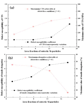
with respect to the area fraction of the Si particle are depicted in Fig. 5 with the maximum values of both tensile properties achievable under a defect-free condition. As shown, the defect susceptibility coefficient of elongation exhibits an obvious difference in the variation of the area fraction of the Si particle, even though the UTS demonstrated only a slight increase with the area fraction of the Si particle. Additionally, the maximum values of UTS and elongation indicate a remarkable variation with respect to the area fraction of the Si particle; i.e., the maximum UTS increases from 120 MPa to 160 MPa, whereas the nominal maximum value of elongation decreases from 28% to 19%
as the area fraction of Si particle increases.
3.3. Computational topography and SEM fractography Fig. 6 shows a typical appearance of the fractured specimen, the iso-image by CT analysis, and the distributional frequency of the projected area of the microvoids in a gauge length of the Al-5Si and Al-11Si alloys. It was evident from the CT analysis that the microvoids in both specimens were uniformly distributed along the gauge length, and the nominal level of microporosity in Al-5Si alloy was higher than that of Al-11Si alloy. Additionally, the fractured position Fig. 5.Defect susceptibility coefficient to microporosity variation
and maximum value of tensile properties achievable at defect-free condition for nominal area fraction of the eutectic Si particle; (a) UTS and (b) elongation.
Fig. 6.Comparison of CT-scanned and actual fractured images on frequency distribution of the total projected area along axial direction of the tensile specimen; (a) Al-5Si and (b) Al-11Si alloys.
in both specimens corresponds to a region where a cluster of microvoids is locally concentrated. This is because the main path on crack growth and coalescence between the neighboring microvoids is restricted to a specific region of gauge section having a relatively high microporosity.
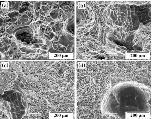
Fig. 7 shows the microscopic views of the fractured surfaces obtained via SEM observation. As shown, the fractured morphology of the Al-2Si alloy comprises the ductile fracture around the Al-rich matrix and the interdendritic shrinkage voids that are widely distributed over the entire fractured surface. In contrast, the Al-11Si alloy exhibited typical microvoids of blowhole type, which are formed from the coalescence of gas dissolved in a melt. Additionally, the overall contour of the fractured surface that corresponds to the damage evolution of individual Si particle in the eutectic Si colony became more dominant as the nominal Si content increased, even though the fractured morphology of the alloys with low Si content is mainly comprised a ductile fractured mode with a dimple fracture of the Al-rich matrix.
4. Discussion
4.1. Microporosity on tensile properties
As shown in Fig. 6, the macroscopic crack growth of the
Al-xSi alloy was achieved by void coalescence between neighboring microvoids in a local region of high porosity level of tensile specimen, and the nominal fractured position corresponded to a gauge section that has the highest porosity level.
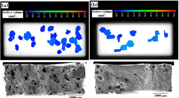
Fig. 8 shows the comparison between the cross-sectional CT-scanned images for an iso-volume of a fixed thickness (1.5 mm around fractured position) before the tensile test and SEM fractographic images of the fractured surface after the tensile test. As shown, the detail description of individual size and position of the microvoids between both images exhibits a practical difference, particularly for a cluster of small-sized microvoids, even though nominal size and geometric configuration of microvoids in CT-scanned image are relatively in good agreement with those of the SEM images. The CT-scanned image is iso-volumetric, and the planar segment is vertical to the axial direction of the tensile specimen before the tensile test, while the SEM image corresponds to the actual fractured surface that practically deviated from a plane normal to the tensile axis during the tensile deformation.
A small difference between both analyses was observed as the plastic deformation on the tensile test was accompanied by the accumulation of local plastic deformation around the Fig. 7.Macroscopic SEM views of the fractured surface for the Al-xSi alloys; (a) Al-2Si, (b) Al-5Si, (c) Al-8Si, and (d) Al-11Si alloys.
microvoids, and the crack growth deviated from a specific plane normal to tensile axis though the sequential coalescence between the neighboring microvoids.
However, given that the crack growth under tensile loading is achieved along a region having maximum micro- porosity, which corresponds to a minimum level of load- carrying capacity inside a material, the nominal value of the fractographic porosity reaches to a high level of approximately 40% at maximum as shown in Fig. 3.
4.2. Damage evolution of the Si particle on tensile deformation
SEM fractography in Fig. 7 shows that the damage evolution of the Si particle in the fractured surface becomes more noticeable with the increase in the area fraction of the Si particle. The general trend on the damage evolution of the Si particle with respect to the variation in the area fraction of the Si particle is clearly demonstrated in the cross- sectional observation of tensile specimen.
Fig. 9 shows a typical microstructural image of the deformed region adjacent to the fractured section of the Al-2Si and Al-11Si alloys in the T4-treated and as-cast conditions. As shown, the tensile fracture of the T4-treated alloys was achieved through the penetration of the Al-matrix region, with local distribution of the damage evolution by cracking of the Si particle or by debonding between the Si particle
and Al-matrix (Fig. 9(a)). The occurrence frequency of the damage evolution in the Al-11Si alloy (Fig. 9(c)) was higher than that of the Al-2Si alloy as demonstrated by the decrease of interspacing between the individual Si particles and the increase of the area fraction of the Si particle.
However, the damage evolution of the Si particle in as-cast alloy is more remarkable than the T4-treated alloy (Fig. 9(b) and (d)), and its typical fracture path was characterized by the sequential fracture of individual Si particle in the Si colony of network morphology, accompanied by the penetration of Al-matrix region only in the local region.
Thus, the crack growth in Al-rich matrix of the Al-Si as- cast alloy is achieved with the sequential damage evolution of Si particle after the crack initiation at a local region of high porosity level. The occurrence frequency of the damage evolution of the Si particle primarily depends on the interspacing between individual Si particles, without regard to whether the precipitation mode of Si particle is in granular or network morphology. In particular, the occurrence frequency of the damage evolution in the as-cast Al-11Si alloy (Fig. 9(d)) is evidently increased, compared with the T4-treated Al-11Si alloy (Fig. 9(c)). This is because the interspacing between the individual Si particles in the eutectic Si colony of the as-cast Al-11Si alloy is drastically decreased with a remarkable decrease in the size of the individual Si particle even though both alloys had similar Fig. 8.Cross-sectional CT-scanned images before tensile test and SEM fractographic observation of fractured surface after tensile test of same
tensile specimens (a) Al-5Si and (b) Al-11Si alloys.
level of the area fraction.
The occurrence frequency of the damage evolution of the Si particle can be described in terms of incoherency parameter by the combination of local microscopic strain for the damage evolution of Si particle (ef*) to macroscopic strain of a material (ei) as shown in following Equation (3) [17,20].
h = (ei− ef*) / ei (3)
Therefore, the effective void area fraction of the Al-xSi alloy that includes the pre-existing microvoids, can be expressed as following Equation (4), with the introduction of the incoherency parameter to the area fraction of the Si particle. However, the local microscopic strain for the damage evolution of the eutectic Si particle is apparently lower than that of the macroscopic fracture strain (ei > ef*).
Additionally, given that the damage evolution of the Si particle in a granular type is delayed compared to that of the network morphology (ef*
_granular > ef*
_network), the nominal magnitude of the incoherency parameter of the Si particle in the granular type is relatively lower than that of the network morphology (h_granular < h_network).
feffec. void area frac.
= fmicrovoid + hSi-particlefSi-precipitate
= fmicrovoid+ hSi-granularfSi-granular+ hSi-networkfSi-network (4)
4.3. Microporosity and damage evolution of preci- pitate on defect susceptibility
Given that the load-carrying capacity of the Al-xSi casting alloy under tensile loading practically depends on the variation of effective void area fraction, which is the combination of individual contributions of pre-existing microvoids and damage evolution of the Si particle, the overall dependence of tensile properties on the effective void area fraction shown in Equation (1) and (2) can be re- written as the following equations (5a & 5b).
e = eo [ 1 – f effec. void area frac. ]m’
= eo [ 1 – (f microvoid +hSi-particlefSi-particle)]m’ (5a) S = So [ 1 – f effec. void area frac. ]n’
= So [ 1 – (f microvoid +hSi-particlefSi-particle) ]n’ (5b) The graphic description of the defect susceptibility of tensile property on the microporosity variation shown in Fig.
4 can be expressed as in Fig. 10 in terms of the effective Fig. 9.Typical images for deformed microstructure of fractured specimen (a, b) Al-2Si and (c, d) Al-11Si; (a, c) T4-treated and (b, d) as-cast
condition.
void area fraction. As shown, the effective void area fraction is the combination of the individual contribution of the distribution aspect of the Si particle and the fundamental contribution of the pre-existing microvoids. Additionally, the T4-treated Al-2Si alloy represents only a typical microstructure of the Al-rich matrix because it has significantly low area fraction of the Si particle in the granular type, i.e., it is different only on the area fraction of the Si particle compared with the T4-treated Al-11Si alloy. Furthermore, the only practical difference between the as-cast and T4-treated Al- 11Si alloys is their morphology, i.e., granular or network, because the area fraction of the Si particle is at a very similar level.
As shown in Fig. 10(a), the defect susceptibility coefficient of the UTS does not practically depend on the difference between the area fraction of the Si particle of the Al-2Si and Al-11Si alloys; the defect susceptibility coefficient of the Al-2Si alloy fundamentally depends on the microporosity variation. This means that the individual contribution of the damage evolution of the Si particles to UTS is not practical
even though the network morphology of the Si particle has a relatively dominant effect on the increment of UTS (DSSi-network morph.) on the effective void area fraction compared to the granular type (DSSi-granular.).
Meanwhile, Fig. 10(b) indicates that the overall dependence of tensile elongation on the effective void area fraction is more sensitive than that of UTS. The additional contribution of the area fraction of the Si particle (DfSi-particle) becomes more dominant with the increase in the effective void area fraction, even though the microporosity term has a significant role in the overall dependence of tensile elongation on the effective void area fraction. Additionally, the network mor- phology has higher contribution than that of the granular morphology (DfSi-granular morph. < DfSi-network morph.). This is due to the fact that the damage evolution of the network morphology occurs continuously through the sequential fracture between the neighboring small Si particles in the eutectic Si colony.
5. Conclusion
(1) The main path of crack growth on the tensile deformation is by the coalescence between local regions that have nominally high porosity level in the gauge section. Additionally, the accumulation of local plastic deformation around the microvoids and a practical change on the fracture path by the distribution frequency of the pre-existing microvoids makes a practical deviation between the iso-volumetric CT measurement and SEM fractography, even though the CT analysis suggests a fractured position of the tensile specimen through the measurement of geometric configuration and size distribution of the pre-existing microvoids.
(2) The additional contribution of the damage evolution of the Si particle to the effective void area fraction practically influences the tensile elongation, rather than U T S , e v e n though its nom inal level is relatively underestimated compared to the fundamental contribution of the pre-existing microvoids. The overall dependence of UTS and elongation on the effective void area fraction is more sensitive to the variation in area fraction of the Si particle in network morphology than in granular type; it is due to the sequential damage evolution of the neighboring Si particles in the eutectic Si colony. In addition, in granular morphology, the increase in area fraction of the Si particle induces a practical increase in the effective void area Fig. 10.Relative contribution of damage evolution of precipitates
and microporosity to defect susceptibility of UTS (a) and elongation (b) in terms of effective void area fraction.
fraction by the increase of occurrence frequency of damage evolution of the Si particle.
(3) In terms of the defect susceptibility coefficient and maximum values of tensile properties achievable in a defect- free condition, the variability in the tensile property of the Al-xSi alloys can be described as a linear relationship with the effective void area fraction, which fundamentally depends on the microporosity variation, including the additional contribution of damage evolution of the Si particle irrespective of the type of morphology (granular or network). Additionally, the defect susceptibility coefficient of UTS and elongation to the variation of effective void area fraction increases with the area fraction of the Si particle. The maximum UTS achievable in a defect-free condition increases with the area fraction of the Si particle, whereas the maximum tensile elongation decreases remarkably as the area fraction of Si particle increases.
Acknowledgements
This research was supported by Inha Technical College Research Grant in 2020.
References
[1] A. Herrera and V. Kondic, Proc. Int. Conf. on Solidification and Cast Metals, The Metal Society, Sheffield, (1977) 460- 473.
[2] M. K. Surappa, E. Blank and J. C. Jaquet, Scr Metall., 20(9) (1986)1281.
[3] C. H. Cáceres, Scr Metall., 32(11) (1995) 1851.
[4] C. H. Cáceres and B. I. Selling, Mater Sci Eng A, 220(1-2) (1996) 109.
[5] A. M. Gokhale and G. R. Patel, Mater Charac., 54(1) (2005) 13.
[6] A. M. Gokhale and G. R. Patel, Mater Sci Eng A, 392(1-2) (2005) 184.
[7] M. D. Dighe and A. M. Gokhale., Scr Mater., 37(9) (1997) 1435.
[8] C. D. Lee, Mater Sci Eng A, 464(1-2) (2007) 249.
[9] C. D. Lee, Mater Sci Eng A, 488 (1-2) (2008) 296.
[10] C. D. Lee, Mater Sci Eng A, 527(13-14) (2010) 3144.
[11] M. F. Horstemeyer and A. M. Gokhale, Inter J of solids and struct., 36 (1999) 5029.
[12] M. F. Horstemeyer, J. Lathrop, A. M. Gokhale and M. D.
Dighe, Theoretical applied fracture mechanics, 33(1) (2000) 31.
[13] J. P. Bandstra, D. M. Goto and D. A. Koss, Mater Sci Eng A, 249(1-2) (1998) 46.
[14] J. Gammage, D.Wilkinson, Y. Brechet and D. Embury, Acta Mater., 52(18) (2004) 5255.
[15] G. Huber, Y. Brechet, T. Pardoen, Acta Mater., 53(9) (2005) 2739.
[16] W. J. Poole and N. Charra, Mater Sci Eng A, 406(1-2) (2005) 300.
[17] C. D. Lee, K. S. Shin and Y. J. Kim, Eng Mater Frac., 175 (2017) 339.
[18] C. D. Lee, J. I. Youn, Y. G. Lee and Y. J. Kim, Mater. Sci. Eng.
A, 678 (2016) 227.
[19] C. D. Lee, J. I. Youn, Y. G. Lee and Y. J. Kim, Inter. J. Met.
Cast., 11(1) (2017) 84.
[20] W. J. Poole and N. Charra, Mater. Sci. Eng. A, 406(1-2) (2005) 300.