Journal of Magnetics 22(2), 291-298 (2017) https://doi.org/10.4283/JMAG.2017.22.2.291
© 2017 Journal of Magnetics
External Magnetic Field of Journal Bearing with Twined Solenoid
Yanjuan Zhang1, Jianmei Wang2*, and Decai Li1,3*
1School of Mechanical, Electronic and Control Engineering, Beijing Jiaotong University, Beijing, China 2College of Mechanical Engineering, Taiyuan University of Science and Technology, Taiyuan, China
3CountryState Key Laboratory of Tribology, Tsinghua University, Beijing, China
(Received 20 January 2017, Received in final form 2 April 2017, Accepted 4 April 2017)
In this paper, the distribution of internal magnetic induction intensity of oil-film bearing twined solenoids was proposed. The magnetic field was generated by solenoids and magnetized bearing. The magnetized bearing was simplified as solenoid model. The mathematical model of magnetic induction intensity at any point of finite solenoid was deduced. Through experiment method, the distribution of the internal magnetic induction inten-sity of oil-film bearing and the magnetizing current formula of bearing was obtained. Further, the magnetic induction intensity distribution of magnetization bearing was solved successfully. The results showed that the magnetic induction was a second-degree parabola with open upwards along the axial plane and the distribu-tion of magnetic inducdistribu-tion intensity was opposite to the rule of magnetic inducdistribu-tion intensity generated by sole-noids. In addition, the magnetic flux density increased linearly with the increase of current.
Keywords : solenoid, magnetic field, magnetizing current
1. Introduction
As the key component of mechanical transmission, the bearing plays a vital role. Both the increase of temperature and bearing capacity would reduce the oil-film thickness of load area, and likely lead to friction or wear in contact areas between shaft and bearing. More seriously, it could lead to bearing failure and the actual production halt. Using magnetic liquid to lubricate bearing would help to improve the performance of bearing under the same condition. But the bearing performance was closely related to the magnetic induction intensity distribution. There-fore, studying the distribution of magnetic field in the inside of oil film bearing was crucial to improve bearing performance.
Up to now, many experts and scholars have made a lot of researches on ferrofluids lubrication under magnetic field. The study proposed by Tze-Chi Hsu et al. [1] indicated that magnetic field has a significant influence on the lubrication performance of short journal bearings. The work of T. A. Osman [2] showed that the bearing
performance mainly depends on the magnetic field di-stribution model at low eccentricity ratios. It follows that external magnetic field had a very important influence on journal bearings lubricated with ferrofluid. So some researchers conducted research on the distributed regularity of magnetic induction intensity.
Har Prashad [3] studied the magnetic flux density on the inner and outer surfaces of the inner race and outer race of a rolling bearing. Huang W. et al. [4] analyzed the ferrofluids lubrication with an external magnetic field, and the results showed that the magnetic field intensity distribution on the rubbing surface has a significant influence on tribological properties of ferrofluids. Jianmei W. et al. [5] used solenoid model to provide magnetic field for ferrofluids and preliminarily calculated the distribution of magnetic induction intensity. Aritro Pathak [6] had provided a quantitative analysis for the field outside the solenoid and explained how the magnetic field behaves outside a uniform current density solenoid. Al-Shaikhli A. K. et al. [7] presented the axial and radial magnetic field strength equations at any point inside or outside a finite solenoid with infinitely thin walls. The axial magnetic field of pulsed solenoids was also analyz-ed by J. Novickij et al. [8]. Foelsch K. [9] calculatanalyz-ed the distribution of magnetic field within a certain distance to the axis. Melody Xuan Lim and Henry Greenside [10]
©The Korean Magnetics Society. All rights reserved. *Corresponding author: Tel: +010-13651206606(Decai Li), +010-18635149106(Jianmei Wang)
Fax: +010-51685265, e-mail: [email protected](Decai Li), [email protected](Jianmei Wang)
used superposition and numerical approximations of an analytical expression to study the magnetic field gene-rated by a finite solenoid and showed how the magnitude and uniformity of the resultant external field depend on the solenoid length and distances between solenoids. Fujiwara K. et al. [11] studied the continuity of the mag-netizing current density in 3-D magnetic field analysis with edge element.
The above literatures mostly concentrated on the separate study of magnetic field. Hossein Vahid Alizadeh and Benoit Boulet [12] presented an analytical calculation method to compute the magnetic vector potential of an axisymmetric solenoid in the presence of an iron shield and a ferromagnetic core.
However, most of the above studies are theoretical research and lacking necessary experiment. Moreover, they didn’t study the magnetic induction intensity di-stribution of oil-film bearing twined solenoids. In this study, the mathematic model of magnetic induction intensity distribution inside the journal bearing twined solenoids was further completed, and the magnetization current formula of bearing magnetized was deduced. Then the distribution of magnetic field, which is gene-rated by exciting field of solenoid and derived field of bearing, was numerically and experimentally studied.
2. Theoretical Research
Figure 1 is the schematic diagram of bearing with twined finite solenoid. The bearing will be magnetized, and the magnetized current will be produced when the current flows through solenoid coil. The magnetic induc-tion intensity of bearing is consisted of exciting field generated by solenoid and derived field produced by the magnetized bearing. The magnetized bearing is regarded as a secondary field source.
2.1. Derivation of Finite Solenoid Equations
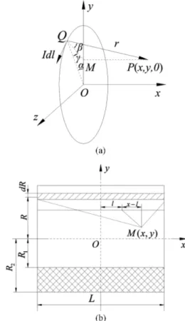
Considering a solenoid as shown in Fig. 2, the magnetic induction intensity of an arbitrary point outside single coil is derived according to Biot-Savart law, the schematic diagram of single coil is given in Fig. 2(a). The schematic diagram of multi-turn solenoid model is shown in Fig. 2(b).
In Fig. 2(a), the center of coil is viewed as the origin point O to create Cartesian coordinate system. The differential form of magnetic induction intensity of any point P outside the coil is obtained on the basis of Biot-Savart law, which can be given as follows.
(1) where, I : Current in single coil (A);
μ0 : Vacuum permeability;
r : The Distance of any point Q on the coil to point P; r0 : Unit vector of Idl to any point P;
According to the geometric relationships in Fig. 2(a), the formula (1) is developed as follows:
0 1
4
2Id
d
r
μ
π
×
=
⋅
l r
0B
(
)
0 1 3 2 2 2 2cos cos cos sin sin sin
4 -2 cos IR d d x R y Ry μ β γ α β α β α π α + + = ⋅ + + i j k B
Fig. 1. The schematic diagram of producing magnetic field in the inner of bearing.
Fig. 2. The theoretical calculation model. (a) Schematic dia-gram of single coil. (b) Schematic diadia-gram of multi-turn sole-noids
(2) where, α : Angle between line OM and the Y-axis
β : Angle between line MQ and line PQ γ : Angle between line OQ and line MQ
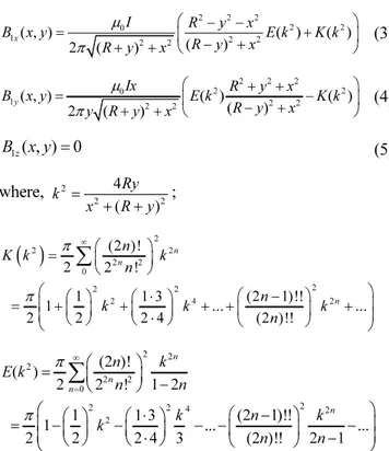
Here, dB1 is decomposed in Cartesian coordinate system. Then the first and second complete elliptic integral are used to get the magnetic induction intensity along three directions. Due to the symmetry feature of coil, the magnetic induction intensity at any point P only has two components of x direction and y direction, and the component of z direction is zero.
(3)
(4)
(5) where, ;
According to Biot-Savart law and the first and second complete elliptic integral, the magnetic induction intensity of solenoid along axial and radial directions at any point can be deduced.
Due to the symmetry feature of coil, the magnetic induction intensity at any point only have two compo-nents of x direction and y direction, and the component of z direction is zero. The equation of axial magnetic induction intensity B0x(x, y) is shown as follows:
(6)
In the same way, the radial magnetic induction intensity B0y(x, y) is derived:
(7)
B0y(x, y) = 0 (8)
where, L : Width of bearing (mm); R1 : Inner radius of solenoid (mm); R2 : Outer radius of solenoid (mm);
n1, n2 : Number of turns at per unit length and thickness of the solenoid;
μ0 : Vacuum permeability.
Compared with the axial magnetic induction intensity, the axial magnetic induction intensity is considerably larger than radial magnetic induction intensity. So, the influence of radial magnetic induction intensity would be ignored.
2.2. Magnetizing current of bearing
The charged particles in the bearing would be ordered under external magnetic field, and the magnetizing current would be produced as well as the magnetic field. At present, the research about magnetizing current was concentrated on magnetic materials and hysteresis loop [13-15]. However, the study for magnetic current on the surface of bearing was little. According to the derived field of magnetized bearing, the bearing can be simplified as solenoid model with coils, as shown in Fig. 3. The mathematical model is used to calculate magnetic induc-tion intensity produced by bearing. Due to the uneven distribution of magnetic field generated by the finite solenoid, the distribution of magnetizing current of bear-ing is also not uniform. Accordbear-ing to the theoretical
2 2 2 2 2 0 1 ( , ) 2 2 ( )2 2 ( ) ( ) 2 ( ) ⎛ − − ⎞ = ⎜ + ⎟ − + + + ⎝ ⎠ x I R y x B x y E k K k R y x R y x μ π 2 2 2 2 2 0 1 ( , ) 2 2 ( )( )2 2 ( ) 2 ( ) ⎛ + + ⎞ = ⎜ − ⎟ − + + + ⎝ ⎠ y Ix R y x B x y E k K k R y x y R y x μ π 1z( , ) 0= B x y 2 2 2 4 ( ) = + + Ry k x R y
( )
2 2 2 2 2 0 2 2 2 2 4 2 (2 )! 2 2 ! 1 1 3 (2 1)!! 1 ... ... 2 2 2 4 (2 )!! ∞ ⎛ ⎞ = ⎜ ⎟ ⎝ ⎠ ⎛ ⎛ ⎞ ⎛ ⋅ ⎞ ⎛ − ⎞ ⎞ ⎜ ⎟ = ⎜ +⎜ ⎟ +⎜ ⎟ + +⎜ ⎟ + ⎟ ⋅ ⎝ ⎠ ⎝ ⎠ ⎝ ⎠ ⎝ ⎠∑
n n n n K k k n n k k k n π π 2 2 2 2 2 0 2 2 2 4 2 2 (2 )! ( ) 2 2 ! 1 2 1 1 3 (2 1)!! 1 ... ... 2 2 2 4 3 (2 )!! 2 1 ∞ = ⎛ ⎞ = ⎜ ⎟ − ⎝ ⎠ ⎛ ⎛ ⎞ ⎛ ⋅ ⎞ ⎛ − ⎞ ⎞ ⎜ ⎟ = ⎜ −⎜ ⎟ −⎜ ⎟ − −⎜ ⎟ − ⎟ ⋅ − ⎝ ⎠ ⎝ ⎠ ⎝ ⎠ ⎝ ⎠∑
n n n n n k E k n n k n k k n n π π 2 1 /2 0 1 2 0 - /2 2 2 2 2 2 2 2 2 2 n n ( , ) 2 ( ) ( ) ( ) ( ) ( ) ( ) ( ) = + + − ⎛ − − − + ⎞ ⎜ − + − ⎟ ⎝ ⎠∫ ∫
L R x L R I B x y r y x l r y x l E k K k drdl r y x l μ π 2 2 /2 R 0 1 2 0 /2 R 2 2 2 2 2 2 2 2 2 ( )n n ( , ) 2 ( ) ( ) ( ) ( ) ( ) ( ) ( ) − − = + + − ⎛ + + − − ⎞ ⎜ − + − ⎟ ⎝ ⎠∫ ∫
L y L I x l B x y y r y x l r y x l E k K k drdl r y x l μ πcalculation of magnetic flux density distribution of practical solenoid coil and experimental measurement of its magnetic flux density, the formula on magnetizing current was preliminarily got and amended.
As shown in Fig. 3, according to the theory of elec-tromagnetics, a closed loop abcd in the magnetic field is arbitrarily chosen, which contained excitation current I and magnetizing current Ic(x, y). On the basis of Ampere's law, the relationship between magnetic field B and the current in the closed loop is as follows.
(9) Using magnetizing current Ic(x) to replace current I in formula (6), the magnetic induction intensity Bc(x, y) generated by the derived field is got.
(10)
where, R3, R4 : Inner and outer radius of bearing (mm); n3, n4 : Number of turns at per unit length and thickness
of bearing simplified as solenoid model, n3= M/ L, n4= N/(R4-R3);
According to the superposition principle of magnetic field, the magnetic flux density B (x, y) at any point in the inner wall is as follows:
(11)
3. Experimental Study
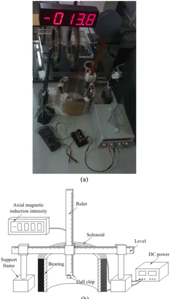
The experimental device to measure magnetic induction intensity of the inner wall of bearing winded solenoid is shown in Fig. 4. The device is based on the principle that the movement of charged particles will produce deflection under Lorenz force and magnetic field. This deflection will make the charged particles that are constrained within solid material produce the accumulation of positive and negative charges along the vertical direction of mag-netic field, thus forming an additional transverse magmag-netic field, i.e., that is Hall electric field.
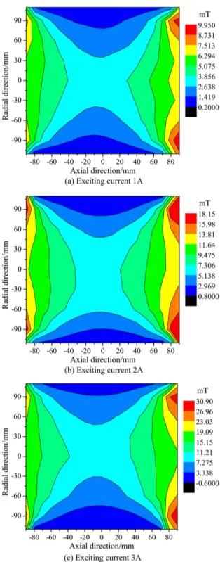
Using the measurement device, magnetic flux density distribution could be respectively given when the excita-tion current in solenoid respectively was 1A, 2A and 3A. The distribution of magnetic induction intensity with different exciting current is shown in Fig. 5.
Figure 5 shows the shape of magnetic induction inten-sity distribution inside the solenoid. The magnetic
induc-tion intensity increases with the increase of exciting current. The magnetic induction intensity is gradually increasing along the axial symmetry plane to the end of bearing, which is opposite to the rule of magnetic induc-tion intensity generated by single solenoid. So, it can be concluded that the derived field generated by magnetized bearing is contrary to the excitation field produced by solenoid. The magnetic induction intensity gradually increases firstly and then decreases from the radial sym-metry plane to the inner wall of bearing. In the inside of bearing, the change of magnetic flux density becomes relatively average; but at the ends of bearing, the change displays larger. The reason for this phenomenon is that the influence of current on end region of bearing is more significant than that on other regions. That is, the
mag-0 ( ( )) = ⋅
∑
+∫
abcdBdl µ abcd I I xc 4 3 /2 0 3 4 - /2 2 2 2 2 2 2 2 2 2 ( )n n ( 2 ( ) ( ) ( ) ( ) ( ( , ( ) ) ) ) = + + − ⎡ − − − + ⎤ ⎢ − + − ⎥ ⎣ ⎦∫ ∫
L R c c L R I x B r y x l r y x l E k x y K k drdl r y x l μ π 0 , ) , ) , ) ( ( ( x x y x x y Bc y B =B + xFig. 4. (Color online) The experimental device. (a) Realistic measurement device. (b) Principle diagram of experimental device
netic flux density of each part increases linearly with the increasing current, but it increases more at the end region of bearing.
4. Numerical Solution
At present, there is less research about magnetizing current of bearing. According to experimental magnetic flux density distribution of bearing and the superposition principle of magnetic field, the distribution of magnetic induction intensity that is only produced by magnetized bearing could be obtained. The amended magnetizing current formula is got through the fitting of magnetizing current along axial direction with the bearing being simplified as solenoid model, and the distribution shape is a parabola going downwards. The diagram of magnetiz-ing current is shown in Fig. 6.
Figure 6 presents the magnetizing current linearly
Fig. 5. (Color online) The experimental distribution of mag-netic induction intensity.
Fig. 6. (Color online) The diagram of magnetizing current and the fitted curves under different exciting current.
increases with the increasing of exciting current. Accord-ing to the fittAccord-ing of magnetizAccord-ing current under different exciting current in Fig. 6, the fitting equation could be got.
(12)
Where, m, n, p : Coefficients related to the intensity of magnetization and the exciting current.
According to the formulas stated in Equation (6), (10), (11), (12) and numerical model, the flow chart of numerical solution to magnetic flux density was shown in Fig. 7.
When the exciting current is 1A, 2A and 3A separately, the axial magnetic induction Bx in the inner of bearing calculated is shown in Fig. 8.
Figure 8 reflects the overall distribution of axial mag-netic flux density by numerical solution, which is relative-ly stable and symmetrical to the axial plane of symmetry and the radial plane of symmetry of the model.
5. Results and Discussion
The further study of the internal magnetic induction intensity of oil-film bearing twined solenoid demonstrates that the calculated results agree with the experimental results essentially.
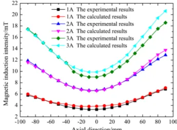
Figure 9 provides the distribution of magnetic induction intensity at the central axis of bushing, whose form a parabola is going upwards.
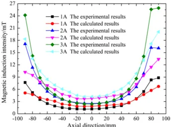
Figure 10 gives the distribution of magnetic induction intensity at the inner-wall of bushing. The distribution of magnetic flux density on the middle is uniform and has significant edge effect.
Through the analysis on experimental results in Fig. 9 and theoretical results in Fig. 10, we can get the fitted curves of theoretical values with experimental results, which can verify the reasonableness of magnetizing current model. Both results display end effect, the reason may be that the edge of bearing causes the divergence of mag-netic field lines. The divergence makes the magmag-netic field
2
( )
c
I x =mx +nx p+
Fig. 8. (Color online) The theoretical value distribution of magnetic induction intensity.
Fig. 9. (Color online) The distribution of magnetic induction intensity at the central axis.
lines in per unit area increase, that is to say, the magnetic induction intensity increases.
When extracting the axial magnetic induction intensity of bearing with the exciting current is 1A, 2A and 3A, the relative errors between theoretical values and experimental values is shown in Fig. 11.
Figure 11 shows the absolute error and relative error between the experimental results and calculated results. The figure revealed that the theoretical distribution of magnetic induction intensity is basically consistent with the experimental distribution, which validated the reason-ableness of theoretical model and experimental method. And the maximum error between the two results was astonishingly less than 10%. So, the results from practical data have confirmed the reliability of this algorithm that magnetized bearing was simplified as solenoid model.
Considering the thickness of oil film is thinner (thick-ness generally less than 1 mm) and the magnetic fluid is mainly located in the wedge-shaped gap between bearing
and shaft, the actual measurement such as magnetic induction intensity distribution in the gap is very difficult. So this numerical method can be used to solve the axial magnetic flux density within the range of 1mm from the inner wall of bearing in future study.
6. Conclusions
Conclusions could be briefly listed as follows:
1) A new method was proposed for studying the axial magnetic flux density of journal bearing with twined solenoids in this paper, which provided the basis and help for further explore on relevant issues or beneficial reference for other researchers.
2) The magnetizing current of bearing was obtained in this paper, which provided theoretical support for the further study with high application value.
3) The axial magnetic flux density Bx is basically sym-metrical to the axial plane of symmetry, which is a second-degree parabola going upwards along radial direction? and the magnetic flux density linearly increases with the increase of exciting current.
4) The theoretical results fitted well with experimental results, which proved the reasonableness of theoretical model that bearing was simplified as solenoid is reason-able.
Acknowledgements
This work was supported by the Shanxi Provincial Natural Science Foundation of China (No. 201601D011049) and the Program for Changjiang Scholars and Innovative Research Team (grant no. IRT13046), the Shanxi Province special patent to promote implementation of the funds of China (No. 20161005), the Shanxi Provincial Key Research and Development Project (No. 201603D111017), and the National Science Foundation of China (No. U1610109 and 51505475).
References
[1] T. Hsu, J. Chen, H. Chiang, and T. Chou, Tribol. Int. 61, 169 (2013).
[2] T. A. Osman, G. S. Nada, and Z. S. Safar, Tribol. Lett. 14, 11 (2003).
[3] H. Prashad, Tribol. Int. 32, 455 (1999).
[4] W. Huang, C. Shen, S. Liao, and X. Wang, Tribol. Lett. 41, 145 (2011).
[5] W. Jianmei, K. Jianfeng, Z. Yanjuan, and H. Xunjie, Tri-bol. Int. 75, 61 (2014).
[6] A. Pathak, Eur. J. Phys. 38, 1 (2016).
[7] A. K. Al-Shaikhli, K. O. H. Fatima, and J. L. A. Fadhil, Fig. 10. (Color online) The distribution of magnetic induction
intensity at the inner-wall.
Circuits and Systems 4, 316 (2013).
[8] J. Novickij, R. Kačianauskas, and A. Kačeniauskas, Elek-tron. Elektrotech. 2, 15 (2004).
[9] K. Foelsch, Archiv für Elektrotechnik 3, 139 (1936). [10] M. X. Lim and H. Greenside, Physics 84, 606 (2016). [11] K. Fujiwara, T. Nakata, N. Takahashi, and H. Ohashi,
IEEE Trans. Magn. 31, 1364 (1995).
[12] H. Vahid Alizadeh and B. Boulet, IEEE Trans. Magn. 52,
1 (2016).
[13] V. V. M. A. Sii'Vanskii, Translated from Izmeritel'naya Tekhnika 11, 33 (1965).
[14] Y. I. M. N. T. Nakata, J. Magn. Magn. Mater. 215, 607 (2000).
[15] R. Kolano, I. Pinkiewicz, N. Wójcik, J. Magn. Magn. Mater. 196, 930 (1999).