압축기의 Bearing 윤활을 고려한 탄성체 Shaft의 동적 거동 해석
Dynamic analysis of an elastic shaft with consideration about Journal
bearing
이윤곤
‡․ 정의봉†
Yun-gon Lee and Weui-Bong Jeong
Key Words : Reciprocating Compressor(왕복동형 압축기), Suction valve(흡입밸브), Discharge valve(토출밸
브), Journal bearing(저널베어링)
ABSTRACT
A shaft of a reciprocating compressor receives bending force by piston, which makes movement of the shaft. The movement of the shaft affects durability and becomes a source of noise. In this paper, a cylinder is modeled by considering motion of a suction and discharge valve. The journal bearing is modeled by Bernoulli's equation. The trajectory of shaft which is considered cylinder and journal bearing can be calculated by finite element method. It will help a design of shaft to increase durability and reduce noise.
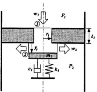
1) 1. 서 론 가정에서 쓰이는 냉장고, 에어컨에 들어가는 압 축기는 냉매의 보충이 필요하지 않게 밀폐된 용기로 제작이 된다. 이에 따라 보수가 불가능하기 때문에 내부 부품의 내구성을 생각하지 않을 수 없다. 또한 소비자의 소음진동에 대한 만족기준이 점점 올라감 에 따라 소음원에 대한 생각도 해야 한다. 압축기가 가동될 때, shaft의 거동을 예측 할 수 있다면, 이를 조절해서 부품의 내구성을 올리고, 소 음원은 줄일 수 있을 것이다. 여기서는 탄성체 shaft 를 모델링 하고, 가진력을 규명하여, 탄성체 shaft의 운동방정식을 세워 거동을 예측 하고자 한다. † 교신저자; 정회원, 부산대학교 기계공학부 E-mail : [email protected] Tel : 051-510-3088 , Fax : 051-517-3805 ‡ 발표자; 부산대학교 기계공학부 2. 피스톤에 의한 힘 2.1 밸브 압축기의 흡입밸브는 fig.1처럼 1자유도로 모델 링 할 수 있다.1) 이때 흡입밸브의 운동방정식은 다 음과 같다. (1) 여기서 은 흡입압력 또는 토출 압력이고, 는 실린더 내부 압력이다. 밸브를 통해 들어오는 냉 매는 유선에 따른 비정상(unsteady) 무마찰 유체흐 름이고, 이에 대한 베르누이 방정식은 다음과 같다. (2) 한국소음진동공학회 2014년 추계학술대회 768
Figure 1 Modeling of suction port 여기서 는 유체의 유동속도이고 식 (3)의 형태로 나타난다. (3) 또한, 는 유체의 밀도이고, 식 (4)과 같다.
(4) 유체의 상승을 무시하면 유체의 유동속도 식을 에 대입하서 흡입밸브에서 압력과 유속에 대한 지배 방정식을 다음과 같이 얻을 수 있다. ln ln (5) 토출밸브도 동일한 과정을 통해 토출밸브의 변 위 와 토출유속 도 구할 수 있다. 2.2 실린더 내부 압력 흡입밸브와 토출밸브에서 냉매의 유속을 구했기 때문에 실린더 내부의 냉매질량의 변화량을 구할 수Figure 2 shaft and journal bearing
있다. (6) 이를 이용해서 실린더 내부 압력을 다음 식을 통 해 계산 할 수 있다. (7) 3. 저널베어링 Shaft에 변위가 생겼을 때 저널베어링에서 비선 형적인 반력이 발생하게 된다. 이를 구하기 위해 유 막에 대한 Reynolds 방정식을 사용하였다.2) Reynolds 방정식은 다음과 같다. (8) 여기서 유막두께 는 다음과 같다. cos sin (9) 이를 통해 경계조건을 고려해서 정리하면 베어링 의 반력은 다음과 같다. 769
0 50 100 150 200 250 300 350 -70 -60 -50 -40 -30 -20 -10 0 10 20 Crank-shaft angle(deg) F (N ) x-direction y-direction
Figure 3 Reaction force of bearing
(10) 단, 압력 는 다음과 같이 표현 된다. cos sinsin cos cos sin
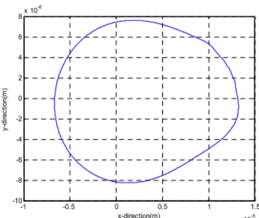
(11) 여기서 는 복소수 이고, 실수부는 방향, 허수 부는 방향의 성분이다. 여기서 는 각속도 는 베어링 부 shaft의 반지름, 는 베어링 길이, 는 유체의 점성계수 이다. 4. 수치해석 실린더 내부압력을 구하는 데에는 FDM을 사용 하였고, shaft의 변위를 구하는 데에는 유한요소법을 이용해 운동방정식을 세우고 모드좌표계를 이용해서 Runge-kutta로 해석을 수행했다. 압축기 가동 중 베어링의 반력을 fig.3과 같이 계 산할 수 있었다. 그리고 이를 통해 shaft의 변위를 fig.4에서 보이는 것처럼 예측해 볼 수 있었다. 5. 결 론 이론적으로 실린더의 내압과 베어링 반력을 모델 링 하여 shaft의 동적 거동이 예측 가능하다는 것을 알 수 있었다. 만약 실험 데이터를 통해 실제 압축 -1 -0.5 0 0.5 1 1.5 x 10⁻⁵ -10 -8 -6 -4 -2 0 2 4 6 8x 10 -6 x-direction(m) y -d ir e c ti o n (m )
Figure 4 The trace of the shaft
기의 거동 조건과 비교하여 여러 가지 물성치들을 수정한다면, 실제 shaft의 거동을 충분히 예측 가능 할 것이다. 그렇다면, 이를 통해 shaft의 설계를 변 경하여 내구성 문제와 소음의 문제를 줄이고자 할 때 많은 도움이 될 것이다. 참 고 문 헌
1) Moon, S. J, Cho, J. R. and Kim, H. O. 2003, Finite Element Analysis of Piston Slap Phenomenon in Reciprocating Compressors Considering Coolant Circulation, The Korean Society of Mechanical Engineers No.27 pp. 1087~1094.
2) Kim, T. J, 2001, Dynamic Behavior Analysis of a Crankshaft-Bearing System in Variable Speed Reciprocating Compressor, Journal of the KSTLE Vol. 17, No 6, pp. 426~434