1. INTRODUCTION
Hydraulic excavator have been popular device in construction field because of its multi-working and economic efficiency. The application of this complex device will be extended manufacture, agriculture, undersea etc.
But its operating need very difficult skill because operator has to operate joysticks and pedals consequently. So accuracy of work is influenced by operator’s skill. But environment of work is poor and difficult skill bring about feeling fatigued fast. Autonomous excavator can be a kink of solution about previous problems and many researches have been achieved by many researchers. British Columbia university in Canada, Carnegie Mellon university in USA and Sydney university in Australia have field robot center and have made a special studies with excavator and many construction equipment makes have prototype or autonomous excavator in part.
The paper map in field robot with excavator made before in my laboratory show that 56 % of papers focus in modeling of attachment (Boom, Arm, Bucket) using Lagrange Euler equation and applying control algorithms but hydraulic circuit and valves are modeled very simply. For example, main control valves having nonlinear open area characteristics are modeled in simple variable orifice and logic valves are omitted. In many paper, researchers use robust controller in order to overcome nonlinearities created by complex open area characteristics and dead zone of valve, single acting cylinder, heavy weight of attachment. Because of many nonlinearities, experiments are positively necessary but limited by time, money, place etc.
The objective of this paper is to develop a simulator for hydraulic excavator using AMESim. Components and whole circuit are expressed graphically. Parameters and nonlinear characteristics are inputted in text style. The simulator can be used to forecast excavator behavior when new components, new mechanical attachments, hydraulic circuit changes, and new control algorithm are applied. The simulator could be a kind of development platform for various new excavators.
2. ATTACHMENT MODEL
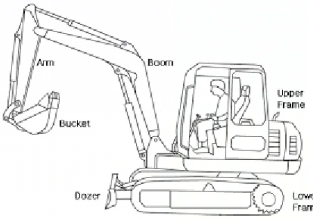
Hydraulic excavator consist of upper frame, lower frame and attachment. Upper frame contain operating room, engine, pump, main control valve (MCV) and attachment is fixed to end of upper frame. Lower frame contain crawler or wheels and upper frame can rotate by swing motor. In this paper, attachment is modeled boom, arm, bucket except swing and drive and excavator model is 5 ton of Hyundai Heavy Industry.
Fig. 1 The A hydraulic excavator
2.1 Attachment model
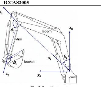
Fig. 2 shows the coordinate systems of excavator and motion equation was established by Lagrange equation.
∑
∑
∑
= = ==
=
+
+
n k i i k j ijk n j j n j ijq
h
q
q
G
Q
i
n
H
1 1 1,...,
1
,
&
&
&&
(1) j ijq
H
&&
is inertia torque including interaction torque by offdiagonal element of attachment inertia tensors,
h
ijkq
&
jq
&
k is Coriolis and centrifugal effects andG
i is gravity torque.Simulator for Hydraulic Excavator
Tae-Hyeong Lim*, Hong-Seon Lee
**and Soon-Yong Yang
**** Department of Mechanical and Automotive Engineering, University of Ulsan,Ulsan, Korea (Tel : +82-52-259-2731; E-mail: [email protected])
**Department of Construction Equipment, Hyundai Heavy Industry, Ulsan, Korea (Tel : +82-52-230-8988; E-mail: [email protected])
***School of Mechanical and Automotive Engineering, University of Ulsan, Ulsan, Korea (Tel : +82-52-259-2820; E-mail: [email protected])
Abstract: Hydraulic excavators have been popular devices in construction field because of its multi-workings and economic efficiency. The mathematical models of excavators have many nonlinearities because of nonlinear opening characteristics and dead zone of main control valve, oil temperature variation, etc. The objective of this paper is to develop a simulator for hydraulic excavator using AMESim. Components and whole circuit are expressed graphically. Parameters and nonlinear characteristics are inputted in text style. The simulator can be used to forecast excavator behavior when new components, new mechanical attachments, hydraulic circuit changes, and new control algorithm are applied. The simulator could be a kind of development platform for various new excavators.
.
Fig. 2 Coordinates system
Fig. 3 present AMESim model of attachment. The supercomponent of attachment is shown right and upper part in fig. 3 and this contain the rest components. Each component contain link’s characteristic-length, mass, inertia etc. The coordinates in fig. 2 are contained the attachment super- component. The inputs of supercomponent are force of cylinder and outputs are angular displacement of boom, arm and bucket.
Fig. 3 AMESim model of attachment
3. HYDAULIC CIRCUIT MODEL
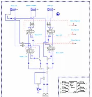
Main pump operated by engine make two type of pressures that main pressure work each cylinder and pilot pressure work spool of main control valve by operating joystick. If operator handle joystick or lever, pilot pressure push the spool of MCV, the rate and direction of flow is decided by spool displacement and direction and flow rate can decide of direction and velocity of cylinder. Working area is assumed 2D in this paper, hydraulic circuit can be simplified like fig. 4. Because boom up and arm dump need much flow rate, join of flow rate between boom 1 valve and boom 2 valve, arm 1 valve and arm 2 valve.
Fig. 4 Hydraulic circuit of excavator
3.1 Joystick
The role of joystick is supplying pilot pressure to MCV by operate angle. The AMESim model of joystick is shown in fig. 5. components in dotted square are contained supercomponent in left hand side. Operating of joystick is assumed to signal between -1 to 1 and pilot pressure to A, B port is directly proportional to signal. The input signal to joystick model is fig. 6 (a) and pilot pressure at port A, B is (b). In fig., pilot pressure response is proportional and delay is rare.
Fig. 5 AMESim model of joystick
(a) Input signal
(b) Pilot pressure at A, B port Fig. 6 Result of joystick model
3
3.2 Pump
The pump assembly consist of 2 variable pump for main pressure and 1 fixed pump for pilot pressure. Variable pump has control algorithm for energy saving, this can be cha- racterized to P-Q diagram. The AMESim model of pump assembly is shown in fig. 7. Various P-Q diagram can be tested in this model easily because P-Q diagram is inserted by text file. For verification of pump model, input and output P-Q characteristics are shown in fig. 8. The solid line is input and dotted line is output. This pump model is verified with valve and cylinder.
Fig. 7 AMESim model of pump
P-Q 0.00 10.00 20.00 30.00 40.00 50.00 60.00 0.00 50.00 100.00 150.00 200.00 P [kg/cm^2] Q [ L /m ^3
AMESim Result Original
Fig. 8 Result of pump model
3.3 Boom 1 valve
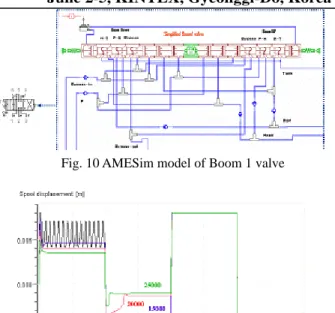
Boom 1 valve, decide direction and velocity of boom cylinder mainly, is modeled 6 port 3 position valve. The spool displacement-Open area diagrams contain many nonlinearities dead zone, saturation and unproportional characteristic. These nonlinear diagrams are put into model text file. Fig. 9 show open area diagrams. The velocity of boom cylinder at up and down will be different because of nonsymmetrical diagram. Fig. 10 is AMESim model of boom 1 valve. The components in dotted square are packed into super- component in left hand side in fig. Fig. 11 show that spool displacement in various spring stiffness. 0 10 20 30 40 50 60 70 80 -0.008 -0.006 -0.004 -0.002 0.000 0.002 0.004 0.006 0.008 PH RT PR HT PH-data RT-data HT-data PR-data
Fig. 9 Open area diagram of boom 1 valve
Fig. 10 AMESim model of Boom 1 valve
Fig. 11 Spool displacement in variable stiffness Stiffness variation has influence upon valve displacement. Too low stiffness produce oscillation of spool and errors between up and down are different to each other. 17000 make the error to minimum and spool displacement is shown in fig. 12. The displacement error at boom up is 0.316[mm], at boom down is 0.61[mm].
Fig. 12 Spool displacement at stiffness 17000 [ ]
2
m N
3.4 Boom 2 valve
The role of boom 2 valve is supply flow rate to boom cylinder at boom up. The boom 2 valve model has same structure with boom 1 valve model and different open area diagram. 20000 make the error to minimum and spool displacement is shown in fig. 13. The displacement error at boom up is 1.02[mm]
3.5 Arm 1 valve
Arm 1 valve, decide direction and velocity of Arm cylinder mainly, has same structure with boom 1 valve model and different open area diagram. 20000 make the error to minimum. The displacement error at arm dump is 0.0534[mm], at arm crowd is 0.284[mm].
3.6 Bucket valve
The final spring stiffness of bucket valve is 26000 and error at bucket dump is 0.042[mm], at bucket crowd is 3.17[mm].
Fig. 13 Spool displacement in variable stiffness
Fig. 14 Spool displacement at stiffness 20000 [ ]
2
m N
3.7 Main Control Valve (MCV)
The main control valve block consist of previous hydraulic components(3.1~3.6) is shown in fig. 15. The working fluid through by pass go to tank and feature of circuit is similar to simpliflied circuit in fig. 4. The port relief is added to cylinder in, out port.
Fig. 15 AMESim model of MCV
4. TOTAL MODEL & SIMULATION
Total excavator model is constructed in fig. 16 using previous models.
Fig. 16 AMESim model of excavator
Though stiffness tuning was done, results at complex motion is different from it at single motion. Simulation condition is that operate joystick 50 [%] to + for 4 [sec] , 50 [%] to -, 100 [%] to + and 100 [%] to – of boom, arm and bucket simultaneously. Fig. 17 show spool displacement of boom 1 valve and boom 2 valve under simulation condition. Displacement error is bigger than simple motion that is because pressure at cylinder effect to MCV. Fig. 18 show angular displacement of attachment and pressures at boom cylinder are shown in fig. 19.
Fig. 17 Spool displacement of boom valves at complex work
5
Fig. 19 Pressures of boom cylinder5. CONCLUSION & FUTURE WORK
Each component of attachment and hydraulic circuit of excavator and total excavator is modeled with AMESim.To find constant spring stiffness make error to minimize tuning has done each valve model and result is as follow.
For boom 1 valve error at boom up is 0.316[mm], boom down is 0.61[mm] with stiffness 17000. In case of boom 2 valve, error at boom up is 1.02 [mm] with stiffness 20000. Arm 1 valve, error at arm dump is 0.0534, arm crowd is 0.284 [mm] with stiffness 20000. In bucket valve, error at bucket dump is 0.042[mm], at bucket crowd is 3.17[mm] with stiffness 26000. So, constant spring stiffness can’t satisfy accuracy of spool displacement for all condition. In order to proportional to displacement of MCV it is need to construct closed loop type MCV.
The AMESim model for total excavator will be used to verify new control algorithm or new component. Under being many limit to make an experiment with real excavator, this AMESim model will play an active part in simulator or test bench.
ACKNOWLEDGMENTS
This work was supported by the Korea Science and Engineering Foundation (KOSEF) through the research center for machine parts and material processing at University of Ulsan and Hyundai Heavy Industry.
REFERENCES
[1] T. R. Kane, "Dynamics : Theory and Applications", McGraw-Hill, 1985.
[2] R. P. Paul, "Robot manipultors : Mathematics, Programming, and Control", The MIT Press, 1981. [3] J. Watton, “Fluid Power Systems, Prentice Hall, 1989. [4] “AMESim User's Manual”, IMAGINE, 2000. [5] S. Y. Yang etc. "A Study on Trajectory Tracking Control