Design Features of a Core Protection System for an Integral Reactor
Bon-Seung Koo, Wang-Kee In, Keung-Koo Kim, Chung-Chan Lee, Sung-Quun Zee Korea Atomic Energy Research Institute, 150 Deokjin-dong, Yuseong-gu,Daejon, 305-353, Korea1. Introduction
A system-integrated modular advanced research reactor is under development in the KAERI. Therefore, it is required to design an advanced core protection system for an integral reactor and an online digital core protection system, SCOPS[1] is being developed as a part of plant protection system. SCOPS calculates the minimum CHFR(Critical Heat Flux Ratio) and maximum LPD(Local Power Density) based on the several online measured system parameters, such as the excore detector signal, CEA positions, MCP pump speed, pressure and temperature. Calculated values are compared with predetermined limiting values and the trip signal is generated if necessary.
This paper describes the basic design features of SCOPS and several output parameters for a simple test case are presented.
2. SCOPS Design Basis
The low CHFR and high LPD trips of SCOPS assure that the Specified Acceptance Fuel Design Limits (SAFDL) for a boiling crisis and centerline fuel melting are not exceeded during anticipated operational occurrences. Also, SCOPS shall meet additional design bases via auxiliary trip functions and these auxiliary trip functions can aid in meeting the primary design bases.
- Range trip and core exit saturation trip. - Internal processor failure trip and so on.
3. System Requirements 3.1 Inputs and Outputs
Table 1 and Figure 1 show the SCOPS process input signals for each channel. Four RSPTs per CEA are directly used in SCOPS to establish the 2-out of-4 trip logic. Digital type measurable system parameters should be proportional to the value of the respective measured process variable.
Two trip outputs are required to be input to the plant protection system for use as CHFR and LPD trip signals. The CEA Withdrawal Prohibit (CWP) signal within the plant protection system shall be initiated by the CHFR or LPD pretrip or CEA deviation condition or out-of-sequence condition of the CEA group. In addition, the CHFR and LPD margin, neutron flux power, calibrated coolant flow rate are required to be monitored by an operator.
Table 1. SCOPS process input signals. Sensor
Signal
No. per
Channel Range Unit
Signal Type MC 2 10-100 % speed Digital TC 1 250-350 ℃ Digital TH 2 250-350 ℃ Digital Pr 1 11-17 MPa Digital Di 3 0-200 % Digital
CEAi 12 0-100 % withdrawal Digital
Figure 1. SCOPS input signal configuration.
3.2 Program Structure
The SCOPS design bases requires that the system calculates conservatively but relatively accurate values of CHFR and peak local power density (PLPD). However the algorithms which require sufficiently detailed calculations cannot be executed rapidly enough to provide a protection for those design basis events with the most rapid approach to the SAFDL. In order to achieve a system time response sufficient to accommodate the limiting design basis events, additional dynamic calculations of CHFR and PLPD are required. The dynamic calculations must provide conservative estimates of the CHFR and PLPD based on the changes in the process variables between successive detailed calculations. The detailed calculations of the CHFR and PLPD must be separated into different programs.
The resultant protection program consists of five interdependent modules and one subroutine, which is accessible by the first two modules:
1) Reactor coolant mass flow module (COOLANT) 2) CHFR & power density update module (CHECK)
Transactions of the Korean Nuclear Society Autumn Meeting Busan, Korea, October 27-28, 2005
3) Power distribution module (POWER) 4) Static CHFR calculation module (THERM) 5) CEA position module (CRPOS)
6) Trip sequence subroutine (TRIP)
Figure 2 shows the interfaces between the SCOPS program. The functional algorithms of each module are as follows:
COOLANT module computes a normalized flow rate of the primary coolant system and an adjusted value of the CHFR based on the number of MCP running.
CHECK module computes an updated value of the CHFR, quality margin and local power density based on temperature, pressure, core power and power distribution. Also the neutron flux power, thermal power, hot pin axial offset, hot pin heat flux, one-pin integrated radial peaking factor are computed.
POWER module computes the core average axial power distribution, pseudo hot pin power distribution and the three dimensional power peaking from the excore detector signals and CEA group positions.
THERM module computes the static values of the CHFR, hot channel quality and the maximum core exit temperature. In addition, this module establishes the static values of the process variables which are used in the CHFR update.
CRPOS module computes the CEA position and CHFR and LPD penalty factors. CRPOS module receives all of the individual CEA positions from the RSPT type position sensor and calculates the representative group positions and two penalty factors based on the CEA deviation within a subgroup. These group positions and two penalty factors are transmitted to the POWER and CHECK module, respectively.
In TRIP, the minimum CHFR, quality margin and peak LPD are compared with their predetermined setpoints. Whenever a setpoint is violated, the appropriate trip output transfers to the plant protection system. In addition, trips shall be initiated for core conditions outside the analyzed operating range.
Figure 2. Interface between SCOPS program.
3.3 Program Timing and Input Sampling Rates
Execution of the five modules shown in Figure 2 shall be scheduled on a priority basis. The execution
frequency of each protection module shall be fixed, based on the required SCOPS time response. In addition, the more frequently executed modules shall be assigned a higher priority. The TRIP sequence shall be called by the COOLANT and CHECK modules. Sampling of the input signals shall be initiated within the protection programs. Therefore the sampling rate for a given input is the same as the execution frequency of the module that reads that input parameter.
4. Test Results and Conclusion
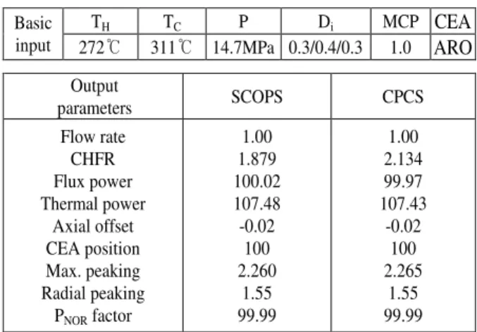
A simple test was performed to see if SCOPS could calculate major output parameters correctly and the parameters were compared with those of CPCS[2,3], which is a reactor protection system for C-E type plants. In the test, some database inputs for SCOPS are artificially modified to generate the same primary system parameters, such as the temperature, pressure, excore detector, MCP speed, Shape Annealing Matrix and so on. Table 2 shows that the test results and major output parameters of SCOPS agree with the results of CPCS.
Therefore, it seems that SCOPS has a basic calculation ability as a core protection program but database analysis and improvement of detailed algorithms to simulate the integral reactor more correctly are needed as a future work.
Table 2. Major output parameters of SCOPS and CPCS.
TH TC P Di MCP CEA
Basic
input 272℃ 311℃ 14.7MPa 0.3/0.4/0.3 1.0 ARO
Output parameters SCOPS CPCS Flow rate CHFR Flux power Thermal power Axial offset CEA position Max. peaking Radial peaking PNOR factor 1.00 1.879 100.02 107.48 -0.02 100 2.260 1.55 99.99 1.00 2.134 99.97 107.43 -0.02 100 2.265 1.55 99.99 Acknowledgement
This research has been performed under the nuclear R&D program supported by the Ministry of Science and Technology of Korean Government.
REFERENCES
[1] K. K. Kim et al., Development of a SMART Core Protection System Code, KAERI/TR-2018, 2002.
[2] Functional Design Requirements for a Core Protection Calculator, Rev. 02-P, Combustion Engineering Inc., 1988. [3] Functional Design Requirements for a Control Element Assembly Calculator, Rev. 01-P, Combustion Engineering Inc., 1988.