Research Article
Time Domain Equalization and Digital Back-Propagation
Method-Based Receiver for Fiber Optic Communication Systems
Fazal Muhammad ,
1Farman Ali ,
2Usman Habib ,
3Muhammad Usman,
4Imran Khan ,
4and Sunghwan Kim
51Department of Electrical Engineering, City University of Science and Information Technology, Peshawar 25000, Pakistan 2Electrical Engineering Department, Qurtuba University of Science and Information and Technology, Dera Ismail Khan 29190,
KP, Pakistan
3School of Electrical Engineering, Korea Advanced Institute of Science and Technology, Daejeon 34141, Republic of Korea 4Electrical Engineering Department, University of Engineering Technology, Mardan 23200, KP, Pakistan
5School of Electrical Engineering, University of Ulsan, Ulsan 44610, Republic of Korea
Correspondence should be addressed to Sunghwan Kim; [email protected]
Received 23 November 2019; Revised 9 January 2020; Accepted 13 January 2020; Published 12 February 2020 Academic Editor: Wonho Jhe
Copyright © 2020 Fazal Muhammad et al. This is an open access article distributed under the Creative Commons Attribution License, which permits unrestricted use, distribution, and reproduction in any medium, provided the original work is properly cited.
Fiber optic communication systems (FOCSs) have attained a lot of attention by revolutionizing the telecommunication industry and offering new possibilities with the technical advancements in state-of-the-art high speed digital electronics. Advanced modulation formats make use of the phase, amplitude, and polarization of the optical signals at the same time to provide high spectral efficiency as compared with 1 bit/s/Hz for the intensity modulation direct detection system (IMDD), but are highly prone to transmission impairments. Thus, the effects that add up to the optical fiber impairments such as optical fiber chromatic dispersion (OFCD), polarization model dispersion (PMD), and phase offset and noise (POaN) need to be addressed at the receiver side. The development of components and algorithms to minimize these effects in next generation FOCSs with 100 Gbps data rate and beyond with long-haul transmission is still a challenging issue. In this paper, digital signal processing- (DSP-) assisted dispersion and nonlinear compensation techniques are presented to compensate for physical layer impairments including OFCD, PMD, and POaN. The simulations are performed considering Dual Polarization- (DP-) QPSK modulation format to achieve two-fold data rate to achieve spectral efficiency of 3.28 bits/s/Hz by making use of the polarization diversity and system performance is investigated in terms of bit error rate (BER), constellation diagrams, and quality factor (Q-factor) for different values of optical signal-to-noise ratio (OSNR), launch power (PL), and fiber length.
1. Introduction
The introduction of telegraphy in 1830s [1] led to the de-velopment and design of many further telecommunication technologies. The increased demand for bandwidth and low-cost transmission over long distances led to the use of the optical waves by 1970s, to achieve ultralarge capacity and use optical fiber as the transmission medium [2]. The ad-vancement of fiber optic communication system (FOCS) is spread over various generations, which was boosted by the advent of Erbium-doped fiber amplifier (EDFA) in the 1980s
because it enabled long-haul transmission [3]. The optical amplification enabled increase in repeater spacing and wavelength division multiplexing (WDM), which resulted in ultrahigh bit rates [4] and making the FOCSs a primary mean of information transportation on a global scale. The ultimate goal of a FOCS is to provide high throughput through the desired transmission range, which requires careful design considerations for the system configuration, generally consists of a transmitter (Tx), optical fiber as the channel, and a receiver (Rx). Optical fiber is utilized in FOCS applications in two basic forms, from short range which use Volume 2020, Article ID 3146374, 13 pages
multi mode fiber (MMF) [5] to long-haul links employing single mode fiber (SMF) [6]. To achieve high spectral effi-ciency (SE), which mainly represents the maximum theo-retical data throughput of a system and how efficiently the total available bandwidth is being used, high order modu-lation formats can be used according to the available optical signal-to-noise ratio (OSNR). In a multichannel transmis-sion system, such as wavelength divitransmis-sion multiplexing (WDM) with constant transmit power, the maximum achievable SE is an increasing function of the channel quantity and OSNR [7]. To cope with the demand of multi-Gb/s of data rates, the channel impairments such as optical fiber chromatic dispersion (OFCD), polarization mode dispersion (PMD), and phase offset and noise (POaN) in the FOCS need to be treated. These effects are major bottleneck for ultrahigh data rate systems such as 40 Gbps and 100 Gbps capacity Passive Optical Networks (PONs) which are gen-erally supported by wavelength division multiplexing (WDM) and are operated for distances under 100 km [8]. The situation is even worse for long-haul transmission, even deploying the coherent detection scheme [9, 10], because of cumulative dispersion and multiple bends throughout the optical fiber link.
In this paper, the transmission impairments are addressed in a Dense-WDM (DWDM) FOCS using con-ventional digital signal processing techniques [11] with a phase dithering technique and a modified version of the digital back-propagation method. We focus on long-haul FOCS, using optical amplification with EDFA to compensate the optical losses and RF amplification at the receiver end for optical to electrical conversion loss. The simulations are performed by varying the system parameters such as, length of the fiber, input optical power, and modulation scheme to quantify the performance in terms of OSNR, bit error rate (BER), and quality factor (Q-factor). Moreover, a constel-lation analyzer is used to show the performance of
quad-rature modulation schemes before and after the
implementation of DSP compensation techniques. C-band [12] with wavelength, λ, ranging from 1528.77 nm to 1568.36 nm is used for simulation work for realization of commercially used equipment in a FOCS.
1.1. Related Work. For modulation schemes utilizing both
amplitude and phase of the optical carrier, such as QPSK, the accumulated effects [13] pose a challenging situation at the receiver end. Recent work on a QPSK-based system [14] on mitigation of the channel effect shows the extend to what chromatic dispersion and polarization mode dispersion can degrade the performance. Even for coherent detection-based systems where advanced modulation formats are used [15], DSP assistance is required to achieve acceptable value of BER. As dispersion also causes power loss for the system, DSP techniques which provide power efficiency [16] can enable high data rates for such cases. DP-QPSK has been shown to provide high data rates with the use of dispersion compensation fiber and DSP techniques [17]. DSP tech-niques are a powerful tool to compensate optical fiber transmission impairments in single carrier systems as shown
by many researchers to achieve high capacity and error-free transmission. In [18], a frequency domain equalizer has been suggested for FOCS to minimize PMD losses. Some re-searchers [19] have shown an analysis of coupling behaviors for two linear polarized modes using DSP up to 10 km transmission range. A demonstration of higher order modulation format data transmission with Raman amplifiers is performed with DSP techniques in [20]. In [21], authors have discussed a 4-channel FOCS over 26 km SMF in terms of DSP and digital filters, but the implementation cost of such filters is a real issue. Similarly, in [22], researchers used methodologies such as coherent optical orthogonal fre-quency multiplexing (COOFDM) for FOCS, where they successfully addressed the nonlinear issues, but the trans-mission distance for an order of 100 km still needs to be investigated to analyze the cumulative channel effects for long-haul FOCS. In this work, we focus on OFCD, PMD, and POaN impairments for long-haul transmission dis-tances using time domain equalization, as compared with frequency domain, to support commercially used standards using TDM. The use of DP-QPSK modulation format for high data rate and DSP-assisted receiver with the digital back-propagation method to compensate nonlinear fiber effects has been shown in this work.
1.2. Major Contributions. Transmission over longer
dis-tances using ultrahigh data rate systems is mainly carried out using repeaters within the transmission spans. For a het-erogeneous network or multi-Radio Access Technology (multi-RAT), the current optical fiber transmission tech-niques such as ethernet-over-fiber or digital-over-fiber re-quire an adaptive set of repeaters to support multiple standards. Large number of such repeaters will be a costly solution, and the requirement of regular maintenance and checks is also an issue. Moreover, the additional noise in the regeneration or amplification steps will further deteriorate the performance. The trade-off exists between the use of high data rates which are mainly limited due to OFCD, PMD, and POaN impairments for very long distances and overall deployment cost of the complete FOCS. In this work, the process of adaptive equalization through advanced DSP and use of Gaussian filters with the digital back-propagation technique to minimize PMD, OFCD, and POaN have only been used at the receiver end to provide a cost-effective solution. As the digital back-propagation technique has been used in the previous work for mitigation of deterministic non-linear effects, a modified version is presented in this work with an adaptive equalizer to provide assistance against the randomly distributed PMD effect. Similarly, the phase dithering technique has been introduced at the transmitter end to assist the DSP receiver for mitigation of OFCD. The main handouts of this paper are listed as follows:
(1) Channel impairments like OFCD, PMD, and POaN are investigated for long-haul FOCS transmission, to quantify the capacity and transmission range. (2) A simple low-complexity receiver design for the
offline processing in MATLAB after the termination of transmission.
(3) Simulation results are performed-based on mathe-matical model of the proposed set up. Optisystem simulation software is used to conduct simulation work, and results are obtained by varying inde-pendent variables such as length of fiber and input optical power to achieve performance parameters such as Q-factor, BER, and OSNR.
(4) The simulation results of the designed FOCS are compared with the use of conventional signal de-tection schemes at the receiver as compared with the time domain equalization, DSP assistance, and digital back-propagation technique. The results de-clare that the proposed framework mitigates the effects of OFCD, PMD, and POaN impairments and proves to be several times efficient than the current FOCS.
(5) To provide high SE, an advance modulation DP-QPSK method is implemented at the transmitter side of the proposed FOCS to provide polarization di-versity along with the phase didi-versity.
1.3. Organization and Notation of Paper. The remaining
portions of this paper are arranged as follows. Section 2 discusses the framework of the proposed model and Section 3 consists of the analytical model with mathematical model representation. Section 4 includes results and discussion of the proposed model. Conclusions from the presented work are in Section 5. Table 1 presented the notations used in the paper, for the convenience of the readers.
2. Framework of the Proposed Model
In Section 1, the background of FOCS and literature review are presented. Moreover, as the FOCS acts as the backbone of the current communication networks, the optimization of the FOCS framework is necessary against channel impair-ments such as OFCD, PMD, and POaN. Figure 1 shows the block diagram of the proposed system. The system model is composed of various components, and the parametric values of the components are varied to optimize the performance of the overall system. The data are transmitted through a continuous wave (CW) laser which modulates the user data. A pseudorandom binary sequence (PRBS) generator is used to generate data, followed by a DP-QPSK modulator and a RF amplifier to adjust the gain. The laser beam is split into two polarization orientations using a Polarization Beam Splitter (PBS). A set of identical Mach–Zehnder Modulators (MZMs) is used to modulate the two optical carriers from the PBS, which are afterwards combined and transmitted through 500 km length of SMF. To compensate the fiber attenuation, an erbium-doped fiber amplifier (EDFA) [23] is installed after each 100 km of fiber range. After transmission over optical fiber, the transmitted optical signals are reconverted to electrical form using a DP-QPSK receiver which consists of a Laser LO for coherent detection, a PBS, a 90 degree optical hybrid to mix the signals, and four
photodiodes for balanced photodetection. Then, the resulting electrical signals are proceeded to a low pass RF filter, electrical amplifier, and a DSP unit to recover the data from the OFCD, PMD, and POaN effects. Threshold de-tection and parallel to serial converter are utilized by the BER test set to analyze the performance of the system at the Rx side.
The conventional receiver for the coherent detection scheme performs DC blocking, compensation of In-phase Quadrature (IQ) imbalance, timing recovery, and fre-quency/phase offset compensation. The effect of high amplitude DC component on the data transmission is thus removed, and the signal is compensated for the IQ im-balance effects which are caused due to the imperfection between the amplitude and phase of I and Q components. The symbols are synchronized using timing recovery which mainly estimates the sampling frequency and phase. Fre-quency and phase offset between the received signal and the local oscillator at the receiver are common problems in coherent systems, which can be compensated by utilizing pilot tones or preamble frames as a training sequence. The proposed receiver uses DSP block from the Opitsystem, and two additional DSP steps are performed using MATLAB script. The first one is the use of the phase dithering technique with a digital filter to reduce the nonlinear distortion effects by introducing a dithering signal at a high RF frequency, so that the noise shape in the frequency domain changes to shift high noise level towards the higher frequencies. The second step is the use of the digital back-propagation technique to further improve the performance of the system against cumulative chromatic dispersion, which will be explained later in mathematical model of the proposed system. Also, an adaptive polari-zation controller has been used to estimate the mismatch between the two polarization modes of the received signal and to perform its correction.
2.1. Optical Fiber Channel Impairments. In this paper,
OFCD, PMD, and POaN impairments are analyzed and mitigated for the proposed FOCS model. The effect of these impairments in a long-haul FOCS are explained as follows. Table 1: Notations and their descriptions used for the proposed model.
Description Notation
Wavelength λ
Attenuation of the fiber α
Transmitter Tx
Receiver Rx
Phase offset θ△
Signal amplitude ζs(t)
Signal carrier frequency ψt
Responsivity κ Stokes parameter τ Fiber attenuation α Dispersion slope Ψ Speed of light c Intensity of noise ξIN
2.1.1. Optical Fiber Chromatic Dispersion. Broadening of the
optical signals happens due to the OFCD, as light pulse travels in SMF at several speeds due to multiple factors [24]. The transmission quality, and hence the data rate, is reduced due to this critical factor as shown in Figure 2. Thus, this effect needs to be treated for higher transmission speeds. In our proposed model, we compensate the OFCD by using digital filters in the time domain, due to its several ad-vantages over the frequency domain implementation [25] for improved selection of data signals. With the help of these procedures, the proposed framework performs better in terms of BER, OSNR, and Q-factor.
2.1.2. Polarization Mode Dispersion. Use of polarization
diversity doubles the transmission rate as different data can be sent over the two propagation modes of light, which travel together inside the fiber. But, this technique is mainly af-fected by the PMD. The two modes of light are supposed to propagate with same velocity inside SMF, but this is not the case in practical systems. A small birefringence is generated when the light source is encountered inside the fiber [26]. This phenomenon becomes valuable in case of high speed transmissions utilizing polarization diversity. As a result, delay shift occurs among transmitted modes as mentioned in Figure 3. Just like OFCD, the PMD distorts the optical pulse inside SMF and thus limits the transmission rates in long-haul FOCS. Thus, to enable long-long-haul and high-speed FOCS, mitigating measures have to be adopted.
2.1.3. Phase Offset and Noise. The FOCS performance is
impaired by another key limiting factor known as POaN. It happens when several wavelengths travel over an SMF with same phase angle but reaches at the other end with a phase offset [27] due to the reflections and refraction from core and cladding. As a result, the transmitted optical pulses face phase offset and related phase noise [28].
2.2. DP-QPSK Compared with Other Modulation Formats.
Amplitude phase shift keying (ASK) also known as on off keying (OOK) [29] is a well-known modulation scheme in FOCS due to its simplicity but is less efficient in terms of power and is very susceptible to noise interference. OOK is a digital modulation technique in which analog carrier is modulated by a digital signal. The intensity of the carrier
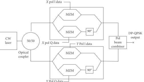
light is varied to represent binary data inputs, while fre-quency and phase of the carrier signal remain constant. The other mostly used modulation formats are frequency shift keying (FSK) and phase shift keying (PSK), which modulate the frequency and phase of the carrier with respect to the input binary data signal, respectively [30]. The FSK mod-ulation technique uses two different carrier frequencies to represent binary 1 and binary 0, and thus uses larger bandwidth compared with other modulation techniques. PSK is a digital modulation technique which changes phase of the analog carrier to represent digital binary data [31]. In a two-level PSK scheme, a difference of 180 phase shift is used between binary 1 and binary 0. Another modulation format called Differential PSK (DPSK) provides better performance than the rest, in which the information is encoded in the phase between two successive bits. Quadrature PSK is a form of advanced modulation formats in which the data infor-mation modulates both amplitude and phase of the signal, thus providing improved energy efficiency and SE. Hence, the DP-QPSK is proposed to be used in this work to increase the data rate by making use of the polarization diversity, along with the QPSK modulation format. The block diagram of DP-QPSK is shown in Figure 4 which consists of a po-larization beam splitter, and two different QPSK data streams are modulated over the X and Y polarized optical carrier signals.
2.3. Proposed Digital Signal Processing Unit. The phase
locking, OFCD treatment, and polarization adjustment are the main challenges in the traditional FOCSs using advanced modulation schemes which are addressed in the proposed DSP unit whose framework is shown in Figure 5. In addition, the phase dithering technique is applied at the transmitter end for noise shaping and to reduce the effects of nonlinear distortions. In FOCS, the electrical signals output from the photodetector are transformed into discrete signals using analogue to digital converters (ADCs), to be processed by the DSP unit [32]. The DSP module also provides time domain equalization for channel impairments and is able to detect DP-QPSK with superior receiver sensitivity and time recovery. This section summarizes the proposed framework, physical impairments, SE, and the techniques used for mitigating channel effects and DSP steps. The following Section 3 involves an analytical approach for the proposed model. DP-QPSK Tx DP-QPSKRx SMF 100 km EDFA Loop N = 5 Optical filter BER tester Threshold detector Low pass Gaussian filter DSP using MATLAB Constellation viewer RF spectrum
Optical pulse input
Delay shift due to polarization mode dispersion
Figure 3: Delay Shift between the two traveling modes in SMF.
X pol l data MZM MZM 90° 90° MZM MZM X pol Q data Y Pol Q data Y Pol l data CW laser Optical coupler DP-QPSK output Pol beam combiner 50/50
Figure 4: System architecture for a typical DP-QPSK modulator.
Su bs eq uen t bl o ck s Digi ta l b ac k p ro p aga tin g met h o d Ti m e d o m ai n digi ta l fil te r F re q /phas e o ff se t T imin g r eco ver y DC b lo ck in g a n d Q I co m p en sa tio n ADC DSP
Figure 5: Basic structure of the digital signal processing unit.
Spectral width of input optical signal
Spectrum disturbed due to optical fiber chromatic dispersion
λ λ
Single mode fiber
3. Analytical Model
This paper highlights the OFCD, PMD, and POaN im-pairments in FOCSs and proposes a DSP-assisted DP-QPSK system to mitigate these effects. The abovementioned section discussed the proposed framework for the mentioned im-pairments, while in this section, a detailed analytical model is presented. In an FOCS, a complex modulated signal contains information in its phase as well as amplitude [33] which can be represented as
Es(t) �ζs(t)9
j(ψt+∀t), (1)
where Es(t)is a complex modulated signal, ζs(t)represents the amplitude component of the signal, the carrier frequency of the signal is denoted by ψt, and the parameter ∀t means the time-dependent phase. Optical field associated with local oscillator (LO) at the receiver for coherent detection can be written as
ELO(t) �ζLO(t)9
j(ψLOt+∀LOt), (2)
where ζLO(t)denotes amplitude of the LO pulse, ψLOtis LO carrier frequency, and LO is the time-dependent phase represented by ∀LOt. Both ELO(t) and Es(t) fields are as-sumed to be identically polarized. Moreover, we investigate in this section balanced photodetection, quadrature, and dual polarized coherent detection in FOCSs. For all these coherent detection in FOCS, low and thermal noises are ignored in this theoretical analysis. The Es(t) and ELO(t) input signals to PD are given as
EPD� 1� 2 √ 1 j j 1 ⎡ ⎢ ⎢ ⎢ ⎣ ⎤⎥⎥⎥⎦ Es(t) Es(t) ⎡ ⎢ ⎢ ⎢ ⎣ ⎤⎥⎥⎥⎦, (3)
where j �√���−1, and the output of PD is written as
E(PD)
o �κ Es(t) + jELO
2, (4)
where κ is responsivity which is equal to 1. The power of the propagated optical signal is given as
pi(t) � px+ p(t)sin[Δθt + Δβ], (5)
where pi(t)and p(t) are defined as follows:
p(t) �2ζLO(t)ζs(t), (6)
pi(t) �ζ2LO(t) +ζ 2
s(t). (7)
In equation (5), Δθ and Δβ explain frequency offset and phase offset, respectively. These two parameters denote the transmitted signal information. The OSNR of the trans-mitted signal can also be achieved by balanced PD, outputs of which are presented from Equations (5)–(7).
E+11(t) � px+ p(t)sin[Δθt + Δβ] + ξIN, (8)
E−11(t) � px+ p(t)sin[Δθt + Δβ] + ξIN. (9) Here, ξIN explains the intensity noise, and it is consid-ered identical for ELO(t)and Es(t). Thus, from equations (8) and (9), the outcome of balanced PD [34] is written as
E11(t) � E+11(t) − E−11(t). (10) From these analytical analyses, it is concluded that balanced PD enhances the quality of FOCS in terms of BER and OSNR. However, advance modulation formats need quadrature detection to transmit a reliable signal over FOCS. The quadrature scheme detects both amplitude and phase information. The outcomes of a transmitted signal in terms of quadrature detection is defined from Equations (4), (8), and (9) which are given as
EQud� E+11 E− 11 E+ 22 E−22 ⎡ ⎢ ⎢ ⎢ ⎢ ⎢ ⎢ ⎢ ⎢ ⎢ ⎢ ⎢ ⎢ ⎢ ⎢ ⎢ ⎢ ⎢ ⎢ ⎢ ⎢ ⎢ ⎢ ⎢ ⎢ ⎢ ⎢ ⎢ ⎢ ⎣ ⎤⎥⎥⎥⎥⎥⎥⎥⎥⎥ ⎥⎥⎥⎥⎥⎥⎥⎥ ⎥⎥⎥⎥⎥⎥⎥⎥ ⎥⎥⎥⎦� Es(t) + ELO 2 Es(t) − ELO 2 Es(t) + jELO 2 Es(t) + jELO 2 ⎡ ⎢ ⎢ ⎢ ⎢ ⎢ ⎢ ⎢ ⎢ ⎢ ⎢ ⎢ ⎢ ⎢ ⎢ ⎢ ⎢ ⎢ ⎢ ⎢ ⎢ ⎢ ⎢ ⎢ ⎢ ⎢ ⎢ ⎢ ⎢ ⎢ ⎢ ⎢ ⎢ ⎢ ⎢ ⎢ ⎢ ⎢ ⎢ ⎣ ⎤⎥⎥⎥⎥⎥⎥⎥⎥⎥ ⎥⎥⎥⎥⎥⎥⎥⎥ ⎥⎥⎥⎥⎥⎥⎥⎥ ⎥⎥⎥⎥⎥⎥⎥⎥ ⎥⎥⎥⎥⎥⎦ . (11)
After 90°quadrature hybrid, the outputs [35] are given as follows:
EN(t) �2p(t)cos[Δθt + Δβ], (12)
EM(t) �2p(t)sin[Δθt + Δβ], (13)
whereas the complex parameter quadrature detector is de-fined as
ER(t) �2p(t)9[jΔθt+Δβ]. (14)
These equations show that the quadrature detection scheme is efficient but requires accurate polarization set of values. In order to fulfill the 100 Gbps data rate requirement, dual polarization detection is a promising technique as it doubles the transmission capacity for a quadrature detec-tion-based system. The outputs of orthogonally polarized signals a→and b→[36] are addressed as
E POL a→ � E+11 E− 11 E+22 E−22 ⎡ ⎢ ⎢ ⎢ ⎢ ⎢ ⎢ ⎢ ⎢ ⎢ ⎢ ⎢ ⎢ ⎢ ⎢ ⎢ ⎢ ⎢ ⎢ ⎢ ⎢ ⎢ ⎢ ⎢ ⎢ ⎢ ⎢ ⎢ ⎢ ⎣ ⎤⎥⎥⎥⎥⎥⎥⎥⎥⎥ ⎥⎥⎥⎥⎥⎥⎥⎥ ⎥⎥⎥⎥⎥⎥⎥⎥ ⎥⎥⎥⎦� a →E s(t) + ELO 2 a → Es(t) − ELO 2 a →E s(t) + jELO 2 a → Es(t) + jELO 2 ⎡ ⎢ ⎢ ⎢ ⎢ ⎢ ⎢ ⎢ ⎢ ⎢ ⎢ ⎢ ⎢ ⎢ ⎢ ⎢ ⎢ ⎢ ⎢ ⎢ ⎢ ⎢ ⎢ ⎢ ⎢ ⎢ ⎢ ⎢ ⎢ ⎢ ⎢ ⎢ ⎢ ⎢ ⎢ ⎢ ⎢ ⎢ ⎢ ⎣ ⎤⎥⎥⎥⎥⎥⎥⎥⎥⎥ ⎥⎥⎥⎥⎥⎥⎥⎥ ⎥⎥⎥⎥⎥⎥⎥⎥ ⎥⎥⎥⎥⎥⎥⎥⎥ ⎥⎥⎥⎥⎥⎦ . (15) E POL b→ � E+11 E− 11 E+22 E− 22 ⎡ ⎢ ⎢ ⎢ ⎢ ⎢ ⎢ ⎢ ⎢ ⎢ ⎢ ⎢ ⎢ ⎢ ⎢ ⎢ ⎢ ⎢ ⎢ ⎢ ⎢ ⎢ ⎢ ⎢ ⎢ ⎣ ⎤⎥⎥⎥⎥⎥⎥⎥⎥⎥ ⎥⎥⎥⎥⎥⎥⎥⎥ ⎥⎥⎥⎥⎥⎥⎥⎦� b → Es(t) + ELO 2 b → Es(t) − ELO 2 b → Es(t) + jELO 2 b → Es(t) + jELO 2 ⎡ ⎢ ⎢ ⎢ ⎢ ⎢ ⎢ ⎢ ⎢ ⎢ ⎢ ⎢ ⎢ ⎢ ⎢ ⎢ ⎢ ⎢ ⎢ ⎢ ⎢ ⎢ ⎢ ⎢ ⎢ ⎢ ⎢ ⎢ ⎢ ⎢ ⎢ ⎢ ⎢ ⎢ ⎢ ⎢ ⎢ ⎢ ⎢ ⎣ ⎤⎥⎥⎥⎥⎥⎥⎥⎥⎥ ⎥⎥⎥⎥⎥⎥⎥⎥ ⎥⎥⎥⎥⎥⎥⎥⎥ ⎥⎥⎥⎥⎥⎥⎥⎥ ⎥⎥⎥⎥⎥⎦ . (16)
Equations (1)–(16) discuss the transmission optical signal reliability and the performance of dual polarization detection compared with single, balance, and quadrature detection of signal. In order to investigate the losses inside an optical fiber medium, Equation (17) explains the attenua-tion, α, losses inside the fiber [37] which is given as follows:
α(l) �10 l
εout
εin
where εoutand εinpresent output and input power values of optical fiber and l is the fiber length. Similarly, OFCD effect is mentioned in Equations (18) and (19) given as
Ω �2πc χ2ϑ2, (18) Ψ �4πc χ3 ϑ2+ πc χϑ3 . (19)
Here ϑ2 and ϑ3 mean second order and third order
OFCD coefficients, respectively, Ω is group velocity dis-persion, Ψ denotes dispersion slope, c represents speed of light, and wavelength of the pulse [38, 39] is represented by
χ. In addition, the Stokes vector in terms of the two
or-thogonal polarization states, a→and b→, can be represented as
X � τ0 τ1 τ2 τ3 ⎡ ⎢ ⎢ ⎢ ⎢ ⎢ ⎢ ⎢ ⎢ ⎢ ⎢ ⎢ ⎢ ⎢ ⎢ ⎢ ⎢ ⎢ ⎢ ⎢ ⎢ ⎢ ⎢ ⎢ ⎢ ⎢ ⎢ ⎢ ⎢ ⎣ ⎤⎥⎥⎥⎥⎥⎥⎥⎥⎥ ⎥⎥⎥⎥⎥⎥⎥⎥ ⎥⎥⎥⎥⎥⎥⎥⎥ ⎥⎥⎥⎦� E2 w→ + Ea 2 ub → E2 w→ + Ea 2 ub → Ewa→E b →cos Φwa→ − Φ ub→ Ewa→E u b→sin Φwa→ − Φu b→ ⎡ ⎢ ⎢ ⎢ ⎢ ⎢ ⎢ ⎢ ⎢ ⎢ ⎢ ⎢ ⎢ ⎢ ⎢ ⎢ ⎢ ⎢ ⎢ ⎢ ⎢ ⎢ ⎢ ⎢ ⎢ ⎢ ⎢ ⎢ ⎢ ⎢ ⎢ ⎢ ⎢ ⎢ ⎢ ⎢ ⎢ ⎢ ⎢ ⎢ ⎢ ⎢ ⎢ ⎢ ⎢ ⎢ ⎢ ⎢ ⎢ ⎢ ⎢ ⎢ ⎢ ⎢ ⎢ ⎢ ⎢ ⎢ ⎣ ⎤⎥⎥⎥⎥⎥⎥⎥⎥⎥ ⎥⎥⎥⎥⎥⎥⎥⎥ ⎥⎥⎥⎥⎥⎥⎥⎥ ⎥⎥⎥⎥⎥⎥⎥⎥ ⎥⎥⎥⎥⎥⎥⎥⎥ ⎥⎥⎥⎥⎥⎥⎥⎥ ⎥⎥⎥⎥⎥⎥⎥⎥ ⎦ , (20)
where Ew a→and Eu b→denote optical fields, Φu b→and Φw a→ define optical field phase, and τ0 to τ3 represent stokes parameters. These orthogonally polarized fields transmitting through SMF generate different group velocities.
The digital filter for the compensation of dispersion can be implemented as Finite Impulse Response (FIR) with filter tap weights given as
ck� ���� jcT2 Dλ2l exp − jn2πcT 2 Dλ2l , (21)
where c is defined by the limits [N/2] ≤ c ≤ [N/2], D is the dispersion coefficient, λ defines the wavelength of the optical wave, l represents fiber length, and T is the sampling time. In order to discuss back-propagation, let us consider a step size equal to fiber span of channel which is written as
ΓSMF(∀) � e − jΩ,lSMF∀2, (22) Γfilter(∀) � e− jΩ,lfilter∀ 2 , (23) Bnl,SMF� BcSMFleff,SMF, (24)
Bnl,filter� Bcfilterleff,filterge−αSMFlSMF. (25)
In equations (22) to (25), B is optimization coefficient and equal to (− cleff(Ns) +1/2), Ns is total number of spans, Γ is the fiber span, g is the gain of the EDFA, leffis the effective length, c denotes nonlinear coefficient, and lSMF defines total length of SMF. The range of B is varying among 0 and 1, and at B � 1, it is considered as pure back-propagation. This back-propagation presents better per-formance at high power values. Moreover, the system is efficiency maintained by treating OFCD, because it adds noise to walk off from pulse. Therefore, overcome on dispersion is needed. To deduce the computational re-quirements and implementing multispan, the simulation model is calculated by using BER which is working based on following equation:
BER � Q���2φ. (26)
Here, φ defines OSNR per bit, n denotes the number of received bits with errors, and the function of q is calculated as 0.1 0.001 1E – 5 1E – 7 1E – 9 1E – 11 1E – 13 1E – 15 BER 1E – 17 1E – 19 1E – 21 1E – 23 1E – 25 1E – 27 0 20 40 60 80 100 Data rate (Gbps) DP-QPSK w qualified DSP DP-QPSK w 5km & –40 ps/nm/km DCF DP-QPSK w 5km & –45 ps/nm/km DCF DP-QPSK w/o qualified DSP
Figure 6: Comparison of BER performance with qualified DSP, with different DCF magnitudes and without qualified DSP and DCF for different data rates.
Q(n) � 1 2π ∞ 1 exp − n 2 /2 dn. (27)
4. Results and Discussion
The full width at a half maximum (FWHM) bandwidth of 30.5 GHz is used for the modulated signal with a roll-off factor of 0.82 for the pulse shaping filter. The spectral ef-ficiency of the system (defined by system bit rate per BW of
the modulated signal) for the presented system, thus, be-comes 3.28 bits/s/Hz. The performance analysis is performed by first using a conventional receiver for DP-QPSK mod-ulation, which only performs DC blocking, IQ compensa-tion, and carrier/phase recovery. Then, dispersion mitigation through a Dispersion Compensation Fiber (DCF) is applied to analyze the effect of dispersion. Finally, the performance is compared with the presented system with a qualified re-ceiver, consisting of time domain digital filter-based dis-persion compensation and digital back propagation-based
28 26 24 22 20 18 OSNR 16 14 12 10 0 20 40 60 80 100 Data rate (Gbps) DP-QPSK w qualified DSP DP-QPSK w 5km & –40 ps/nm/km DCF DP-QPSK w 5km & –45 ps/nm/km DCF DP-QPSK w/o qualified DSP
Figure 7: OSNR for different data rates.
0.1 0.001 1E – 5 1E – 7 1E – 9 1E – 11 1E – 13 BER 100 200 300 Fiber length (km) 400 500 DP-QPSK w qualified DSP DP-QPSK w 5 km & –40 ps/nm/km DCF DP-QPSK w 5 km & –45 ps/nm/km DCF DP-QPSK w/o qualified DSP
Figure 8: Comparison of BER performance with qualified DSP, with different DCF magnitudes and without qualified DSP and DCF for different fiber lengths.
nonlinear treatment. Figure 6 shows the BER results by varying the data rate of the system for different configu-rations and verifies the effectiveness of the qualified receiver in the presence of dispersion and nonlinearities. Figure 7 shows the OSNR results for the same configurations with different data rates which suggest that use of a qualified receiver can allow the use of high order modulation schemes. As the BER and OSNR are related to each other, the results for OSNR are only shown here for one set of values to verify the results. The reference BER of 10−4has been used in for the OSNR results.
Figure 8 shows the performance analysis for different lengths of transmission fiber ranging from 100 km to 500 km. The results show that using DP-QPSK with qualified DSP module can increase the long-haul range up to 500 km. The complete set of results depict that channel impairments become more severe after 300 km of trans-mission distance where BER exceeds the maximum threshold for the system even using DCF. For systems based on coherent detection, one of the major factors that limit the performance is the LO frequency offset. As the transmitter and receiver are located far away from each
7.0 6.5 6.0 5.5 5.0 Q-factor 4.5 4.0 3.5 1549.0 1549.5 1550.0 1550.5 Reference wavelength (nm) 1551.0 1551.5 1552.0 DP-QPSK w qualified DSP DP-QPSK w 5 km & –40 ps/nm/km DCF DP-QPSK w 5 km & –45 ps/nm/km DCF DP-QPSK w/o qualified DSP
Figure 9: Q-factor comparison for different frequency offset.
0.01 1E – 4 1E – 6 1E – 8 1E – 10 1E – 12 BER 1E – 14 1E – 16 1E – 18 1E – 20 –40 –35 –30 –25 Recieved power (dBm) –20 –15 DP-QPSK w qualified DSP DP-QPSK w 5km & –40 ps/nm/km DCF DP-QPSK w 5km & –45 ps/nm/km DCF DP-QPSK w/o qualified DSP
Figure 10: Comparison of BER performance with qualified DSP, with different DCF magnitudes and without qualified DSP and DCF for different received power levels.
0.01 1E – 5 1E – 9 1E – 3 BER 1E – 17 1E – 21 1E – 25 0.4 0.5 0.6 0.7 0.8 PMD (ps/km2) 0.9 DP-QPSK w qualified DSP DP-QPSK w 5km & –40 ps/nm/km DCF DP-QPSK w 5km & –45 ps/nm/km DCF DP-QPSK w/o qualified DSP
Figure 11: BER for different polarization dispersion values.
(a) (b)
other, the LO laser used at the receiver end may not perfectly match with the incoming signal, and down-conversion of the received signal generates errors in the data transmission. Figure 9 shows the Q-factor analysis for cases where the LO laser has an offset from the received signal. The results shows the highest Q-factor when the LO laser matches exactly to the transmitter laser wavelength of 1552 nm. To analyze the performance of the system in terms of receiver sensitivity, Figure 10 shows the BER performance for system configurations with and without the qualified DSP module for different optical power levels at the photodiode. To achieve BER of 10− 4, the results show that power penalty is 3.5 dB for the DP-QPSK system with conventional DSP receiver, which shows the significance of the proposed DSP techniques in FOCS. Finally, as the system employs polarization-based diversity, it is impor-tant to investigate the effect of Polarization Mode Dis-persion (PMD) for the simulated system. Figure 11 shows the effect of PMD on BER of the described system for different values of PMD. The initial results with the pre-sented qualified receiver were not good enough to tolerate PMD, so an adaptive polarization controller is added to the qualified receiver to mitigate the PMD effects. The pro-posed model outcomes are also compared in terms of
constellation diagrams. Figures 12(a) to 12(d) explain that the constellation of the proposed model is much improved by using the qualified receiver than DCF or conventional DSP receiver for the DP-QPSK-based FOCS. Table 2 presents a comparison of performance for the presented work with two other relevant work [17, 18] based on DP-QPSK modulation-supported FOCS. Table 2 mentions the improvement in receiver sensitivity (as shown in Figure 10) with a very low BER as compared with the recently pre-sented work on DP-QPSK. The improvement in receiver sensitivity shows reduced noise level at the receiver end, which is mainly due to the noise shaping performed in this work as advanced DSP processing. The channel noise is distributed to the higher frequency region with an insertion of dithering signal to ensure low noise level for the DP-QPSK signal.
5. Conclusion
This paper presents a DP-QPSK-based FOCS for long-haul transmission and advanced DSP-assisted receiver for compensation of different types of cumulative optical transmission impairments including chromatic dispersion, polarization mode dispersion, and nonlinear effects. Instead
(c) (d)
Figure 12: Constellation diagram of (a) DP-QPSK with qualified DSP, (b) DP-QPSK with 5 km and − 45 ps/nm/km, (c) DP-QPSK with 5 km and − 40 ps/nm/km, and (d) DP-QPSK with a conventional DSP receiver.
Table 2: Performance comparison of the proposed receiver with the existing literature on DP-QPSK-based FOCS.
Description Kakati and Arya [17] Zheng et al. [18] Proposed receiver
Reciever sensitivity −34 dBm Not available −40 dBm
Alleviation of PMD Not considered Yes Yes
BER at 100 Gb/s data rate 2.0 × 10⁻³ 1 × 10⁻⁴ 1 × 10⁻⁴
of using costly hardware components such as DCF and adaptive repeaters throughout the transmission span, the proposed DSP module implementation at the baseband level on the receiver side provides a low-cost and feasible ap-proach for a long-haul FOCS. The analysis depicts that the use of coherent detection scheme provides improved sen-sitivity for the receiver which is affected by the noise level, which is treated using the phase dithering technique for noise shaping. The simulation results show that the proposed DSP-assisted approach compensates the transmission im-pairments to support high data rates and spectral efficiency and thus can be used for long-haul FOCSs.
Data Availability
No data were used to support this study.
Conflicts of Interest
The authors declare that they have no conflicts of interest.
Acknowledgments
This work (S2666095) was supported by project for Coop-erative R&D between Industry, Academy, and Research Institute funded Korea Ministry of SMEs and Startups in 20.
References
[1] G. P. Agrawal, Fiber-Optic Communication Systems, John Wiley & Sons, Hoboken, NJ, USA, 3rd edition, 2002. [2] R. Ramaswami and K. Sivarajan, Optical Networks: A Practical
Perspective, Wiley, Hoboken, NJ, USA, Second edition, 2002.
[3] F. Ali, Y. Khan, and S. S. Qureshi, Non-Linear Long-Haul High
Capacity Fiber Optics Communication, Lap Lambert
Aca-demic Publishing, Saarbr¨ucken, Germany, 2019.
[4] J. G. Proakis, Digital Communications, McGraw-Hill, New York, NY, USA, 1995.
[5] D. Sadot, “Pushing optical fiber communications to the Shannon limit: advanced modulation formats and digital signal processing,” in Proceedings of the 18th International
Conference on Transparent Optical Networks (ICTON),
pp. 1–3, Trento, Italy, 2016.
[6] D. Sadot, G. Dorman, A. Gorshtein, E. Sonkin, and O. Vidal, “Single channel 112Gbit/sec PAM4 at 56Gbaud with digital signal processing for data centers applications,” Optics
Ex-press, vol. 23, no. 2, pp. 991–997, 2015.
[7] X. Zhou and L. Nelson, “Advanced DSP for 400 Gb/s and beyond optical networks,” Journal of Lightwave Technology, vol. 32, no. 16, pp. 2716–2725, 2014.
[8] G. Agrawal, “Fiber-optic communication systems,” Wiley
Series in Microwave and Optical Engineering, Wiley, Hoboken,
NJ, USA, 4th edition, 2012.
[9] A. J. Lowery and B. Corcoran, “Nanosecond-latency IM/DD/ DSB short-haul to coherent/SSB long-haul converter,” Journal
of Lightwave Technology, vol. 37, no. 20, pp. 5333–5339, 2019.
[10] Y. Loussouarn, M. Song, E. Pincemin, G. Miller, A. Gibbemeyer, and Mikkelsen, “100 Gbps coherent digital CFP interface for short reach, regional, and ultra long-haul optical communications,” in Proceedings of the IEEE
Euro-pean Conf on Optical Communication (ECOC), pp. 1–3,
Valencia, Spain, September 2015.
[11] J. Li, J. Du, L. Ma et al., “Coupling analysis of non-circular-symmetric modes and design of orientation-insensitive few-mode fiber couplers,” Optics Communications, vol. 383, no. 3, pp. 42–49, 2017.
[12] D. Soma, S. Beppu, Y. Wakayama et al., “257-Tbit/s weakly coupled 10-mode C + L-band WDM transmission,” Journal of
Lightwave Technology, vol. 36, no. 6, pp. 1375–1381, 2018.
[13] R. Dar, M. Feder, A. Mecozzi, and M. Shtaif, “Accumulation of nonlinear interference noise in fiber-optic systems,” Optics
Express, vol. 22, no. 12, pp. 14199–14211, 2014.
[14] A. N. Ermolaev, G. P. Krishpents, V. V. Davydov, and M. G. Vysoczkiy, “Compensation of chromatic and polari-zation mode dispersion in fiber-optic communication lines in microwave signals transmittion,” Journal of Physics, vol. 741, no. 1, Article ID 012171, 2016.
[15] A. Nespola, “Experimental demonstration of fiber nonline-arity mitigation in a WDM multi-subcarrier coherent optical system,” in Proceedings of the IEEE European Conference on
Optical Communication (ECOC), pp. 1–3, Valencia, Spain,
September 2015.
[16] O. Ishida, K. Takei, and E. Yamazaki, “Power efficient DSP implementation for 100G-and-beyond multi-haul coherent fiber-optic communications,” in Proceedings of the IEEE
Optical Fiber Communications Conference and Exhibition (OFC), pp. 1–3, Anaheim, CA, USA, March 2016.
[17] D. Kakati and S. C. Arya, “Performance of grey-coded IQM-based optical modulation formats on high-speed long-haul optical communication link,” IET Communications, vol. 13, no. 18, pp. 2904–2912, 2019.
[18] Z. Zheng, N. Cui, H. Xu et al., “Window-split structured frequency domain Kalman equalization scheme for large PMD and ultra-fast RSOP in an optical coherent PDM-QPSK system,” Optics Express, vol. 26, no. 6, pp. 7211–7226, 2018. [19] M. Morsy-Osman, M. Sowailem, E. El-Fiky et al., “DSP-free ’coherent-lite’ transceiver for next generation single wave-length optical intra-datacenter interconnects,” Optics Express, vol. 26, no. 7, pp. 8890–8903, 2018.
[20] S. W. Pelouch, “Raman amplification: an enabling technology for long-haul coherent transmission systems,” Journal of
Lightwave Technology, vol. 34, no. 1, pp. 6–19, 2015.
[21] E. Al-Rawachy, R. P. Giddings, and J. Tang, “Experimental demonstration of a real-time digital filter multiple access PON with low complexity DSP-based interference cancellation,”
Journal of Lightwave Technology, vol. 37, no. 17, pp. 4315–
4329, 2019.
[22] E. Giacoumidis, Y. Lin, J. Wei, I. Aldaya, A. Tsokanos, and L. P. Barry, “Harnessing machine learning for fiber-induced nonlinearity mitigation in long-haul coherent optical OFDM,” Future Internet, vol. 11, no. 1, pp. 1–20, 2018. [23] Y.-W. Chen, S. Shen, Q. Zhou et al., “A reliable OFDM-based
MMW mobile fronthaul with DSP-aided sub-band spreading and time-confined windowing,” Journal of Lightwave
Tech-nology, vol. 37, no. 13, pp. 3236–3243, 2019.
[24] F. Ali, S. Ahmad, F. Muhammad, Z. H. Abbas, U. Habib, and S. Kim, “Adaptive equalization for dispersion mitigation in multi-channel optical communication networks,” Electronics, vol. 8, no. 11, p. 1364, 2019.
[25] H. Zhang, H. G. Batshon, C. R. Davidson, D. G. Foursa, and A. Pilipetskii, “Multi-dimensional coded modulation in long-haul fiber optic transmission,” Journal of Lightwave
Tech-nology, vol. 33, no. 13, pp. 2876–2883, 2015.
[26] N. Stojanovic and X. Changsong, “An efficient method for skew estimation and compensation in coherent receivers,” IEEE
[27] K. Benyahya, C. Simonneau, A. Ghazisaeidi et al., “Multi-terabit transmission over OM2 multimode fiber with wave-length and mode group multiplexing and direct detection,”
Journal of Lightwave Technology, vol. 36, no. 2, pp. 355–360,
2018.
[28] Q. Zhuge and X. Chen, “Preface,” Optics Communications, vol. 409, pp. 1–136, 2018.
[29] D. Maharana and R. Rout, “A 4 channel WDM based hybrid optical Fiber/FSO communication system using DP QPSK modulation for bit rate of 100/112 Gb/s,” Int Journal of
Engineering Research and Technology, vol. 8, no. 6, 2019.
[30] H. M. Obaid and H. Shahid, “Achieving high gain using Er-Yb codoped waveguide/fiber optical parametric hybrid amplifier for dense wavelength division multiplexed system,” Optical
Engineering, vol. 57, no. 5, 2018.
[31] A. Niaz, F. Qamar, K. Islam, A. Shahzad, R. Shahzadi, and M. Ali, “Performance analysis and comparison of QPSK and DP-QPSK based optical fiber communication systems,” ITEE
Journal, vol. 7, no. 3, pp. 34–39, 2018.
[32] E. Tipsuwannakul, J. Li, M. Karlsson, and P. A. Andrekson, “Performance comparisons of DP-16qam and duobinary-shaped DP-QPSK for optical systems with 4.1 bit/s/hz spectral efficiency,” Journal of Lightwave Technology, vol. 30, no. 14, pp. 2307–2314, 2012.
[33] F. I. El-Naha, “Coherent quadrature phase shift keying optical communication systems,” Optoelectronics Letters, vol. 14, no. 5, pp. 372–375, 2018.
[34] J. M. Kahn and D. A. B. Miller, “Communications expands its space,” Nature Photonics, vol. 11, no. 1, pp. 5–8, 2017. [35] J. K. Perin, A. Shastri, and J. M. Kahn, “Design of low-power
DSP-free coherent receivers for data center links,” Journal of
Lightwave Technology, vol. 35, no. 21, pp. 4650–4662, 2017.
[36] X. Miao, M. Bi, Y. Fu, L. Li, and W. Hu, “Experimental study of NRZ, duobinary, and PAM-4 in O-band DML-based 100 g-EPON,” IEEE Photonics Technology Letters, vol. 29, no. 17, pp. 1490–1493, 2017.
[37] S. Zhu, X. Wu, J. Liu, and C. Guo, “Stokes-space modulation format identification for coherent optical receivers utilizing improved hierarchical clustering algorithm,” in Proceedings of
the Opto-Electronics and Communications Conf (OECC) and Photonics Global Conference (PGC), pp. 1–3, Singapore, July
2017.
[38] Y. Dong, E. Al-Rawachy, R. P. Giddings, W. Jin, D. Nesset, and J. M. Tang, “Multiple channel interference cancellation of digital filter multiple access PONs,” Journal of Lightwave
Technology, vol. 35, no. 1, pp. 34–44, 2017.
[39] S. Jawla and R. K. Singh, “Phase-shift modulation formats in optical communication system,” International Journal of
Advancements in Research and Technology, vol. 2, no. 11,