DOI:http://dx.doi.org/10.5407/jksv.2021.19.1.036 ISSN 2093-808X Online
† Center for Bionics, Korea Institute Science
and Technology, Senior Researcher E-mail: [email protected]
* Research Institute of Maritime Industry, Korea
Maritime and Ocean University, Research Professor
** Department of Mechanical Engineering, Korea
Maritime and Ocean University, Research Professor
Single Plane Illumination Microscopy – MicroPIV를 이용한
버블 유동에서 외부 자계 영향을 받는 자성입자 가시화
이창제
*· 조경래
**· 이상엽
†Flow Visualization of Magnetic Particles under the external magnetic field in
bubbly flow using Single Plane Illumination Microscopy - MicroPIV
Changje Lee
*, Gyeong-rae Cho
**and Sangyoup Lee
†Abstract This study measured the velocity of magnetic particles inside the power generation using
external heat sources. Single Plane Illumination Microscopy (SPIM) was used to measure magnetic particles that are simultaneously affected by bubbly flow and magnetic field. It has the advantage of reducing errors due to particle superposition by illuminating the thin light sheet. The hydraulic diameter of the power generation is 3mm. Its surface is covered with a coil with a diameter of 0.3 mm. The average diameter of a magnetic particle is 200nm. The excitation and emission wavelengths are 530 and 650nm, respectively. In order to find out the flow characteristics, a total of four velocity fields were calculated in wide and narrow gap air bubbles, between the wall and the air bubble and just below the air bubble. Magnetic particles showed up to 8.59% velocity reduction in the wide gap between air bubbles due to external magnetic field.
Key Words : Single Plane Illumination Microscopy(단일 평면조사 현미경), Exteranl magnetic field
(외부 자기장), Bubbly flow(버블 유동), Magnetic particle(자성입자), Micro Particle Image Velocimetry(마이크로 입자 영상 유속계)
1. 서 론
자성유체는 drug delivery, heat transfer, energy harvesting, micro pump, separation and purification
등 다양한 분야에서 사용되고 있다(1-9). 최근에는
기존의 발전 시스템의 효율을 높이거나 새로운 에 너지를 얻는 분야에 오일 또는 물에 자성나노입자 (magnetic nanoparticle)가 분산된 자성유체(ferrofluid)
가 사용되고 있다. 자성유체를 이용하여 발전하는 방법에는 진동 또는 움직임을 주어 발전하는 방법 이 있다(10,11). 이러한 방법은 지속적인 발전이 불가 능하다. Yun(12)는 패러데이 법칙을 기반으로 Ferrohydrodynamic 시스템을 만들어 자기장 내부에 정지해 있는 자성유체를 공기방울 움직임으로 자 기장 변화를 유도하여 발전을 하였다. Kim(13)은 지 속적인 발전을 위해 외부 열원을 이용하여 공기 방울을 생성하였으며, 반드시 공기가 혼합되어 있
Micro valve , Micro mixing system 과 같이 Micro-electromechanical system(MEMS)으로 만들어
지는 microfluidic devices의 내부 유동을 측정하기
위해 Micro Particle Image Velocimetry(μPIV)가 사 용된다. 전형적인 μPIV는 형광 코팅되어 있는 추 적입자를 이용하여 현미경에서 Dichroic mirror로 대물렌즈로 들어가는 광원과 카메라로 들어오는 광원을 분리시킨다(17). 즉, 대물렌즈 1개가 광원조 사, 입자 측정을 동시에 수행한다. μPIV 측정 시스 템에서 초점은 렌즈 개구수(Numerical Aperture, N.A.)에 의해서 조절될 수 있다. μPIV에서는 볼륨 광원이 조사되고 고정된 N.A.로 인해서 초점 두께 조절이 불가능하다. N.A.가 낮은 렌즈는 초점 깊이 가 깊어져 디포커싱된 입자들이 측정되기 때문에 높은 N.A.렌즈를 사용하여 매우 작은 심도로 촬영 하여 이러한 에러를 줄인다. 높은 N.A.를 가진 렌 즈는 Working Distance가 매우 낮기 때문에 한정된 측정 모델에서만 사용이 가능하다.
Selective/Single Plane Illumination Microscopy (SPIM)는 이러한 단점을 극복하고자 주로 바이오 분야에서 주로 사용되어 왔다(18,19). 이 기법은 현미 경에서 볼륨(volume)으로 조사되는 광원과 달리, 수백 나노미터에서 수십 마이크로 미터 두께를 가 진 광원 시트가 관찰 방향의 수직으로 조사된다. 광원 시트 생성은 주로 대물 렌즈를 사용한다. 관 찰 영역에만 광원을 조사하기 때문에 볼륨 광원으 로 인한 백그라운드 노이즈가 많이 감소한다. SPIM을 이용한 연구는 거의 바이오 분야이지만, 최근들어 μPIV에 SPIM이 사용되었다(20). 이 연구 에서는 내부 관 유동을 현미경에서 볼륨 광원으로 측정한 속도 프로파일과 SPIM 기법으로 측정한 속도 프로파일을 비교하여 SPIM 기법의 효용성과 정확도에 대해 증명하였다. 이 기법을 활용하여 Zebrafish heart 내부 유동을 측정하였고, 얇은 광원 시트를 적용하여 Z방향 입자 중첩으로 인한 에러 를 줄이고, brightfield와 관련된 이슈를 제거하였다. 본 연구에서는 Kim(13)에서 연구한 자성입자를 에 자기장 영향을 받는 마이크로급 사이즈 자성입 자 유동을 측정하였다. 자기장 영향을 받는 자성입 자의 유동 특성을 파악하기 위해 자기장이 없는 자성입자의 유동과 비교하였다. 2. 실험 장치 및 방법 2.1 Light sheet illumination
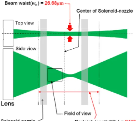
Fig. 1.은 측정영역으로 조사된 광원의 개략도
이다. 실험 장치와의 거리, 측정영역 위치를 고려
하여, Beam waist와 Rayleigh length를 구성해야 된 다(21). 레이저(Litron, Nd-Yag, Nano L 50-50 PIV,
England)의 초기 직경은 5mm로 식(1)에 의해 레이 저 직경을 줄일 수 있다. Fig. 2의 하단부에 있는 부분처럼 bi-convex 렌즈 4개를 조합하여 레이저 직경을 0.254mm로 줄였다. (1) 여기서
는 배율,
,
는 렌즈의 초점거리 이다.
>
면 확대,
<
면 축소이다. 직경을 0.254mm로 줄인 후, Sheet generating lens (30°)로시트를 형성하여 Illumination objective lens
(Mitutoyo 10x, N.A. 0.28, Working distance 34mm) 로 조사된다. 최종적으로 Beam waist( )는 식 (2) 에 의해서 26.68μm, Rayleigh length(
)는 식 (3) 에 의해서 약 8407μm이다. (2) (3) 여기서, 는 렌즈의 초점거리, 는 레이저 파 장,
는 렌즈의 직경이다.Fig. 1. Schematic of the light sheet, viewed from
top and side
2.2 Particle detection Setup
Fig. 2는 SPIM-μPIV 셋업의 개략도이다. Fig. 3 은 실제 셋업된 실험 장치이다. Detection objective 는 Illumination objective lens와 동일하게 수직 방향 으로 위치해있다. Detection objective lens 위에는 Prism과 mirror을 결합한 cubemirror가 위치해 있다. Detection objective lens 뒤쪽에 90도 미러가 위치해 있고, Tube lens, collimation lens와, Imaging lens를 순차적으로 통과하여 최종적으로 카메라로 들어 온다. Notch filter를 설치하여 벽과 공기방울에 의 한 레이저 산란과 다른 곳에서 반사되어진 광원을 제거하였다. Adjust mirror를 설치하여 광원이 CCD 로 정확하게 들어올 수 있게 하였다. 노출시간이 수십 ns로 짧고, 반사면적이 작은 관계로 Quantum
Efficiency(QE)값이 높은 카메라인 Electron Multiplying CCD(EM-CCD, Hamamatsu, 512x512, QE=99%, Japan)를 사용하였다. 레이저와 카메라 동기화 장 치는 Digital delay pulse generator(Model 505, 8 channel, BNC Nucleonics Corp., USA)이다. 이미지
캡쳐에 사용된 프로그램은 HCImage(Hamamatsu,
Japan)이다. EM-CCD 카메라는 double shutter가 불 가능하기 때문에 카메라 셔터가 열려 있는 동안 레이저 1,2가 조사된다. 레이저 시간 간격은 33μs 이다.
Fig. 2. Schematic of the SPIM-μPIV setup
Fig. 3. Particle detection setup 2.2 이상유동 시스템 폐열 회수 시스템과 동일한 유체 순환 시스템 을 구축하였다. Fig. 4는 이상유동을 순환 시스템 의 개략도이다. 노즐 하단부에 장착된 믹서를 통해 아래 부분에서 공기가 유입되고, 옆으로 물이 유입 된다. 물은 Reservoir로 돌아가 펌프로 재순환된다.
실험에 사용된 입자는 Fluorescent Magnetic Particles (Nominal size: 0.1-0.39μm, FCM-02558-2H, Spherotech, 0.1% w/v, USA)이다. 자성입자는 200ml deionized water와 혼합되며, 입자의 뭉침을 방지하기 위해 15분간 초음파 처리를 하였다. 이상유동 시스템을 순환하는 자성입자의 농도는 0.0005% w/v이다. Fig. 5는 노즐 형상, 유동 측정위치와 자기장 형태 를 나타낸 단면도이다. 입구 조건을 고려하여 Field of view(FOV)는 믹서 입구에서 약 320mm 지점이 다. 발전부 노즐은 내부 3x3x650(mm3), 벽 두께 5mm이며, 외부에 코일이 감겨 있다. 입구속도는 물 0.67m/s, Re 2000, 공기 0.093m/s, Re 18이다. 물 과 공기의 유량은 ratometer로 제어된다. 외부 자기 장 형성을 위해서 솔레노이드-노즐 외부에 220 x
110 x 45 (OD x ID x T, mm3), Neodymium, FOV
Fig. 4. Two-phase flow setup
Fig. 5. Cross-section of the solenoid nozzle and
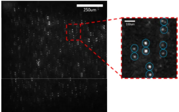
Magnetic field 3. 실험 결과 Fig. 6 버블 유동에서 공기방울 사이 간격이 넓 은 영역(wide)을 촬영한 영상이다. 카메라 셔터가 열려있는 동안 레이저 1,2가 조사되므로 영상에서 입자가 2개씩 있는 것을 알 수 있다. 측정영역은 벽면에서 200μm 떨어진 곳에서부터 중심방향까지 1200μm 이며 계산 영역은 1000 x 1000μm2이다. 버 블 유동 특성을 파악하기 위해 공기 방울 간격이 넓은 곳(wide), 좁은 곳(between), 벽면과 공기 방울 사이(side), 공기 방울 바로 밑(bottom) 총 4곳의 속 도를 계산하였다. Fig. 7은 각 공기 위치에 따른 계 산 영역을 나타낸 개략도이다.
Fig. 6. Raw image with magnetic field, wide gap
Fig. 7. Schematic of the calculation area
속도계산에 사용된 프로그램은 Davis(La Vision, Ver. 8.4.0, Germany)이고, 사용된 알고리즘은 Auto-correlation이다. Auto-correlation은 중심에 대 해 대칭인 두 개의 상관값을 가지므로 유동 방향 의 모호성이 발생하기 때문에 유동방향을 실험 수 행전 정할 필요가 있다. 본 연구에서는 실험 전 카 메라 방향을 미리 설정하여 유동방향을 결정하였 다. 유동 방향은 영상 아래쪽에서 위쪽이다. 영상 에서 공기 부분은 obstacle로 표시하여 계산 영역 에서 제외하였다. 계산 옵션은 decrease method, 상 관 영역 32x32, 16x16 pixel2이고 overlap 50%이다. Fig. 8은 외부 자기장이 있을 때 속도장이고, Fig. 9는 외부 자기장이 없을 때 속도장이다. x축 은 벽면에서 중심까지 거리를 나타낸다. 속도는 액 체의 입구속도로 무차원화하였다. 각 동일한 구역 별 속도장을 비교해보면 외부자기장이 있을 때와 없을 때의 속도차이는 작은 것을 알 수 있다. 이러 한 현상은 외부자력이 자성입자의 유동에 영향이 있었음에도 불구하고, 공기의 속도가 액체의 속도 에 비해서 상당히 느리기 때문에 외부 자기장의 영향에 따른 속도저하가 적게 미친 것으로 보인다.
(a) wide (b) between
(c) side (d) bottom
Fig. 8. Velocity fields of bubbly flow with
magnetic field
(a) wide (b) between
(c) side (d) bottom
Fig. 9. Velocity fields of bubbly flow without
magnetic field
(a) wide (b) between
(c) side (d) bottom
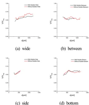
Fig. 10. Comparison of the average velocity profiles
Fig. 10은 각 속도장의 유동방향 속도를 평균한 속도 프로파일이다. 검은색 선이 외부 자기장이 있 을 때, 빨간선이 외부 자기장이 없을 때 속도 프로 파일이다. 버블 유동은 wide 8.95%, between 0.76%, side 1.65%, bottom 1.0%, 감소한 것으로 나타났다. 불확도는 Wieneke(22)의 알고리즘을 사용하는 Davis 프로그램에서 계산하였고, 불확도는 최대 0.2 pixel 이다. 4. 결 론 본 연구에서는 SPIM-μPIV를 이용하여 마이크 로급 입자의 속도 측정하였다. 대물렌즈로 수십 마 이크로 두께를 가진 시트를 형성하였고, z축으로 중첩되는 입자와 백그라운드 노이즈를 제거하였 다. SPIM-μPIV도 충분히 유체 유동 측정에 사용할 수 있고, 현미경 상에서 측정할 수 없는 환경에서 도 적용이 가능할 것으로 판단된다. 발전이 일어나 는 버블 유동에서 외부 자기장에 의해서 속도 저 하는 공기 사이 간격이 넓은 곳에서 최대 8.59%로 나타났다.
Nanoparticles During Magnetic Drug Targeting,” Journal of Nanotechnology in Engineering and Medicine, Vol. 6(1), pp. 011004
2) Hamdipoor, V., Afzal, M., Le, T.-A. and Yoon, J., 2018, “Haptic-Based Manipulation Scheme of Magnetic Nanoparticles in a Multi-Branch Blood Vessel for Targeted Drug Delivery,” Micromachines, Vol. 9(1), pp. 14.
3) Bibo, A., Masana, R., King, A., Li, G. and Daqaq, M. F., 2012, “Electromagnetic ferrofluid-based energy harvester,” Physics Letters, Section A: General, Atomic and Solid State Physics, Vol, 376(32), pp. 2163-2166.
4) Yun, H. R., Lee, D. J., Youn, J. R. and Song, Y. S., 2015, “Ferrohydrodynamic energy harvesting based on air droplet movement,” Nano Energy, Vol, 11, pp. 171-178.
5) Sheikholeslami, M., Barzegar Gerdroodbary, M., Mousavi, S. V., Ganji, D. D. and Moradi, R., 2018, “Heat transfer enhancement of ferrofluid inside an 90° elbow channel by non-uniform magnetic field,” Journal of Magnetism and Magnetic Materials, Vol. 460, pp. 302-311.
6) Hartshorne, H., Backhouse, C. J. and Lee, W. E., 2004, “Ferrofluid-based microchip pump and valve,” Sensors and Actuators, B: Chemical, Vol. 99(2–3), pp. 592-600.
7) Zeng, J., Deng, Y., Vedantam, P., Tzeng, T.-R. and Xuan, X., 2013, “Magnetic separation of particles and cells in ferrofluid flow through a straight microchannel using two offset magnets,” Journal of Magnetism and Magnetic Materials, Vol. 346, pp. 118-123.
8) Sheikholeslami, M. and Rokni, H.B., 2017, “Simulation of nanofluid heat transfer in presence of magnetic field: A review,” International Journal
Applied Microbiology and Biotechnology, Vol. 73, pp. 495-504.
10) Bibo, A., Masana, R., King, A., Li, G. and Daqaq, M. F., 2012, “Electromagnetic ferrofluid- based energy harvester,” Physics Letters, Section A: General, Atomic and Solid State Physics, Vol. 376(32), pp. 2163-2166.
11) Seol, M.-L., Jeon, S.-B., Han, J.-W. and Choi, Y.-K, 2017, “Ferrofluid-based triboelectric- electromagnetic hybrid generator for sensitive and sustainable vibration energy harvesting,” Nano Energy, Vol. 31, pp. 233-238.
12) Yun, H. R., Lee, D. J., Youn, J. R. and Song, Y. S., 2015, “Ferrohydrodynamic energy harvesting based on air droplet movement,” Nano Energy, Vol. 11, pp. 171-178.
13) Kim, S.H., Park, J.H., Choi, H.S. and Lee, S.H. (2017). “Power Generation Properties of Flow Nanogenerator With Mixture of Magnetic Nanofluid and Bubbles in Circulating System,” Ieee Transactions on Magnetics, Vol. 53(11). pp. 4600904
14) A. Kvon, Y.H. Lee, T.A. Cheema and C.W. Park, 2014, “Development of dual micro-PIV system for simultaneous velocity measurements: optical arrangement techniques and application to blood flow measurements,” Measurement Science and Technology, Vol. 25, pp. 75302.
15) B.H. Jun, N. Saikrishnan and A.P. Yoganathan, 2014, “Micro particle image velocimetry measurements of steady diastolic leakage flow in the hinge of a St. Jude Medical Regent mechanical heart valve,” Annals of Biomedical Engineering, Vol. 42, pp. 526-540.
16) Donata M. Fries, severin Waelchli and Philipp Rudolf von Rohr, 2008, “Gas–liquid two-phase flow in meandering microchannels,” Chemical
Engineering Journal, Vol 135, pp. S37-45. 17) J.G. Santiago, S.T. Wereley, C.D. Meinhart, D.J.
Beebe and R.J. Adrian, 1998, “A particle image velocimetry system for microfluidics,” Experiments in Fluids, Vol. 25, pp. 316-319
18) Raju Tomer, Matthew Lovett-Barron, Isaac Kauvar, Aaron Andalman, Vanessa M. Burns, Sethuraman Sankaran, Logan Grosenick, Michael Broxton, Samuel Yang, and Karl Deisseroth, 2015, “SPED Light Sheet Microscopy: Fast Mapping of Biological System Structure and Function,” Cell, Vol. 163 pp. 1796-1806.
19) Weijian Zong, Jia Zhao, Xuanyang Chen, Yuan Lin, Huixia Ren, Yunfeng Zhang, Ming Fan, Zhuan Zhou, Heping Cheng, Yujie Sun and Liangyi Chen, 2014, “Large-field high-resolution two-photon digital scanned light-sheet microscopy,” Cell Research, Vol. 25, pp. 254-257.
20) Zickus V. and Taylor JM., 2018, “3D + time blood flow mapping using SPIM-microPIV in the developing zebrafish heart,” BBiomedical Optics Express, vol. 9(5), pp. 2418-2435.
21) Engelbrecht, C. J. and Stelzer, E. H., 2006, “Resolution enhancement in a light-sheet-based microscope (SPIM),” Optics Letters, Vol. 31(10), pp. 1477-1479.
22) B. Wieneke, 2015, “PIV uncertainty quantification from correlation statistics,” Measurement Science and Technology. Vol. 26(7), pp. 074002