With the recent growth in smartphone services, the “mobile” environment has become a key factor to consider in the design of the future Internet. In this paper, we propose Mobile-Oriented Future Internet (MOFI), which is a new architecture for the future Internet for mobile-oriented environments. The MOFI architecture is designed with three functional features: global identifier and local locator in the identifier-locator separation, query-first data delivery for route optimization, and distributed control of identifier-locator mapping. The proposed architecture and functional operations are implemented and tested using the Linux platform. From the experiment results, we see that the MOFI architecture performs better than the existing identifier-locator separation schemes, such as Proxy Mobile IP and Host Identity Protocol, in terms of data throughout, mapping control overhead, and handover delay.
Keywords: Future Internet, architecture, local locator, query-first data delivery, distributed mapping control, implementation.
Manuscript received Apr. 30, 2012; revised Jan. 15, 2013; accepted Jan. 26, 2013. This research was supported by the IT R&D support program of KCA (KCA-10913-05004), the ITRC support program of NIPA (NIPA-H0301-12-2004) and the Basic Science Research Program of NRF (2010-0020926), and the Kyungpook National University Research Fund, 2012.
Ji-In Kim (phone: +82 53 950 7356, [email protected]) and Seok-Joo Koh (corresponding author, [email protected]) are with the School of Computer Science and Engineering, Kyungpook National University, Daegu, Rep. of Korea.
Heeyoung Jung ([email protected]) is with the Communications & Internet Research Laboratory, ETRI, Daejeon, Rep. of Korea.
http://dx.doi.org/10.4218/etrij.13.1812.0064
I. Introduction
With the popularity of smartphones and the emergence of various wireless networks, the network environment has rapidly changed from fixed-based to mobile-based. Mobile technology is expected to become dominant and very common in the near future [1]. With this trend, the mobile environment is now a primary factor to be considered in the design of the future Internet.
However, it should be noted that the Internet was originally designed for a fixed network environment rather than for a mobile network environment. This has resulted in various extensions being added to the Internet to satisfy mobility requirements, such as the Mobile IP (MIP) [2] and the Proxy MIP (PMIP) [3]. However, this patch-on approach is just a temporal heuristic rather than a permanent optimal solution.
Some efforts have been made to support Internet mobility in the transport layer, as shown with the Multipath Transmission Control Protocol (Multipath TCP) [4] and the Stream Control Transmission Protocol (SCTP) [5]. These transport-layer mobility schemes can be used to support the seamless handover for a multihoming host in mobile networks. However, such schemes do not consider the important mobility issues on identifier-locator (ID-LOC) mapping control and location tracking for mobile hosts (MHs).
Recently, the Host Identity Protocol (HIP) [6] and Locator/Identifier Separation Protocol (LISP) [7] were discussed for ID-LOC separation in the network layer. However, HIP and LISP depend on a centralized ID-LOC mapping system, such as Rendezvous Server (RVS) in HIP or Map Server in LISP. Regarding scalability, this centralized approach still has the drawback of traffic concentration at a central server [8].
Mobile Oriented Future Internet (MOFI):
Architectural Design and Implementations
Based on these observations, a variety of research projects emerged to design the future Internet, which included the development of eMobility [9], 4WARD [10], FIND [11], and MobilityFirst [12]. Each work was developed with its own distinctive features and design goals.
In this paper, we propose Mobile-Oriented Future Internet (MOFI), which is a new architecture for the future Internet that is a part of a project sponsored by the Korean government [13]. The MOFI architecture is designed with three functional features: Global ID and Local LOC (GILL), Query-First Data Delivery (QFDD), and Distributed ID-LOC Mapping System (DMS). In GILL, each host has a globally unique Host ID (HID), whereas a local or private IP address can be used as a LOC for packet routing within a network. In QFDD, the signaling operation for the LOC query is performed so as to obtain an optimal path before data transmission. In DMS, the ID-LOC mappings for hosts are managed by each access router (AR) in a distributed way.
With this MOFI architecture, in this paper, we describe the relevant data delivery and ID-LOC mapping control operations, which are implemented and tested using the Linux platform. This paper is organized as follows. In section II, we compare the main design features of the proposed MOFI and the existing ID-LOC separation schemes. Sections III and IV describe the architectural design of MOFI and the relevant control operations, respectively. In section V, we discuss a Linux-based implementation of MOFI. The performance analysis is given by experimentation in section VI. Finally, section VII concludes this paper.
II. Design Considerations
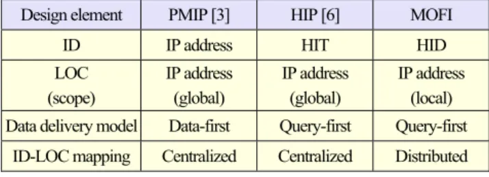
We first discuss the design features of MOFI respective to architecture. Table 1 compares the main features of MOFI with those of the existing PMIP and HIP schemes. We note that MIP is identical to PMIP, and LISP is similar to HIP regarding the ID-LOC separation principle.
1. Identifier and Locator
For mobility support in the network layer, the ID and LOC need to be separated, since an MH may change its LOC by movement, but its ID will not be changed. The ID-LOC separation approach is also taken in PMIP and HIP. In PMIP, the home address is used as the ID, and the care-of-address is used as LOC. In HIP, the Host Identity Tag (HIT) is used as the ID, and the IP address of a host is employed as the LOC.
In PMIP and HIP, a globally unique IP address is used as the LOC. However, this global uniqueness of the IP address may incur the well-known routing scalability problem in the BGP
Table 1. Comparison of ID-LOC separation schemes.
Design element PMIP [3] HIP [6] MOFI
ID IP address HIT HID
LOC (scope) IP address (global) IP address (global) IP address (local) Data delivery model Data-first Query-first Query-first
ID-LOC mapping Centralized Centralized Distributed
routing table, as discussed in the IRTF Routing Research Group [14].
In MOFI, an HID is used as the ID, which is similar to the HIT of HIP. The distinctive feature of MOFI is to use a local LOC, rather than a global LOC. That is, the end-to-end communication between two hosts is performed with their global IDs, whereas the data packets are delivered possibly via one or more networks by using local LOCs. Such LOCs may be local or private IP addresses, which are specific to the associated transit networks. With this local LOC feature, the routing scalability problem can be alleviated.
2. Data Delivery Model
In MIP or PMIP, all data packets destined to an MH are first delivered to the Home Agent or Local Mobility Anchor (LMA). This data-first feature induces a non-optimal path for data delivery between the two communicating hosts in the network.
In a mobile environment, a host frequently moves around in the networks. To use an optimal data path from the initial data transmission, we need to consider the query-first approach in the data delivery model. In this approach, the LOC query operation to find the location of an MH is performed before data transmission. This query-first approach is taken in MOFI as well as in HIP.
3. ID-LOC Mapping Control
Under the ID-LOC separation, one of the challenging issues is how to control the ID-LOC mapping information. PMIP and HIP use a centralized agent for ID-LOC mapping control, such as LMA of PMIP and RVS of HIP. In the centralized scheme, all of the ID-LOC mapping control messages are delivered to a centralized agent. Such centralized control schemes, however, tend to inject unnecessary traffic to the core network and may incur a traffic explosion problem. Moreover, the centralized approach is vulnerable to the failure of a central anchor [8].
To alleviate the problems of the centralized mapping system, we choose the distributed mapping control approach in MOFI. In the distributed mapping control, the mapping control traffic
2. Protocol Stack for Data Delivery will be distributed onto each AR in the network. Additionally,
security in the MOFI architecture may be another important
issue, which was discussed in previous work [15]. similar to the TCP/IP architecture. Figure 2 shows the protocol Regarding protocol stack, MOFI takes a layered model stack considered in MOFI. The current application layer, transport layer, and MAC/PHY protocols are reused in MOFI.
III. Architectural Design
As for the network layer, the current IP protocol performs end-to-end communication (by using a socket interface with the upper layer application) and data delivery (or routing). In MOFI, the network layer is divided into the following two sublayers: communication and delivery.
1. Global Host ID and Local Locator
As HIP uses an HIT, MOFI uses an HID to identify a host in the network, which is globally unique on the Internet. We consider the 128-bit HID format for compatibility with IPv6 application. The LOC is used for delivery of data packets. In MOFI, the LOC is defined as a locally routable IP address that must only be locally unique in the concerned network.
The communication sublayer is responsible for end-to-end communication between the two end hosts, which may be implemented as a shim layer protocol between transport and network layers. The delivery sublayer is responsible for packet routing in the access and backbone networks. The current IP routing schemes can be used for data packet routing.
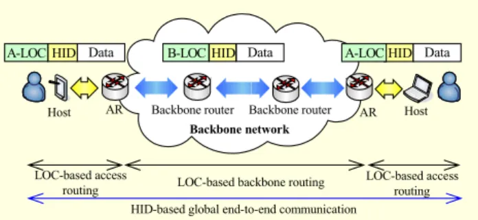
Figure 1 shows the data delivery operations with global HID-based communication and local LOC-based routing in MOFI. In the figure, the end-to-end communication between two hosts is performed with HIDs, whereas LOCs are used for
packet delivery in the access and backbone networks. 3. Query-First Data Delivery
To provide an optimal path for data delivery from the beginning, MOFI uses the query-first data delivery model. In this model, the LOC query operation is performed so as to find the current LOC of an MH before actual data transmission. For packet delivery, an access LOC (A-LOC, IP address of
the host) is used within the access network, whereas a backbone LOC (B-LOC, IP address of AR) is used in the backbone network. The data packet routing is performed locally in the access or backbone network, and each AR performs the LOC translation between the A-LOC and B-LOC.
Let us assume that the HID and LOC of an MH are registered with the HID-LOC mapping system. When a correspondent host sends a data packet to the MH, the AR of
Fig. 1. HID-based communication and LOC-based routing. Backbone network
AR Host
Data Data Data
Backbone router
LOC-based access
routing LOC-based backbone routing Backbone router
Host AR
LOC-based access routing HID-based global end-to-end communication
HID A-LOC B-LOC HID
HID A-LOC
Fig. 2. Protocol stacks for data delivery.
Application/transport
Network (IP address): end-to-end communication
& end-to-end data routing
MAC/PHY (a) Current TCP/IP
Application/transport Communication (HID): end-to-end communication
Delivery (LOC): local data routing MAC/PHY
(b) MOFI
Fig. 3. Query-first data delivery with mapping system.
Distributed HID-LOC mapping control system
LOC translation LOC translation
App./trans. HID A-LOC MAC/PHY
A-LOC B-LOC
MAC/PHY MAC/PHY backbone routing LOC-based
B-LOC A-LOC MAC/PHY MAC/PHY App./trans. HID A-LOC MAC/PHY HID-LOC binding & query LOC-based access routing LOC-based access routing HID-LOC binding & query HID-based end-to-end communication
the correspondent host will perform the LOC query operation with the mapping system to find the LOC of the MH. After that, the data packet is delivered to the MH by using the optimal route from the beginning.
Figure 3 shows the data delivery model with the distributed HID-LOC mapping control system. In the figure, each AR performs the LOC translation between the A-LOC and B-LOC. During this process, the source and destination HIDs are referred to by AR.
Figure 4 shows the encapsulation and LOC translation process in the data delivery model. For data delivery, each host encapsulates the data packet with the HIDs of source and destination hosts. Each AR translates LOCs between the A- LOC and B-LOC for data delivery in the access and backbone networks.
4. Distributed HID-LOC Mapping Control
In MOFI, the HID-LOC mapping control is done in the distributed way, in which each AR will perform the HID-LOC mapping control operations. In this paper, we consider the mapping control within a single network domain. The mapping control across different network domains is outside the scope of this paper.
Figure 5 shows a network model for the hash-based HID-LOC mapping control in MOFI. For HID-HID-LOC mapping control, each AR has a Local Mapping Controller (LMC) with a hash table and an HID-LOC Register (HLR). For a given HID, the LMC that is responsible for the mapping control of a
Fig. 4. Data packet encapsulation and LOC translation.
S-HID, D-HID Upper-layer headers Data
Data S-HID, D-HID Upper-layer headers
S-A-LOC, D-A-LOC
Data S-HID, D-HID Upper-layer headers
S-B-LOC, D-B-LOC
Data packet for end-to-end communication
Encapsulated data packet (at host)
Header (LOC) translation (at AR)
Fig. 5. Network model for HID-LOC mapping control.
LMC
LMC
LMC Hash-based HID-LOC mapping system
AR AR AR
Control Data
Host 2 Host 1 Access network Backbone network Access network
specific host is determined by the hash table. That is, the hash table is used to find the LMC that is in charge of the mapping control for the host. The HLR maintains the list of the HID-LOC bindings for the associated hosts. In this way, the HLRs are distributed onto ARs in the network. Each HLR is then updated in the HID-LOC binding operation and referred to in the LOC query operation, as described in the subsequent section.
IV. Mapping Control Operations
1. Control Messages
Table 2 shows the list of the messages used for HID-LOC mapping control in the proposed MOFI architecture. HID Binding Request (HBR)/HID Binding ACK (HBA) control messages are exchanged between host and AR or between ARs in the HID-LOC binding operation. LOC Query Request (LQR)/LOC Query ACK (LQA) messages are used in the LOC query operation, and LOC Update Request (LUR)/LOC Update ACK (LUA) messages are exchanged between ARs in the handover control operation. Each control message can be encapsulated into User Datagram Protocol (UDP) or Transmission Control Protocol (TCP).
2. HID-LOC Binding Operation
When a host is attached to the network, the HID-LOC binding operation is performed, in which the HID and LOC of a host is registered with the mapping control system. For this
Table 2. Control messages for mapping control.
Message Full name From To
HBR HID Binding Request Host/AR AR/AR HBA HID Binding ACK AR/AR AR/Host LQR LOC Query Request AR AR
LQA LOC Query ACK AR AR
LUR LOC Update Request AR AR
LUA LOC Update ACK AR AR
Fig. 6. HID-LOC binding operation.
Host LMC/AR
Hash table lookup LMC (HLR) HBR (HID: A-LOC) HBR (HID: B-LOC) HBA HBA HLR update
purpose, HBR and HBA messages are exchanged, as shown in Fig. 6.
When a host is attached to the network, the host registers its HID and A-LOC with LMC/AR by sending an HBR message. After that, the LMC/AR identifies the LMC that is in charge of the mapping control for the host, by using the hash table. Then, the LMC/AR sends an HBR message to the identified LMC. This HBR message contains the B-LOC, which is the IP address of AR. Based on the received HBR, LMC updates its HLR and responds with an HBA message to LMC/AR, and further to the host.
3. LOC Query Operation for Data Delivery
When a correspondent host (CH) sends a data packet to an MH, the LOC query operation is performed to find the current location of the MH. Figure 7 shows the LOC query operation for data delivery. For a description of the LOC query operation, we assume that a sending host (SH) is attached to LMC1 and a receiving host (RH) is connected to LMC3 and that another LMC2 is in charge of the HID-LOC binding for RH.
When a data packet arrives from the SH, the LMC 1 determines that LMC 2 is in charge of the mapping control, by using the hash table lookup. Then, LMC 1 sends an LQR message to LMC 2. On reception of the LQR message, LMC 2 looks up its HLR to find the current LOC of RH, LMC 3. After that, LMC 2 sends the LQR message to LMC 3. Then, LMC 3
Fig. 7. LOC query operation for data delivery.
SH LMC 1 LMC 2(HLR) LMC 3 RH
Data packets (A-LOC)
Hash table lookup
HLR lookup HID-LOC binding HID-LOC binding LQR LQR LQA
Data packets (A-LOC) Data packets (A-LOC) Data packets (B-LOC)
Data packets (A-LOC)
Data packets (B-LOC)
Fig. 8. LOC update for handover control.
Handover (to ARnew) LUR LUA Data packet LUR LUA Data packets
(C-HID & M-HID)
LUR LUA C-HID CH LMC/AR C-LOC M-LOCold LMC/ARold M-LOCnew LMC/ARnew M-HID MH Data packets
(C-HID: C-LOC & M-HID: M-LOCold) (C-HID & M-HID)Data packets HID binding (with ARold)
responds with an LQA message to LMC 1 of SH. Therefore, the AR of the SH can send the data packet directly to the AR of the RH by using the B-LOC, that is, the IP address of the AR of the RH.
When a data packet arrives at AR 3 (LMC 3), it is now delivered to the RH over the A-LOC. The subsequent data delivery can be performed between SH, AR 1, AR 3, and RH by using the A-LOCs and B-LOC along the data path, as shown in Fig. 7.
4. LOC Update Operation for Handover Control
The LOC update operation is performed for handover control. For a description, we assume that an MH is communicating with a CH, and the MH is moving from ARold to ARnew. By handover, ARnew can get information of ARold with the help of the IEEE 802.21 [16]. Figure 8 shows the handover control operation.
After handover, the MH performs the HID-LOC binding with LMCnew, in which the information of ARold is delivered to ARnew. Then, LMCnew exchanges the LUR and LUA messages with LMCold, so as to establish a handover tunnel between ARold and ARnew. By using the handover tunnel, the data packet of the CH is forwarded from ARold to ARnew.
Now, to provide a new optimal data path, LMCold exchanges the LUR and LUA messages with the LMC of the CH as well as LMCnew. The data path is now changed to the CH, the AR of the CH, ARnew of the MH, and the MH, and the handover control operation is complete.
V. Implementations over Linux Platform
For validation of the proposed MOFI architecture and the associated data delivery and mapping control operations, the host and LMC/AR are implemented using the Linux platform. 1. Host
For host implementation, we use the Ubuntu 10.04 and Linux kernel 2.6.32.16 version. The implementation of the host
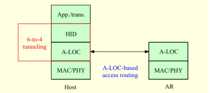
Fig. 9. Implementation stack at host.
Host AR HID App./trans. 6-to-4 tunneling A-LOC MAC/PHY A-LOC MAC/PHY A-LOC-based access routing
implementation in the host, in which the A-LOC is used for packet delivery between the host and the AR.
is done by using the 6-to-4 tunneling scheme [17]. For implementation, the IPv6 address for 6-to-4 tunneling is used as the HID, whereas the IPv4 address is employed as the A-LOC. The 128-bit HID includes a 2-byte prefix (2002) for 6-
to-4 tunneling. Figure 9 shows the protocol stack for 2. Access Router
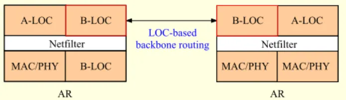
For implementation of the AR, we also use the Ubuntu 10.04 and Linux kernel 2.6.32.16 version. When a data packet arrives from a host, the AR translates the A-LOC to the B-LOC for the data packet. For this header translation, we employ netfilter and iptables [18].
Fig. 10. Implementation stack at AR.
AR Netfilter AR Netfilter A-LOC B-LOC MAC/PHY B-LOC B-LOC A-LOC MAC/PHY MAC/PHY LOC-based backbone routing
Figure 10 shows the protocol stacks for implementation using netfilter at the AR. It is noted that each AR performs the LOC query operation to find the LOC of the CH before data transmission.
Fig. 11. Netfilter modules used for AR implementation.
Datalink layer
ADP BDP
Find locator
Decapsulation (LOC) Encapsulation (LOC)
NF_IP_PRE_ROUTING NF_IP_POST_ROUTING
ip_rcv Ip_finish_output2
net_rx_action dw_queue_xmit
Figure 11 describes the netfilter functions to support the LOC translation at the AR. In the figure, the modified function modules (netfilter hooking points) are indicated as shared boxes.
In the figure, when a packet arrives from the host, the ip_rcv function is invoked to process the packet at the network layer. Then, the NF_IP_PRE_ROUTING function hooks the data packet. After that, the LOC is translated from the A-LOC to the B-LOC (or from the B-LOC to the A-LOC). When this LOC translation is complete, the NF_IP_POST_ROUTING function forwards the packet to the ip_finish_output2 function
Fig. 12. Testbed network configuration.
Hash-based HID-LOC mapping system
Host 1
Access network
Host 2
Access network ISP backbone network
LMC 1 LMC 2 LMC 3 Control Data AR 1 AR 2 AR 3 eth0 192.168.0.100 2002:aaaa:bbbb::1 eth1 192.168.0.1 eth0 155.230.105.215
IPv4 HID (IPv6) Data src:192.168.0.100
dst:192.168.0.1 src:2002:aaaa:bbbb::1 dst:2002:cccc:dddd::1
IPv4 HID (IPv6) Data src:155.230.105.215 dst:155.230.105.217 src:2002:aaaa:bbbb::1 dst:2002:cccc:dddd::1 eth0 155.230.105.217 192.168.0.1eth1 eth0 192.168.0.100 2002:cccc:dddd::1 IPv4 HID (IPv6) Data
src:192.168.0.1 dst:192.168.0.100 src:2002:aaaa:bbbb::1 dst:2002:cccc:dddd::1 eth0:1 155.230.105.214 eth0:1 155.230.105.216 eth0:1 155.230.105.218 eth0 155.230.105.219
Fig. 13. Testbed snapshot.
for data forwarding. It is noted that iptables is used together with netfilter. In MOFI, ipatbles is referred to during the packet forwarding to the AR.
3. Local Mapping Controller
For implementation of the hash-based mapping control at the LMC, we employ a simple hash function using a modulo (%) operator. That is, for a given HID, so as to determine the LMC that is responsible for the concerned host, we calculate “HID % (number of LMCs in the network).”
For this purpose, the LMCs in the domain are numbered in sequence. Then, the LMC that will be responsible for a host is selected as the LMC that has the equal sequence number to the resulting value of the modulo hash function. Once the LMC is determined in this way, the HID-LOC binding and LOC query operations can be performed with the determined LMC. In implementation, the mapping control messages are exchanged between LMCs by using UDP.
4. Testbed Configuration
Figure 12 shows the testbed network configuration, in which the two hosts (Host 1 and Host 2) and three ARs with LMCs (AR 1, AR 2, and AR 3) are employed.
In the testbed network, Host 1 acts as the video sender and Host 2 plays the role of the video receiver. Host 1 uses the HID of 2002:aaaa:bbbb::1, and Host 2 uses the HID of 2002:cccc:dddd::1. As for the LOC, private IPv4 address (192.168.x.y) is used as the A-LOC, and public IPv4 address (155.230.x.y) is used as the B-LOC.
Figure 13 shows a snapshot of the real machines associated with the testbed of Fig. 12. With this testbed, we perform two kinds of experimentation: validation of the local LOC-based data delivery model and the performance analysis of the distributed mapping control and handover control functions.
VI. Experiment and Analysis
1. Validation of Local LOC-Based Data Delivery
For validation of the local LOC-based data delivery model
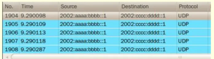
Fig. 14. Packet capture from AR 1 to AR 2.
Fig. 15. Packet capture from AR 2 to Host 2.
by implementation, we use the testbed given in Fig. 13. A simple video application over UDP is used as the upper layer application.
To analyze the data delivery, the following test scenario is applied. First, Host 1 and Host 2 are connected to AR 1 and AR 2, respectively. Then, Host 1 sends the data packet to Host 2. In this experiment, it is assumed that the HID-LOC binding and LOC query operations have already been completed. We have captured the data packets by using the Wireshark [19].
Figure 14 shows the packet capturing results for the data packets transmitted from AR 1 to AR 2. Similarly, Fig. 15 shows the data packets transmitted from AR 2 to Host 2. In the figures, we can see that Host 1 uses the HID of 2002:aaaa: bbbb::1 and that Host 2 uses the HID of 2002:cccc:dddd::1.
From the figures, we can also see that LOCs are translated along the path. In Fig. 14, AR 1 and AR 2 use 155.230.105.215 and 155.230.105.217 as LOCs (public IP addresses). In Fig. 15, the A-LOC of Host 2 is used with 192.168.0.100 (local or private IP address). In the meantime, the HIDs of Host 1 and Host 2 are not changed during the data delivery.
2. Performance Comparison for Mapping Control
Fig. 16. Testbed network for experiment analysis. RVS/LMA AR/MAG/LMC AR/MAG/LMC Mobile domain CN MN AR/MAG/LMC
Fig. 17. Signaling delays for HID binding and LOC query.
0 20 40 60 80 100 120 140 160 1 2 3 4 5 6 7 8 9 Number of hosts
Signaling delay for binding update (ms)
PMIP HIP MOFI
Fig. 18. Delays for LOC query and initial packet delivery by transmission delay between AR and central agent.
0 500 1,000 1,500 2,000 2,500 3,000 10 20 30 40 50 60 70 80 90 100
Transmission delay between ARs
Delay for query and initia
l data delivery (ms)
PMIP HIP MOFI
mapping control mechanism with the existing PMIP and HIP schemes. For performance comparison, we construct a testbed network, which consists of three ARs and one central agent (for the existing PMIP and HIP schemes), as shown in Fig. 16.
In the figure, the Mobile Access Gateway (MAG) of PMIP is co-located with the AR of MOFI, and the RVS of HIP is co-
`
Fig. 19. Delays for LOC query and initial packet delivery by transmission delay between AR and central agent.
0 1,000 2,000 3,000 4,000 5,000 6,000 7,000 8,000 9,000 20 40 60 80 100 120 140 160 180 200 Transmission delay between AR and centralized node
Delay for query
and initia
l data delivery
(ms) PMIP
HIP MOFI
located with the LMA of PMIP as a central agent. In the network, a mobile node (MN) is communicating with a correspondent node (CN) in the mobile domain.
Figure 17 shows the signaling delays required for the ID-LOC binding and ID-LOC query operations for the three candidate schemes. In this experiment, we gradually increase the number of MHs, each of which is attached to one of the three ARs with an equal probability.
From the figure, we can see that the proposed MOFI scheme provides a smaller signaling delay than the existing PMIP and HIP schemes provide. This is because the HID-LOC binding update and LOC query operations are processed by each AR in the proposed scheme, whereas all the control traffic should be processed by a central RVS or LMA in the existing schemes. In the meantime, PMIP performs better than HIP, since HIP performs the LOC query operation to obtain the LOC of an MN, whereas the data packets will be delivered to LMA without using the LOC query operation in PMIP.
Figure 18 compares the delay required for the LOC query and initial data delivery for the candidate schemes, as the transmission delay between ARs increases.
From the figure, we can see that the PMIP is not affected by the transmission delay between ARs, since the signaling path for the LOC query is performed between the AR and the LMA, and the data packet is delivered to the MN by way of the LMA. In the meantime, MOFI and HIP use the optimized data path after the LOC query operation, and the delays thus tend to increase as the transmission delay between ARs gets larger. It is noted that the proposed MOFI scheme gives smaller delays than the existing HIP scheme, since the LOC query operation is performed by each AR, not using the central agent.
Figure 19 shows the impacts of the transmission delay between the AR and the LMA (of PMIP) or RVS (of HIP) on the delays required for the LOC query and initial data delivery.
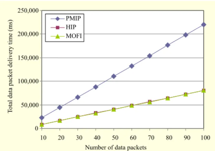
Fig. 20. Total data packet delivery time. 0 50,000 100,000 150,000 200,000 250,000 10 20 30 40 50 60 70 80 90 100
Number of data packets
To
tal data packet delivery time (ms)
PMIP HIP MOFI
Fig. 21. Number of control messages to be processed.
0 10 20 30 40 50 60 70 80 1 2 3 4 5 6 7 8 9 Number of hosts Number of messages to be processed at mapping controller PMIP HIP MOFI
As expected, the proposed MOFI scheme is not affected by the transmission delay between the AR and the LMA/RVS, since it does not use the central agent in the LOC query and data delivery operations. In PMIP, the delay is severely affected by the transmission delay between the AR and the LMA, since both the signaling path for the LOC query and the data path use the transmission link between the AR and the LMA. In the meantime, HIP uses the transmission link only for the LOC query operation. Thus, HIP provides better performance than PMIP.
As shown in Fig. 20, we compare the total data packet delivery time for the three candidate schemes. In this experiment, we increase the number of data packets. From the figure, we can see that HIP and MOFI perform better than PMIP. This is because these two schemes exploit the optimized path for data delivery, whereas PMIP depends on a non-optimal path via the central LMA. HIP performs nearly the same as MOFI. It is noted that the performance gap between PMIP and MOFI/HIP becomes larger as the number of data packets increases.
Fig. 22. Comparison of handover delays.
0 100 200 300 400 500 1 2 3 4 5 6 7 8 9 10 Handover trial
Handover delay (ms) PMIPHIP MOFI
To analyze the scalability by mapping control operations, we measure the number of control messages to be processed at the mapping controller (that is, LMA of PMIP, RVS of HIP, and LMC/AR of MOFI), as shown in Fig. 21. In the figure, we can see that the number of control messages to be processed becomes larger as the number of hosts increases in the network for all of the candidate schemes.
From the figure, we can also see that the proposed MOFI scheme can reduce the overhead of control messages required for mapping control, compared to the existing PMIP and HIP schemes. This is because the MOFI scheme is based on the distributed mapping control at each AR/LMC, and the control messages to be processed thus tend to be equally distributed over each AR/LMC. On the other hand, HIP and PMIP rely on the central LMA or RVS for the ID-LOC binding update and LOC query operations. Compared to the HIP scheme, the PMIP scheme tends to generate fewer control messages, since PMIP performs only the ID-LOC binding update operation, not using the LOC query operation. Overall, out of HIP, PMIP, and the proposed MOFI scheme, MOFI gives the best performance. This performance gain tends to increase as the number of hosts increases.
3. Performance Comparison for Handover Control
We now analyze the handover control performance for the three candidate schemes. For the handover experiment, an MN moves from AR 1 to AR 2 during data communication. For the experiment, we measure the handover delay that an MN experiences during handover, which is defined as the gap of the reception times between the last data packet in the old AR and the first data packet in the new AR.
Figure 22 shows the handover delays for the three candidate schemes over 10 handover trials. From the figure, we can see that the proposed MOFI scheme gives a smaller handover delay than the existing HIP and PMIP schemes. On average,
the proposed MOFI scheme gives handover delays of less than 300 ms for all the handover trials, whereas the HIP and PMIP schemes provide approximately 340 ms and 430 ms, respectively. This is because MOFI performs the LOC update operations between the two neighboring ARs for handover control, whereas the HIP handover scheme relies on the remote host [20] and the PMIP handover scheme depends on the central LMA [21] so as to update the changed LOC information during handover. Moreover, PMIP gives larger handover delays than HIP, since the LMA of PMIP updates the changed LOC with both the MAG of the CN and the MAG of the MN.
VII. Conclusion
In this paper, we presented a new architecture for the future Internet for mobile environments. The proposed architecture provides a set of distinctive features: GILL, QFDD, and DMS.
To evaluate the proposed architecture, we implemented the proposed MOFI architecture and its control operations over the Linux testbed. From the testbed experimentation, we see that the local LOC-based data delivery model can be implemented and used for enhancement of the routing scalability. From the performance analysis of the proposed distributed ID-LOC mapping control, we can see that the proposed MOFI scheme performs better than the existing HIP and PMIP schemes for a variety of mobile network environments, in terms of signaling delays required for ID-LOC binding and LOC query operations, data transmission throughput, number of signaling messages for mapping control, and handover delay.
For further study, we need to validate the MOFI architecture over real-world networks by considering various mobile network environments.
References
[1] Cisco Virtual Networking Index: Global Mobile Data Traffic Forecast Update 2011-2016, Feb. 2012.
[2] C. Perkins et al., “Mobility Support in IPv6,” IETF RFC 6275, July 2011.
[3] S. Gundavelli et al., “Proxy Mobile IPv6,” IETF RFC 5213, Aug. 2008.
[4] A. Ford et al., “Architectural Guidelines for Multipath TCP Development,” IETF RFC 6182, Mar. 2011.
[5] R. Stewart et al., “Stream Control Transmission Protocol (SCTP) Dynamic Address Reconfiguration,” IETF RFC 5061, Sept. 2009. [6] R. Moskowitz et al., “Host Identity Protocol,” IETF RFC 5201,
Apr. 2008.
[7] D. Farinacci et al., “Locator/ID Separation Protocol,” IETF Internet Draft, draft-ietf-lisp-23, May 2012.
[8] H. Chan et al., “Requirements of Distributed Mobility Management,” IETF Internet Draft, draft-ietf-dmm-requirements-03, Dec. 2012.
[9] eMobility Project. http://www.emobility.eu.org/ [10] 4WARD Project. http://www.4ward-project.eu/ [11] Future Internet Design (FIND). http://www.nets-find.net/ [12] Mobility First: Future Internet Architecture. http://mobilityfirst.
winlab.rutgers.edu/
[13] Mobile Oriented Future Internet (MOFI). http://www.mofi.re.kr [14] D. Meyer et al., “Report from the IAB Workshop on Routing and
Addressing,” IETF RFC 4984, 2007.
[15] P. MARTINEZ-JULIA et al., “Evaluating Secure Identification in the Mobile Oriented Future Internet (MOFI) Architecture,” Conf. Future Netw. Mobile Summit, Berlin, Germany, July 4-6, 2012. [16] IEEE 802.21, Media Independent Handover Services. [17] 6-to-4 tunneling. http://en.wikipedia.org/wiki/6to4/ [18] Linux netfilter hacking HOWTO, July 2002. [19] Wireshark. http://www.wireshark.org
[20] P. Nikander et al., “End-Host Mobility and Multihoming with the Host Identity Protocol,” IETF RFC 5206, Apr. 2008.
[21] S. Krishnan et al., “Localized Routing for Proxy Mobile IPv6,” IETF RFC 6705, Sept. 2012.
Ji-In Kim received his BS and MS in electrical engineering and computer science from Kyungpook National University, Daegu, Rep. of Korea, in 2008 and 2010, respectively. He is currently a PhD student with the School of Computer Science and Engineering, Kyungpook National University, Rep. of Korea. His current research interests include wireless communication, Internet mobility, and the future Internet.
Heeyoung Jung joined ETRI, Daejeon, Rep. of Korea, in 1991, after receiving his BS from Pusan National University (PNU), Busan, Rep. of Korea, and is currently a principal research member. He received his PhD in information and communications engineering from Chungnam National University (CNU), Daejeon, Rep. of Korea, in 2004. His major research areas include the Internet, mobile network technologies, and standardization in ITU-T, IETF, and so on. His current research topic is future Internet architecture.
Seok-Joo Koh received his BS and MS in management science from the Korea Advanced Institute of Science and Technology (KAIST), Daejeon, Rep. of Korea, in 1992 and 1994, respectively. He received his PhD in industrial engineering from KAIST in 1998. From August 1998 to February 2004, he worked for the Protocol Engineering Center, ETRI, Daejeon, Rep. of Korea. He has been a professor with the School of Computer Science and Engineering, Kyungpook National University, Daegu, Rep. of Korea, since March 2004. His current research interests include mobility management in the future Internet, IP mobility, multicasting, and SCTP. He has so far participated in international standardization as an editor for ITU-T SG13 and ISO/IEC JTC1/SC6.