Stress Analysis of IPS Lower bracket
J. M. Lee, K. N. Park, D. Y. Chi, S. K. Park, B. S. Sim, H.H. Lee, S. H. Ahn, C. Y. Lee, H. R. Kim HANARO Utilization Technology Division, 3-Pin Fuel Test Loop R&D Department, Korea Atomic Energy
Research Institute, P. O. B 105, Yuseong, Daejeon, 305-353 [email protected]
1. Introduction
The 3-Pin Fuel Test Loop (FTL) is a facility which could conduct fuel irradiation test at HANARO. It is composed of and In-Pile test Section (IPS) and an Out-of-Pile System (OPS).
Restraint of the IPS from self-weight and seismic loads is achieved by its support system. The one is box beam in pool-wall and the other is lower bracket on the mounting plate. This study describes the lower bracket stresses for seismic loading and the design & manufacturing of mounting plate mock-up for the as-built measurement of the HANARO reactor.
2. Model and Code Requirements
The lower bracket (Fig 1) is mounted on the top plate of the reflector tank and its arm locates around the IPS to limit movement of it. The arm is hinged so that it can be moved out of the way to allow adequate access to the reactor core for reactor fuel element changes.
Fig.1 Lower Bracket of IPS
The supports considered are treated as “Linear-Type” supports (NF-1213) because they are acting under essentially a single component of direct stress. Linear type supports can be analyzed elastically based on maximum stress theory (NF-3143). When seismic loading is present the situation is somewhat more complicated but generally the predominant loads are
bending in two axes and the two components of tensile bending stress can be added. Where shear (direct and torsion) stresses are significant the rules of NF-3300 have been supplemented by checks on the equivalent stress comparing it with an allowable stress of 0.6 x Yield Stress. Thus for acceptability:
Equivalent stress = √(σ2 + 4τ2) ≤ 0.6 σy
ASME III NF requires design by analysis, with stresses in components satisfying acceptance criteria. Table 1 summarizes the relevant paragraphs which specify the stress limits applicable to the supports for linear type supports.
Table 1 Code Paragraphs specifying Stress Limits
Design by Analysis Bolting Weld Joints Class 3 Piping Support NF-3360 NF-3653 F-1334 NF-3324 NF-3655 F-1335 NF-3324 NF-3556 F-1334
Allowable stresses are based on yield stress and tensile strength at temperature. Table 2 below gives the relevant values of yield stress and tensile strength for the main support materials from Table U and Table Y-1 of ASME II.
Table 2 Material strength of 316L
Yield Strength (Sy) Tensile Strength (Su) Stress Intensity (Sm) 146.9 MPa 469.5 MPa 89.6 MPa
The normal temperature of the supports is in the range 40oC to 50oC, but a maximum pool water temperature of 93oC (200oF) under accident conditions is assumed and used for the assessment.
3. Service Loadings
The principal loadings on the IPS Support Frame are: • Weight of the IPS Support Frame and IPS • Seismic loads
• Pipe break loads
In order to simplify the analysis, two enveloping load cases were considered:
Transactions of the Korean Nuclear Society Autumn Meeting Busan, Korea, October 27-28, 2005
• Case 1 where the Service Level B OBE loads (assumed identical to the SSE load) were combined with Service Level A loads and the Level C Room 1 pipe break load, with acceptance based on code allowable stresses for Service Level A.
• Case 2, in which the loadings for the Service Level D in-pool pipe break event was combined with Level A loads, with acceptance based on code allowable stresses for Service Level D as defined in ASME III Appendix F.
4. Conclusion
The only load for Service Level A is approximately 100 N upward hydraulic thrust due to the flow of reactor coolant water which does not give rise to any significant stress in the lower bracket components.
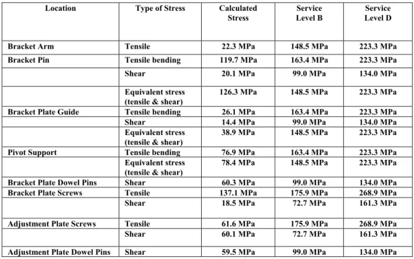
The only significant loading on the lower bracket support is the lateral seismic load due to seismic movement of the IPS. A single case is considered; that due to a SSE, which envelopes the loading from an OBE. The analysis assumes that this load could act in any direction in the horizontal plane. The results for the locations with the smallest margins relative to code allowable are given in Table 3 below.
REFERENCES
[1] ASME Boiler and Pressure Vessel Code, Section III NF, 2001
[2] Design Report for Supports (for IPS & Piping), HAN-FL-E-320-RT-R002, Rev. 0, 2005.
[3] Hydraulic Loads on In-Pool Piping, HAN-FL-E-340-RT-R003, Rev. 0, 2005.
Table 3 Lower Bracket Stress for Seismic Loading
Location Type of Stress Calculated
Stress
Service Level B
Service Level D
Bracket Arm Tensile 22.3 MPa 148.5 MPa 223.3 MPa
Bracket Pin Tensile bending 119.7 MPa 163.4 MPa 223.3 MPa
Shear 20.1 MPa 99.0 MPa 134.0 MPa
Equivalent stress (tensile & shear)
126.3 MPa 148.5 MPa 223.3 MPa
Bracket Plate Guide Tensile bending 26.1 MPa 163.4 MPa 223.3 MPa
Shear 14.4 MPa 99.0 MPa 134.0 MPa
Equivalent stress (tensile & shear)
38.9 MPa 148.5 MPa 223.3 MPa
Pivot Support Tensile bending 76.9 MPa 163.4 MPa 223.3 MPa
Equivalent stress (tensile & shear)
78.4 MPa 148.5 MPa 223.3 MPa
Bracket Plate Dowel Pins Shear 60.3 MPa 99.0 MPa 134.0 MPa
Bracket Plate Screws Tensile 137.1 MPa 175.9 MPa 268.9 MPa
Shear 18.5 MPa 72.7 MPa 161.3 MPa
Adjustment Plate Screws Tensile 61.6 MPa 175.9 MPa 268.9 MPa
Shear 60.1 MPa 72.7 MPa 161.3 MPa