I. Introduction
An increasing number of researches and developments for unmanned and intelligent vehicle systems are attracting a lot of attention and interest industrially and academ- ically during the past decade. Furthermore, the development of intelligent vehicle system is intensively fostered as strategic industry.
These researches can be applied in a variety of fields such as military surveillance and transport, terrain mapping, hazardous environ- ment, and commercial vehicle safety [1].
Many unmanned systems have been designed and built keeping compatibility with the Joint Architecture for Unmanned Systems (JAUS) reference architecture. The JAUS is an
architecture specified for use in research, development, and acquisition primarily for unmanned systems. The purpose of JAUS is interoperability with an emphasis on the logical communications between heterogeneous com- puting systems used for unmanned systems command and control. JAUS seeks to achieve this purpose through the development of functionally cohesive building blocks called components whose interface messages are clearly defined [2].
In this paper, we describe the design and implementation of UGV and also estimate how well the autonomous navigation and remote control of UGV can be performed through the optimistic arbitration of several sensor data, which are acquired from vision, obstacle detection, and positioning system. For an additional operation, remote control, two types of experimental environments were established.
one is to use a commercial racing wheel module and the other is to use a haptic device that is useful for a user application based on virtual reality.
논문 2008-03-31
Development of an Autonomous Navigation System for Unmanned Ground Vehicle
Yoon-Gu Kim, Ki-Dong Lee*
Abstract: This paper describes the design and implementation of an unmanned ground vehicle (UGV) and also estimates how well autonomous navigation and remote control of UGV can be performed through the optimized arbitration of several sensor data, which are acquired from vision, obstacle detection, positioning system, etc. For the autonomous navigation, lane detection and tracing, global positioning, and obstacle avoidance are necessarily required. In addition, for the remote control, two types of experimental environments are established. One is to use a commercial racing wheel module, and the other is to use a haptic device that is useful for a user application based on virtual reality. Experimental results show that autonomous navigation and remote control of the designed UGV can be achieved with more effectiveness and accuracy using the proper arbitration of sensor data and navigation plan.
Keywords: unmanned vehicle, autonomous navigation, lane detection, obstacle avoidance
* Corresponding Author
Manuscript received April 22, 2008; accepted August 14, 2008.
Yoon-Gu Kim : Daegu Gyeongbuk Institute of Science and Technology(DGIST).
Ki-Dong Lee : Dept. CS in Yeungnam Univ.
. Unmanned Vehicle System
Ⅱ
As shown in Fig. 1, our unmanned vehicle system is comprised of a main control system and several subsystems such as vision system, obstacle detection, positioning system, driving control, autonomous navigation, and remote control. The more detailed development processes are mentioned in the following subsections.
Fig. 1. System configuration of UGV.
1. Main Control System (MCS)
Main control system plays the most important role of intelligent UGV that is to arbitrate the whole control system. The detailed role of MCS is to acquire vision, obstacle detection, and global positioning information respectively from each subsystem, and then to determine how to drive UGV by unmanned control without artificial operation.
MCS is composed of hardware based on NI-PXI series that includes PXI-1042 8-slot 3U PXI Chassis with Universal AC, PXI-8186 2.2 GHz Pentium 4 Embedded Controller for PXI, PXI-8252 IEEE 1394 Interface Board, PXI-6070E 1.25 MS/s, 12-Bit, 16 Analog Input Multi-function DAQ, 2 analog outputs, 8 digital I/O lines, two 24-bit counters, analog triggering. MCS is operated by LabVIEW application programs based on Windows XP.
2. Vision System
The vision system of UGV has the capability to recognize the surrounding environment, especially detecting lanes or features of road. The result of vision processing provides a steering command of moving direction. UGV is equipped with 2 sets of digital cameras, whose model is Marlin F-033 of ALLIED Vision Technologies (AVT), and a PXI-8252 IEEE 1394 interface board for vision system, and UGV also uses a wireless image transmission device and a CCD camera in order to acquire the real surrounding images for remote control.
3. Obstacle Detection System
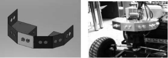
Obstacle detection system (ODS) of UGV is comprised of 7 ultra sonic sensors and an 8-Mhz Atmel ATmega128L embedded controller with 4 Kbytes of RAM and 128 Kbytes of ROM. Each sensor of ODS is calibrated to detect obstacles within about 3m in front of UGV because each sensor generates different sensing output although it has the same specification and model. The detection data of 7 sensors are transmitted to MCS via RS232 and used for calculating a steering angle for the obstacle avoidance of UGV. Seven ultrasonic sensors are attached to the disposition frame shown in Fig. 2. Each disposition angle of sensor array is around 25 degrees that is a reasonable detection angle of an ultrasonic sensor to detect the surrounding in front of UGV without any blind spot.
Fig. 2. Disposition frame of 7 ultrasonic sensors.
4. Positioning System
Global positioning system (GPS) has been used necessarily to recognize the global position of previous automobile navigation systems. However, since the measurement error of a single GPS normally shows 1~10m until now, it is not available to be utilized firsthand in the automobile navigation. Map matching method is usually used to compensate for that error by software. It means that the vehicle can recognize as being driven on a specific road when the changes of position and direction in the coordinates are considered, even though the GPS coordinates do not correspond to the road map correctly.
Differential GPS (DGPS) or Real Time Kinematics (RTK) GPS is used for complementing the demerit of single GPS. Both methods compensate for the measurement position data by using the reference data that the reference station transmits. RTK is more accurate but very expensive. UGV is also equipped with a GPS, AEK-4R, which is a kind of dead-reckoning (DR) GPS receiver. The GPS model supplements the positioning infor- mation with additional sensing data from a gyroscope and an odometer to establish the traveled route during periods of poor GPS reception or GPS outage. Since the accuracy of GPS data depends on the quality of available GPS signals, AEK-4R applies its own enhanced Kalman filter (EKF) algorithm to accurately compute the next positions by using an automatically weighted mix of GPS and sensor inputs [3].
5. Driving Control
The basic elements for driving control of UGV are comprised of speed and brake for longitudinal control, and steering for lateral control. For the vehicle platform of our UGV, we remodeled a commercial mobility scooter, Repow RP-414 [4], instead of newly manufacturing itself. The key specifications and
Table 1.
Table 1. Specifications of Repow RP-414.
Dimensions 1,200 x 620 x 980mm Ground clearance 90mm
Net weight 85kg(including 2 batteries:26kg) Max. forward speed 12kph
Climbing capability 12 degrees
Turning radius 1.6m
Motor 24V and 450W
Battery 12V and 38Ah x 2 Front tire, Rear tire 10 x 3.5, 14 x 2.5(inches) Running distance on
one full charge 45km
5.1 Speed and brake control
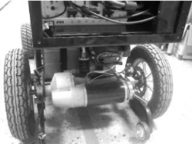
The speed control of UGV is controlled by pulse-width modulation (PWM) signal that is generated according to the current speed determined and commanded by MCS. The PWM control takes the place of the speed control lever of vehicle. For the brake system, UGV is equipped with each disc brake on both real wheels for slowing or stopping the rotation of wheels. The existing brake control lever mechanically actuates the brake pad of disc by pulling the cable. Therefore, the lever-actuated brake system was replaced by a method to electrically actuate the brake pad by using a DC geared motor. The driving motor and brake disc are shown in Fig. 3.
Fig. 3. Driving motor and brake disc.
5.2 Steering control
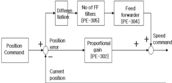
Fig. 4 shows the steering control system accomplished by mounting a 200W AC servo motor using intermeshing gears with the gear ratio of 1:1 and a reducer with the gear ratio of 10:1. The angular displacement, velocity, and acceleration for the required steering control of MCS are transmitted to a servo drive device with the specified protocol by a wired communication, RS232C. The servo drive actuates the servo motor so that the steering wheel of UGV is located to the commanded steering angle. The servo drive is a type of rotary coordinate position operation. Fig. 5 shows the operation flowchart of servo drive, APD-VP02N (MECAPION) [5].
Fig. 4. Steering control system embodied by using servo motor and driver.
Fig. 5. Operation flowchart of servo drive.
6. Autonomous Navigation
The autonomous navigation of UGV can be performed by major functions such as lane detection, obstacle avoidance, path-planning, and so forth. These functions are implemented through the optimized process of respective
sensor data that are acquired from vision, ODS, positioning system, etc. The vision data are used to determine a normal steering angle for driving roads with obvious lanes. The ODS data are used to determine a secondary steering angle and speed that take precedence of the normal ones, when an obstacle is detected. The positioning data are usually used for path planning of UGV. The detailed implementations of these functions are described in the next chapter.
7. Remote Control
Two types of experimental environments for remote control have been established. The first one is to use a commercial racing simulation module, Logitech G25 Racing Wheel, and the other one is to use a haptic device, PHANTOM Omni developer kit [6], which is useful to enable a user application based on virtual reality. The racing wheel enables a user to control more precise and realistic driving with dual-motor force feedback, 900-degree steering and a six-speed gated shifter. While a user is operating the remote control system with monitoring the status of UGV that includes vehicle speed and pose, surrounding image, global position and so on, the operating information such as steering, speed, brake, and gear shift are transmitted to MCS via a wireless communication by LM2400, 2.4Ghz Zigbee RF module (RadioPulse) [7].
. Implementation and Navigation
Ⅲ
All software applications for the major functions of UGV are implemented by NI LabVIEW that is a development tool with merits to rapidly and effectively interface with measurement and control hardware, analyze data, share results, and distribute systems.
That explains why LabVIEW was selected for development of our UGV application. The major functions include lane detection, obstacle avoidance, and path planning.
1. Lane Detection
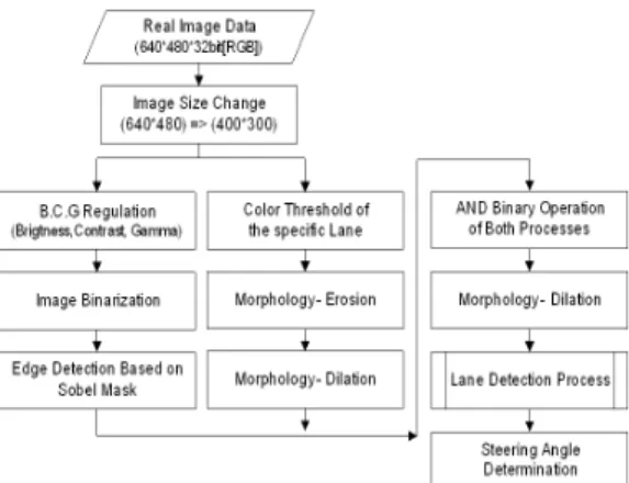
It is necessarily required for UGV to have a faculty to detect the lane in front of a current heading and determine its steering angle through processing the real-time image of vision system. As shown in Fig. 6, the real image data are processed by two other image processing. One is the edge detection based on Sobel mask, and the other is the noise removal based on mathematical morphology. Both process results are combined by AND binary operation and once again processed by dilation, one of the basic morphology operations once again. The lane detection by using the processed result is basically carried out by a LabVIEW function, IMAQ Find Vertical Edge, only in the region of interest (ROI) from the processed image. As a result, the steering angle required at the next control time is determined.
Fig. 6. Lane detection and steering control by image processing of vision system.
2. Obstacle Avoidance
The obstacle avoidance system implements an ability to avoid stationary or moving obstacles detected on the navigation course and return to the normal route. The detection data received from ODS is used to calculate a steering angle in the obstacle avoidance mode of UGV. A steering angle for the optimal
how many sensors detect the obstacle and how far the obstacle is from UGV. That is implemented by a sub-VI of LabVIEW. The basic algorithms for obstacle detection and avoidance are Grid Certainty [8, 9] and Virtual Force Field (VFF) [10]. As a result, MCS instructs the steering angle for obstacle avoidance in preference to the steering angle determined by vision system.
3. Path Planning
For path planning, UGV must recognize where it is right now and how it reaches a target position. As a precondition, it is assumed that the grid-based map of specific area is given. During the real autonomous navigation, the heading determined by the image processing of vision system is normally instructed to the steering control system. On the other hand, in the case that the obvious lane detection is not available, the optimal desired heading is estimated by corresponding the global position of GPS to the spatial local grid map. For doing this, both relative and absolute localization methods must be considered simultaneously for the autonomous navigation. The general GPS does not provide the accurate position enough for UGV to navigate following the general lane. The local sensors such as encoder, gyroscope, and tilt sensor are used to relatively compensate the current pose of UGV.
4. Navigation Modes 4.1 Autonomous navigation
For autonomous navigation, MCS has to arbitrate and concatenate organically the main functions such as localization, lane detection, obstacle avoidance, and path planning. Fig. 7 shows the main VI hierarchy of autonomous navigation system implemented by LabVIEW.
The main functions are multi-threaded by possessing each own timed-loop operation. It is important to guarantee the real-time operation
of each function by assigning the proper loop times.
Fig. 7. VI hierarchy of autonomous navigation system.
4.2 Remote control navigation
Fig. 8 shows the user applications and experimental environments for remote control navigation as mentioned previously. The upper one enables a user to drive UGV with more realistic sensation by handling the commercial racing wheel device. The lower one shows the remote control navigation is possible in a virtual reality implemented by using the haptic device.
IV. Experiment and Analysis
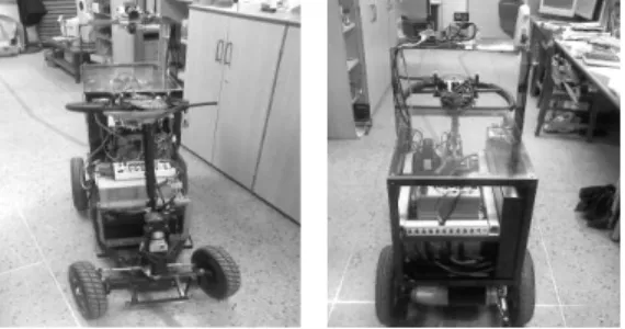
The front and rear side of the developed UGV are shown in Fig. 9. Our experiments have been carried out in the indoor environment because the development is currently on the way. Firstly, UGV was tested fulfilling the duty to follow a specific line and arrive at the target position in the laboratory.
During following the line, the steering angle determined by the current image frame is only stored at the queue memory of MCS instead of being directly applied to the steering control system, because the acquired image is the state of line ahead of about 3m from UGV.
Therefore, a steering angle in the queue is selected and instructed according to the current speed and pose of UGV.
(a) (b)
(c) (d)
Fig. 8. Remote control experiments of UGV based on the commercial racing wheel (a, b) and
the haptic device (c, d).
Fig. 9. Front and rear side of UGV following an experimental line.
Fig. 10 shows the line detection and steering angle calculation within ROI through the image processing of vision system. Our experimental results have verified that UGV can be navigated with line detection and obstacle avoidance in the indoor environment.
In the case of remote control, the remote control based on the racing wheel was operated naturally as the user became accustomed to the simulation application, while the remote control based on the haptic device revealed a little unnatural operation because of limitation to usability of haptic device.
Fig. 10. Image processing, line detection, and steering angle determination of UGV.
V. Conclusion
This paper has described the process by which an autonomous navigation system for UGV was designed and developed, and the implementation of major operation functions such as lane detection, obstacle avoidance, path-planning, and autonomous or remote control has been described also.
Considering the dynamic and variant envi- ronmental elements, further study will be focused on endowing UGV with much advanced intelligence for more robust autonomous navigation and safety.
References
[1] S. Kim, T. Galluzzo, D. Macarthur, D. Kent, S. Solanki, E. Zawodny, J. H. Kim, and C. D.
Crane III, "Design of an Unmanned Ground Vehicle, Tailgator Theory and Practice,"
International Journal of Automotive Technology, Vol. 7, No. 1, pp. 83-90, 2006.
[2] "The Joint Architecture for Unmanned Systems – Compliance Specification (CS),"
Ver. 1.2, Oct. 2006.
[3] AEK-4R, http://www.u-blox.com.
[4] Mobility scooter RP-414,
http://repow.manufacturer.globalsources.com.
[5] APD-VP Series, http://www.mecapion.com.
[6] PHANTOM Omni Developer Kit, SensAble
Technologies, http://www.sensable.com.
[7] ZigBeeTM solution LM2400, RadioPulse Inc., http://www.radiopulse.co.kr.
[8] A. Elfes. "Using occupancy grids for mobile robot perception and navigation," IEEE Computer, Vol. 22, pp. 46-57, 1989.
[9] Wilfried Elmenreich, "Fault-Tolerant Certainty Grid," Proceedings of the 11th International Conference on Advanced Robotics, Vol. 3, pp.
1576-1581, June 2003.
[10] Johann Borenstein, "Real-Time Obstacle Avoidance for Fast Mobile Robots," IEEE Transactions on Systems, Man and Cybernetics, Vol. 19, No. 5, pp. 1179-1187, September/ October 1989.
BIOGRAPHY
Yoon-Gu Kim
received the M.S. and Ph.D. degrees in Computer Engi- neering
from Yeungnam
University in 2005 and 2008, respectively.
He is now a post doctor research engineer of Daegu Gyeongbuk Institute of Science and Technology (DGIST).
His research interests include robotics, sensor network, intelligent unmanned vehicle, and GPS.
Email : [email protected] Ki-Dong Lee
received the M.S. and Ph.D. degrees from Seoul National Univ. in
1987 and 1994,
respectively. He is currently a Prof. of CS in Yeungnam University.
His research interests focus on robotics, sensor network, artificial intelligence, and information security.
Email : [email protected]