DOI http://dx.doi.org/10.9725/kstle.2015.31.1.21
Characteristic of Friction on Texturing Bearing Steel with Ultrasonic Hole Machine
Mijung Shin, Angga Senoaji H, SoonHong Kwon, SungWon Chung, SoonGoo Kwon, JongMin Park, JongSoon Kim and WonSik Choi†
Department Bio-Industrial Machinery Engineering Pusan National University, Korea (Received; November 09, 2014; Received; January 3, 2015; Received; January 5, 2015)
Abstract − We carry out experiments to characterize textured bearing steel with varying hole density and depth.
Textured surface is believed to reduce the friction coefficient, and improve performance and wearing caused by third-body contact. We employ three lubrication regime conditions based on the Stribeck curve: boundary lubri- cation, mixed lubrication, and hydrodynamic lubrication. Ultrasonic machining is an untraditional machining method wherein abrasive grit particles are used. The hammering process on the work piece surface by abrasive provides the desired form. In this study, we create multi-holes on the bearing steel surface for texturing purposes.
Holes are formed by an ultrasonic machine with a diameter of 0.534 mm and a depth of about 2-4 mm, and they are distributed on the contact surface with a density between 1.37-2.23%. The hole density over the surface area is an important factor affecting the friction. We test nine types of textured specimens using four times replication and compare them with the untextured specimen using graphs, as well as photographs taken using a scanning electron microscope. We use Analyzes variant in this experiment to find the correlation between each pair of treatments. Finally, we report the effect of hole density and depth on the friction coefficient.
Keywords − holes density, friction coefficient, ultrasonic machine, lubrication
1. Introduction
Ultrasonic machining (USM) is categorized as non traditional machining. Many experiments have been reported about USM, and the method is promising for realizing a micro-hole replication within micrometer depths [1, 2].
Stribeck investigated friction as a function of load and speed. He published his research in the early 1900s [3]. It is possible to determine a point of minimum fric- tion and apply it to lubrication systems. He also showed that high friction for sliding bearings was obtained at low speeds. The friction decreased to a minimum when metal-to-metal contact stopped, and then increased again at higher speeds.
Stribeck systematically studied the variation of fric-
tion between two liquid-lubricated surfaces as a func- tion of speed for different loads. The graphs of friction force reported by Stribeck were obtained via a carefully conducted, wide-ranging series of experiments on jour- nal bearings. They clearly showed the minimum value of friction, which represents the transition between full fluid-film lubrication and some solid asperity interac- tions. The original results published by Stribeck that best fit the classical “Stribeck curve”. The friction regimes for sliding of lubricated surfaces are tradition- ally broadly categorized into solid/boundary friction, mixed friction, and fluid friction, on the basis of the
“Stribeck curve” [4].
Approximately 40% of total energy losses result from engine friction and wear loss; friction and wear must be reduced to improve fuel consumption. Surface texturing is an emerging effective method for improv- ing the tribological performance of the mechanical components.
†Corresponding author : [email protected] Tel: +82-55-350-5651, Fax: +82-55-350-5429
Surface texturing of a solid material during sliding contact can modify the friction characteristic of the material. Surface texturing in square-patterned dim- ples or pores has been reported to reduce the coeffi- cient of friction due to lubricant retention. Surface texturing also reduces the wear of materials because worn fragments fall into the pores or hole during slid- ing, thereby lowering third body abrasion action. It is also known to have counterworked due to the hydro- dynamic disturbance of lubricants during sliding motions, resulting in an increased coefficient of friction [5].
Therefore, it can be assumed that the surface texturing density and depth of the hole play a role in surface tex- turing for low-friction materials.
Micro holes artificially distributed on a frictional surface are expected to act as fluid reservoirs and improve the performance of the surface itself. The holes or pores promote the retention of a lubricating thin film between two planar contact surfaces. In addi- tion, in instances where there are frequent start/stop operations, it is assumed that the lubricant remaining in the pores can prevent an abnormal temperature rise caused by dry running conditions [6].
Scaraggi et al. reported that different surfaces with different micro hole depth values minimize friction at the interface [7]. Wakuda et al. also reported that dis- tribution of micro-dimples is an important factor that influences frictional characteristics [8].
This study observes characteristics of friction on specimens of textured bearings. The bearing specimen textured using ultrasonic machining varies between the hole density and the depth itself. From the friction characteristic it is possible to determine the optimal performance of bearing steel that has a different hole density and depth.
2. Research Method and Content
2-1. Preparing the specimens
80-mm-diameter bearing steel was used for the fric- tion test. Prior to the test, holes created on the surface of bearing steel surely. using USM. Type B SWRS wire as the tool attached in the horn of USM.The
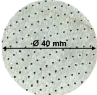
diameter of the wire was 0.534 mm. The depth of the holes was determined by setting the USM tool dis- placement. There were three depths, 2 mm, 3 mm, and 4 mm. The hole density is represented by D, which is defined by the arrangement of the needle pin of the ultrasonic machine (Fig. 1) and calculated with Eq. (1).
(1) The area is not the entire area of the bearing steel.
The circular area that is 40 mm in diameter is taken from the center of the bearing steel and used for the hole density percentage calculation.
There are three kinds of density for each specimen;
there are 2.23% (Fig. 1), 1.77% (Fig. 2), and 1.37%
(Fig. 3) of hole density. The holes diameters are deter- mined by the diameter size of the needle pins that are attached on the horn of the ultrasonic machine. The geometrical parameters of the specimens used in this experiment are shown in Table 1.
2-2. Test set
Fig. 4 depicts the schematic of the machine that is D pin area x number of pin=--- 100%area ×
Fig. 1. 2.23% of holes density.
Fig. 2. 1.77% of holes density.
used for the bearing steel frictional test. Table 2 shows the experimental conditions. In this experiment, there were nine treatments of four specimens except the untextured bearing steel that is just only one. Four rep- lication data for each treatment will be obtained. In total, 36 bearing steel samples and 1 piece of untex- tured bearing steel were used for the experimental test.
The data was recorded by a computer. A sensor (load cell) will measure the surface friction in 60 s with 0.1- s intervals for each variation.
Five variations of load are given to the test specimen and velocities are also given on each loading. This experimental test was done using 24 rpm to 162 rpm and will equal with 0.06 m/s to 0.34 m/s. The sche- matic of the experimental apparatus is shown in Fig. 4.
3. Results and Discussion
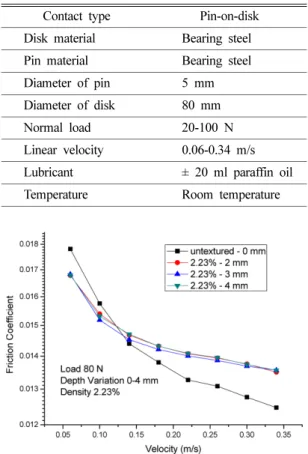
Typical trends of friction coefficient with 80 N of load and 2.23% hole density under different depths and linear velocity are summarized in Fig. 5. On the other hand, Fig. 6 describes the typical trends of fric- tion coefficient with 80 N load and 2 mm depth under different density and linear velocity.
In the other conditions, Fig. 7 and Fig. 8 describe Fig. 3. 1.37% of holes density.
Table 1. Geometrical parameter of bearing steel No Holes density (%) Holes depth(mm) Count
1 2.23
2 3 4
4 4 4
2 1.77
2 3 4
4 4 4
3 1.37
2 3 4
4 4 4
4 Untextured - 1
Fig. 4. Schematic of the experimental apparatus.
Table 2. Test condition
Contact type Pin-on-disk
Disk material Bearing steel
Pin material Bearing steel
Diameter of pin 5 mm
Diameter of disk 80 mm
Normal load 20-100 N
Linear velocity 0.06-0.34 m/s
Lubricant ± 20 ml paraffin oil
Temperature Room temperature
Fig. 5. Friction in variation of velocity and depth.
the correlation between duty numbers with friction coefficient. Variation of depth is shown in Fig. 7 with 80 N of load and 2.23% hole density, while Fig. 8 shows the variation of hole density with 80 N and 2 mm depth. Fig. 7 and Fig. 8 depict correlation duty numbers with a friction coefficient that also describes the lubrication regime between two surface contacts. It is categorized as a mixed lubrication regime based on the Stribeck curve.
Fig. 9 illustrates the typical trends of friction coeffi- cient with 0.34 m/s linear velocity and 2.23% hole density in different conditions of load and depth. Fig- ure 10 illustrates the typical trends of friction coeffi- cient with 0.34 m/s linear velocity and 2 mm depth in different conditions of load and density.
Fig. 5 to 10 show typical trends of the friction coef- ficient for various conditions. Each increment of value
in the horizontal axis direction shows that the trends of friction coefficient have tendencies to decrease.
Variation of velocity significantly affected the fric- tion coefficient. For higher velocities, the lubrication regime is closer to hydrodynamic lubrication. Paraffin oil plays an important factor for support between two surface contacts.
Fig. 6. Friction in variation of velocity and density.
Fig. 7. Friction in variation of duty number and depth.
Fig. 8. Friction in variation of duty number and ensity.
Fig. 9. Friction in variation of load and depth.
Fig. 10. Friction in variation of load and density.
Fig. 5 to 10 depict that untextured line series is crossing another series. For low velocity, the textured bearing steel provides a lower friction coefficient than untextured bearing steel, and for higher velocity, untextured bearing steel provides a better friction coefficient. From this condition, we can conclude that untextured bearing steel reaches a mixed hydrody- namic regime faster than textured bearing steel for higher velocity.
Study is still needed on the higher velocity and load condition to observe the performance of bearing steel to sustain critical loads. In this experiment, we cannot analyze the carrying load capacity. For analyzing car- rying load capacity, the load should be greater than 100 N.
In Fig. 9 and Fig. 10, the friction coefficient on tex- tured bearing steel has no significance difference. For the higher load, the untextured bearing steel provides a lower friction coefficient than textured bearing steel.
Fig. 5 to 10 show the lubrication regime between two surface contacts of bearings. In addition to the analysis of figures, analysis can be performed statisti- cally for emphasizing the correlation and graphical tendencies.
Analysis of variance can be applied to determine a correlation for each parameter. Interaction between hole density and the depth can be performed on 0.05 of á-significance level. For an 80 N load and 0.34 m/s velocity, two-way analysis of variance (ANOVA) with replication revealed no significant correlation between depth and hole density. 2 mm to 4 mm of depth and 1.37%-2.23% of density result in a P-value above 0.05 (α-value). The statistical test results emphasize that density and depth do not affect the friction coefficient in the entire condition. Trend types depict that signif- icant change in the friction coefficient is caused by transformation of the lubrication regime along with velocity variation.
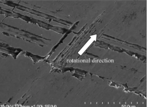
Fig. 11 to Fig. 16 show the surface condition before and after the frictional test. For 0 mm and 2 mm depth and 0% to 2.23% hole density, there is no significant difference. The worn performed by scratch patterns on the bearing steel surface on their rotational direction
itself. For a variation of depth from 0 mm to 4 mm and 1.37% hole density, the scratch patterns are signifi- cantly different depending on the clarity of the scratch patterns. Fig. 11 shows the original pattern of surface bearing steel before the frictional test in 1k magnify- ing and is used for comparing the bearing steel surface condition.
The bearing steel surface is uniform in the image.
The worn performed by scratch patterns on the bear- Fig. 11. Before test (0%-0 mm).
Fig. 12. After test (1.37%-2 mm).
Fig. 13. After test (1.37%-3 mm).
ing steel surface on their rotational direction itself. We can see the condition of bearing steel surface after the frictional test from the figure: worn patterns are clearly crossing the original patterns of bearing steel surface and are shown with an arrow.
5. Conclusions
In this study was performed that no correlation
between depth and hole density on the bearing steel surface to friction coefficient. Graphical trends show that the friction coefficient decreases depending on load and velocity. This describes a variation of veloc- ity causing effect in the transformation of lubrication regime. Textured bearing steel provides a low friction coefficient in low velocity than untextured bearing steel, and a high friction coefficient in higher velocity.
In other words, the bearing steel with 2 mm depth variation has a lower friction coefficient in 80 N of load and 0.34 m/s of velocity than the other textured bearing steel in the entirety of hole density. The bear- ing steel was resulting in 0.0130 of friction coefficient at 1.37% hole density, 0.0129 of friction coefficient at 1.77% hole density, and 0.0135 of friction coefficient at 2.23% hole density. The lowest friction coefficient is provided by 1.77% hole density at a 2 mm depth and is categorized in the mixed lubrication regime.
Distribution of holes is a very important factor. It effecting to the contact surface on frictional test exper- iment.
References
[1] Egashira, K., Kumagai, R., Okina, R., Yamaguchi, K., Ota, M., “Drilling of Microholes Down to 10 µm in Diameter Using Ultrasonic Grinding”, Precision Engi- neering, 38, pp 605-610, 2014.
[2] Schorderet, A., Deghilage, E., Agbeviade, K., “Tool Type and Hole Diameter Influence in Deep Ultra- sonic Driling of Micro-holes in Glass”, Proceed- ings of the CIRP, 6, pp. 565-570, 2013.
[3] Jacobson, B., “The Stribeck Memorial Lecture”, Tri- bology International, 36, pp. 781-789, 2003.
[4] Woydt, M., Wäsche, R., “The History of the Stribeck Curve and Ball Bearig Steels: The Role of Adolf Martens”, Wear, 268, pp. 1542-1546, 2010.
[5] Cho, M. H., Park, S. “Micro CNC Sufrace Texturing on Polyoxymethylene (POM) and its Tribological Per- formance in Lubricated Sliding”, Tribology International, 44, pp. 859-867, 2011.
[6] Tang, W., Zhou, Y., Zhu, H., Yang, H., “The Effect of Surface Texturing on Reducing The Friction and Wear of Steel Under Lubricated Sliding Contact,”
Applied Surface Science, 273, pp. 199-204, 2013.
[7] Scaraggi, M., Mezzapesa, F. P., Carbone, G., Ancona, A., Sorgente, D., Lugara, P. M., “Minimize Friction of Lubricated Laser-Microtextured-Surface by Tun- Fig. 14. After test (1.37%-4 mm).
Fig. 15. After test (1.77%-2 mm).
Fig. 16. After test (2.23%-2 mm).
ing Microholes Depth”, Tribology International, 75, pp. 123-127, 2014.
[8] Wakuda, M., Yamauchi, Y., Kanzaki, S., Yasuda, Y.,
“Effect of Surface Texturing on Friction Reduction between Ceramic and Steel Materials Under Lubri- cated Sliding Contact”, Wear, 254, pp. 356-363, 2003.