3D 토공 BIM 시스템 데이터베이스 구축을 위한 속성 데이터 관리
Attribute Data Management for Developing the Database of a 3D Earthwork BIM System
문성우
1), 서종원
2)Sungwoo Moon
1)・ Jongwon Seo
2)Received October 10, 2016; Received December 3, 2016 / Accepted December 4, 2016
ABSTRACT: A Building Information Model (BIM) is an attempt to simulate the process of building structures in a three-dimensional (3D) digital space. While the technology is usually applied to structured buildings, bridges, and underground facilities, it is rarely applied to an unstructured environment of earthwork operations. If a BIM is used for earthworks, the 3D simulation can be used for construction equipment guidance and earthwork management. This paper presents a real-time, 3D earthwork BIM that provides a 3D graphical simulation of excavators in conjunction with geographic modeling. Developing a real-time, 3D earthwork BIM requires handling a variety of factors, such as geographical information and vehicular movement. This paper mainly focuses on the management of these attributes and provides a database design for storing and retrieving data. In an example application, a prototype of the 3D earthwork BIM is presented to understand what it would provide when used during earthwork operations at a construction site.
KEYWORDS: Construction equipment, BIM, 3D earthwork BIM, earthwork construction, ground terrain modeling, equipment modeling 키워드: 건설장비, BIM, 3D 토공 BIM, 토공작업, 지형형상 모델링, 건설장비 모델링
1)정회원, 부산대학교 사회환경시스템공학과 교수, [email protected]
2)정회원, 한양대학교 건설환경공학과 교수 ([email protected]) (교신저자)
DOI: https://doi.org/10.13161/kibim.2016.6.4.027
1. Introduction
1.1 Background
A Building Information Model (BIM) provides a three- dimensional (3D) graphical environment in which constructed facilities are modeled. This modeling technique offers graphical simulation views as well as data management tools throughout a construction project. Connected to a database, the BIM can be used for managing the information on the time and cost of construction.
The BIM is used to provide visual information on a structure in a 3D graphical simulation. Construction workers can understand design requirements by viewing the 3D model.
This inspection function can give the construction workers prior knowledge of what needs to be accomplished before they assign tasks. The visual inspection function also helps
identify the design conflicts when construction parts interfere with each other.
The BIM can be also used for scheduling and cost control.
As the construction progresses, the BIM can show the change in the structural shape in relation to time. The BIM components are able to schedule, and they can show the current schedule status. The BIM components also have attributes for cost control, and they can show the budget status.
This information can be saved and reused throughout the project’s life cycle (Dakhil and Alshawi, 2014). The BIM approach is widely accepted in the construction industry and has become common practice. In this context, Azhar (2011) stated that the BIM is one of the most promising developments in the architecture, engineering, and construction (AEC) industries in recent years. However, the BIM is mostly applied to prestructured facilities, such as office buildings,
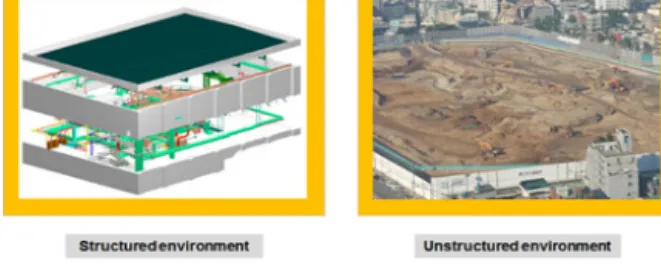
Figure 1. Unstructured environment for the 3D earthwork BIM
industry facilities, and bridges. The predefined structures ofthese entities facilitate a modeling the design scheme; con- sequently, applications concentrate on predefined structures.
Although the BIM is widely practiced in prestructured environments, it is also applicable to civil infrastructures such as roads, rails, and ports. Kim et al. (2014) argued that these types of civil infrastructures have a wider target range compared to the prestructured environments. Kim (2011) also argued that the civil infrastructures have to interact with the natural conditions and that these constraints impose many obstacles when applying the BIM technology.
The 3D earthwork BIM is an attempt to apply a 3D graphical tool to an unstructured environment of earthwork operations. Unlike for the prestructured environments, the earthwork operation is executed in natural conditions. The 3D earthwork BIM models the terrain and the construction equipment at the construction site.
Since the process of the earthwork operation is not predefined, this approach of 3D earthwork BIM requires a new technique compared to the conventional BIM. When applied to the earthwork operation, the BIM technology simulates the change of the terrain and then simulates the movement of the construction equipment at the construction site. This combined effort can result in the 3D earthwork BIM.
This paper presents a real-time, 3D earthwork BIM that provides a 3D graphical simulation of excavators in con- junction with geographic modeling. Developing such a BIM requires handling a variety of attributes, including geographic information and vehicular movement. This paper mainly focuses on the management of these attributes and provides a database design for storing and retrieving data. In an example application, a prototype of the 3D earthwork BIM is presented to understand what it would provide when used during earthwork operations at a construction site.
1.2 Structured vs. Unstructured
The term structured means that, given the information on future events, the construction manager sets up the sequence and timing of occurrences before construction begins. In construction, the BIM is usually built on predefined conditions.
For example, the plans of buildings, bridges, and underground facilities have information on dimensions, materials, and quantities of structural components (Figure 1). Using this
information, the construction manager can schedule the sequencing and timing of construction activities (Sabahi, 2012) to erect the structural components and plan resource assignments.
The term unstructured means that the construction manager cannot set up the sequence and timing of occurrences in the absence of information on future events. Unlike the traditional BIM, the 3D earthwork BIM is built on undefined conditions.
Civil infrastructures, such as roads, rails, and ports, are usually executed from unstructured environments. As Kim et al. (2014) argued, these types of civil infrastructures have more variables and should handle a wider target range than the prestructured environments.
For example, the design of earthwork describes the final outline of terrain shapes. Since the information is limited, the construction manager cannot schedule the sequence and timing of construction activities for the earthwork operations.
1.3 Research Methodology
The 3D earthwork BIM was built to simulate the dynamic changes of terrain shapes and equipment configurations during earthwork operations. This unstructured nature makes it necessary to apply sensory devices, position data for configuration, and position tracking of construction equipment.
The changes in the ground terrain should be constantly updated to show the status of the excavation in real time.
That is, the 3D earthwork BIM requires a combination of geographic modeling and configuration modeling to model the undefined earthwork operations.
Figure 2 shows the five steps in the research procedure for modeling the earthwork operation at a construction site.
First, the user requirements for the 3D earthwork BIM are evaluated from the perspectives of the construction manager
Figure 2. Research procedure
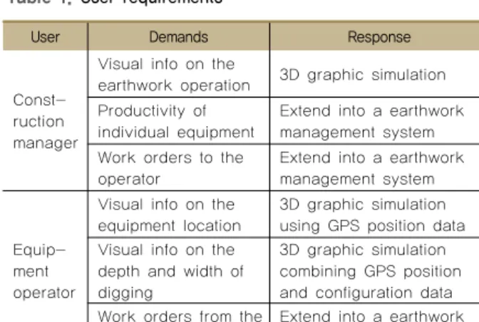
Table 1. User requirements
User Demands Response
Const- ruction manager
Visual info on the
earthwork operation 3D graphic simulation Productivity of
individual equipment Extend into a earthwork management system Work orders to the
operator Extend into a earthwork management system
Equip- ment operator
Visual info on the
equipment location 3D graphic simulation using GPS position data Visual info on the
depth and width of digging
3D graphic simulation combining GPS position and configuration data Work orders from the
construction manager Extend into a earthwork management system
and the equipment operator. Second, the attributes are analyzed for developing a database for the 3D earthwork BIM. Third, a database is developed for storing and retrieving attribute data when running the 3D earthwork BIM system.
Fourth, the 3D earthwork BIM prototyping is used to model the change of the ground terrain and the movement of construction equipment at the construction site. The geographic modeling simulates the change of terrain shapes, whereas the excavator configuration modeling simulates the equipment configuration. These two parts of the modeling are combined to provide a 3D graphic simulation environment. Finally, the prototype is built based on the geographical modeling and equipment configuration modeling to test functionality.
2. Literature Review
The application of the BIM technology is not frequently found in the area of earthwork operations. However, the 3D modeling technique is often used as a machine guidance tool. The machine guidance system is an application that provides earthwork-related information to the equipment operator. The system is usually mounted in the cabin of construction equipment, assisting the equipment operator.
Commercial simulation products are available in the market (Laica-Geosystems, 2016; Prolec, 2016; TopCon, 2016; Trimble, 2016) and provide machine guidance functions in 2D or 3D spaces. These commercial products provide visual and numerical information that is useful for the operation of construction equipment during the earthwork operation.
These devices help the equipment operator in digging and cutting ground surfaces, and they remove the need for surveyors. However, these machine guidance tools are not as effective as a BIM; they mostly use 3D models of con- struction equipment as a visual aid.
Although the concept of a BIM is relatively new in the area
of civil engineering and design, Jo et al. (2012) have tried to apply a BIM in designing earthwork for the development of an industry park. The authors built a BIM for the entire body of the industry park in a 3D graphical model using digital maps.
The BIM included details such as a vehicle road, utility pipe, drainage, geographical terrain, and the factory site.
The BIM generated information on the amount of cutting and filling of earthwork. The authors tried to apply the BIM together with the existing design tools for structural analysis and estimation, suggested the need to integrate a variety of design tools with the BIM in the design stage. As the authors suggested, the BIM can be applied throughout the cyclical design process of construction.
Jo et al. (2012) tried to apply the BIM technology to improve design effectiveness. Designers can benefit from the functions that a BIM provides. However, when the concept of a BIM is applied to the simulation function, the functionality of the 3D graphical simulation can be utilized to not only guide equipment operators but also provide managerial functions.
This technology can be further extended to the fleet management of construction vehicles (Regan, Mahmassani and Jaillet, 2014). Then, the individual effort of the 3D earthwork BIM can be further enhanced to include a variety of construction vehicles that are deployed during the earthwork operation.
3. Requirements of the 3D Earthwork BIM
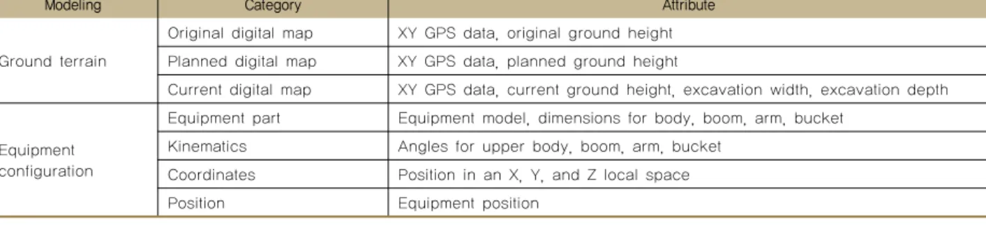
The 3D earthwork BIM provides benefits both to the construction manager and the equipment operator (Table 1).Table 2. Attributes for developing a 3D earthwork BIM system
Modeling Category Attribute
Ground terrain
Original digital map XY GPS data, original ground height Planned digital map XY GPS data, planned ground height
Current digital map XY GPS data, current ground height, excavation width, excavation depth
Equipment configuration
Equipment part Equipment model, dimensions for body, boom, arm, bucket Kinematics Angles for upper body, boom, arm, bucket
Coordinates Position in an X, Y, and Z local space
Position Equipment position
The construction manager can use the BIM to determine whether the equipment is being operated properly at the right location. When extended into an earthwork management system, the construction manager can use the BIM to measure productivity and issue work orders to the equipment operator.
The equipment operator can use the BIM to understand the task during the earthwork operation. The 3D earthwork BIM can generate information to the equipment operator, visual information on the equipment location, and the depth and width of digging. When extended into an earthwork management system, the equipment operator can get work orders from the BIM.
In addition, the BIM can be integrated into machine control.
Since machine control technology has been developed to enhance the performance of excavators (Azhar, 2011), the BIM technology can be integrated with the machine control to enhance the effectiveness of equipment control.
This paper mainly focuses on 3D graphical simulation by integrating the movement of construction equipment with the change of ground terrain at the construction site. The earthwork management system remains for future study.
The 3D earthwork BIM provides a real-time, 3D graphical simulation of earthwork. During earthwork, the BIM simulates the movement of construction equipment and the change in the ground terrain.
4. Modeling Attributes
Since the earthwork operation handles the excavation of ground, this BIM technology should simulate not only the equipment configuration but also the terrain. This graphical environment is developed by applying geographic modeling and equipment configuration modeling. Geographic modeling
describes the change to the terrain at the construction site.
The equipment configuration modeling describes the change in equipment movement during earthwork.
Table 2 shows the key attributes that are required in prototyping the earthwork 3D BIM environment. In the table, the modeling is divided into 1) the ground terrain and 2) equipment configuration. In modeling the ground terrain, the original digital map has the attributes of XY GPS data and original ground height to show the original ground height before excavation has started.
The planned digital map has the attributes of XY GPS data and planned ground height to show the planned ground height of the construction design. The current digital map has the attributes of XY GPS data, current ground height, excavation width, and excavation depth to show the actual ground height and shape after excavation has been completed.
The planned digital map has the attributes of XY GPS data and planned ground height to show the planned ground height of the construction design. The current digital map has the attributes of XY GPS data, current ground height, excavation width, and excavation depth to show the actual ground height and shape after excavation has been completed.
In modeling the equipment configuration, the equipment part has attributes to show the configuration of the con- struction equipment. The kinematics show the configuration of the construction equipment, and the coordinates show the X, Y, and Z space for construction equipment and the current position of the excavator. These attributes are stored in a database and are updated constantly during the simulation of the 3D earthwork BIM.
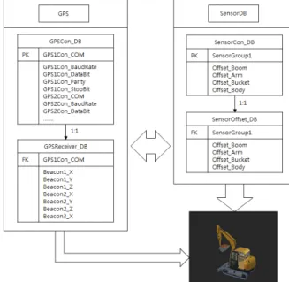
Figure 4. Structure of the entity relation diagram
5. Database Design
5.1 Sequence Diagram
The sequence diagram shows the flow of data or actions of objects in a sequential order in a simulated environment.
Figure 3 shows a sequence diagram that represents the data flow in the 3D earthwork BIM.
In the sequence diagram, the objects include 1) the equipment operator, 2) the excavator, 3) the sensory device, 4) the GPS device, 5) the 3D simulation environment, and 6) the database. The equipment operator is in charge of the overall control of the 3D earthwork BIM. The excavator is the subject of the 3D graphical simulation. The sensory device generates the angular values for equipment configuration.
The GPS device generates the current location of the construction equipment. The GPS device also generates the orientation of the construction equipment. The 3D simulated environment runs a graphical simulation. The database stores the attributes data of the 3D earthwork BIM.
The sequence diagram shows that the 3D earthwork BIM is a continuous flow of attribute data during which earthwork- related data are generated and stored. The data are generated in each step of the earthwork process and are retrieved to generate the movement of construction equipment in the 3D graphical environment.
Figure 3. Sequence diagram
5.2 Entity Relation Diagram
During the earthwork operation, the attribute data should be effectively controlled in a database structure. The Entity-Relation Diagram (ERD) depicts the structure of the data
and provides a preset structure of database management.
The ERD shows the structure of tables and their relations in a database.
An ERD was built to designate the relation of attribute tables for the 3D earthwork BIM. The relational structure simplifies the database design and provides an efficient control mechanism in the database management. Figure 4 shows the simple structure of the ERD that has been developed for the 3D earthwork BIM. In the ERD, each entity has attributes of its own and has 1:N relations.
The ground terrain section has the two tables of GPSCon_DB and GPSReceiver_DB. GPSCon_DB stores attribute data that are required for setting up the protocols for the two GPS devices of GPS1Con and GPS2Con. GPSReceiver_DB stores the attribute data for the geographical location of the con- struction equipment in the XYZ coordinate.
In addition, the construction equipment section has the stores the attribute data that are generated using sensors attached to the bodies of the construction equipment.
SensorOffset_DB stores the attribute data that shows the configurations of the construction equipment.
The GPSCon_DB table has a primary key of GPS1Con_COM, which is used as a foreign key in the GPSReceiver_DB table.
The SensorCon_DB table also has a primary key of Sensor- Group1, which is used as a foreign key in the SensorOffset_DB table. These tables have a 1:1 relation.
(a) Position for sensor installation
(b) Actual image of sensor installation Figure 6. Installation of sensors for an excavator 5.3 Database Development
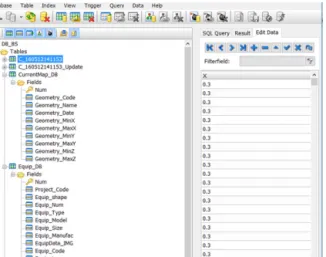
Figure 5 shows the database that has been developed using the Microsoft SQL Server Management Studio program.
CurrentMap_DB contains the status attributes of the terrain, and Equip_DB contains the status attributes of the construction equipment. These attributes are required to control changes in the terrain and the movement of construction equipment and are updated to obtain the status of the earthwork operation. The data retrieved from the database are used to create graphic simulations in a 3D earthwork BIM environment, which constantly shows the movement of construction equipment and the changes in terrain.
Figure 5. Design of a database
A table for equipment libraries needs to be prepared to store attribute required to configure individual construction equipment. This table should contain attributes describing the various types of construction equipment, including the sizes of sectional parts; for example, an excavator is made up of the excavator body, boom, arm, and bucket, which was the prototype developed in this study. All configuration attributes for all construction equipment used in a prototype should be stored in the table for use in 3D graphic simulations.
6. Prototyping
Prototyping a 3D earthwork BIM environment is a dynamic process that requires modeling of terrain and equipment configurations, which should be combined to simulate excavation operations. Current fleet management systems are based on
2D or 3D models. The 2D-based system uses 2D section images to indicate requirements for equipment control, while the 3D-based system describes the movement of construction equipment in the 3D digital spaces of construction sites.
Here, construction equipment is indicated only by movement in a preset space. In contrast, 3D earthwork BIM environments actually model construction equipment and terrain to scale and provides more flexible functions for describing the requirements of equipment control.
During 3D simulation, the terrain is modeled by manipulating digital maps for original, planned, and current terrains. The digital map data are stored in and retrieved from the database and obtained primarily from sensory values and GPS data.
The sensory values are used to estimate excavator con- figurations, while GPS positioning data are used to monitor an excavator’s position and calculate its orientation at a construction site (Figure 6).
This is accomplished by sensors installed on excavator components, such as the boom, arm, and bucket, to measure changes in the angles between the components (Figure 3).
Two GPS devices are installed on the body of the excavator to measure its position in the XYZ space of a construction site. The orientation of the excavator is estimated using the
Figure 7. Prototype images of the 3D earthwork BIM
Figure 8. Prototype images of the 3D earthwork BIM
difference between these positions measured by the GPS device.A database has also been developed for data storage to save configuration and position data. Before starting an excavation operation, the original map is loaded into the database. During excavation, the database is updated to provide the excavation’s status. The log of actual data is retrieved and analyzed after excavation to understand operational performance.
3D graphic simulation requires detailed modeling of equipment components. As discussed in the previous section of this paper, an excavator is made up of the excavator body, boom, arm, and bucket. Figure 7 shows the images of an excavator’s body, boom, arm, and bucket. During the 3D graphical simulation, these equipment components combined to show the movement of equipment configuration.
A database has also been developed for data storage to save configuration and position data. Before starting an excavation operation, the original map is loaded into the database. During excavation, the database is updated to provide the excavation’s status. The log of actual data is retrieved and analyzed after excavation to understand operational performance.
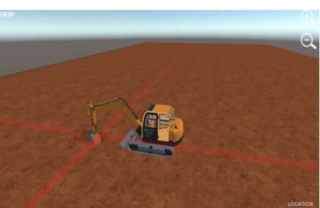
Figure 8 shows the prototype images of the earthwork
operation. The 3D earthwork BIM system is actually applied in the field, and graphic representations are compared to the actual movement of construction equipment. The terrain changes after digging in real time during excavation. The geographical data for the original, planned, and actual terrains are constantly updated to show the changes during simulation. The equipment configuration is also constantly updated to show the movement of excavators in relation to the dump truck. This combined effort results in a graphic simulation in a 3D space. Overall, the actual movement of the excavator at the construction site matched the graphic movement of the excavator in the 3D digital space.
7. Conclusion
The 3D earthwork BIM applies the concept of the BIM to an earthwork operation. The prototype of the 3D earthwork BIM environment has been under development in a lab setting. As a prerequisite to prototyping, the attributes for the 3D earthwork BIM have been identified and entered in a database. The database stores and updates these attributes to provide information that is required for the 3D graphical simulation. Using this information, the ground shape is updated, and the equipment configuration is represented in a 3D space.
Using an indoor testbed with controlled conditions, the capability of the 3D simulation has been tested. When the prototype is developed, the 3D earthwork BIM environment will be applied to an actual earthwork operation at a construction site. The 3D earthwork BIM can be used to guide the equipment operators during excavation, and the operators can get graphical views of the excavation and assist equipment operators.
When integrated with a project management information system, the 3D earthwork BIM can be used to generate information on the status of earthwork. This information can be used for updating the amount of finished excavation, amount of remaining excavation, idle time, working time, number of transports needed for the disposal of excavated soil, and more. The application of BIM technology to earthwork operations can benefit the construction manager.
The 3D earthwork BIM environment can also be used to measure the productivity of an earthwork operation and be a training tool for novice equipment operations.
Acknowledgments
This research was supported by a grant (16SCIPB07969003) from the Smart Civil Infrastructure Research Program funded by the Ministry of Land, Infrastructure, and Transport of the Government of Korea and the Korea Agency for Infrastructure Technology Advancement.
References
Azhar, S. (2011). Building Information Modeling (BIM): Trends, Benefits, Risks, and Challenges for the AEC Industry, Leadership and Management in Engineering, 11(3), pp.
241-252.
Dakhil, A. and Alshawi, M. (2014). Building Information Modelling Benefits-Maturity Relationship from Client Perspective, Information and Knowledge Management, 4(9), pp. 8-16.
Jo, J. J., Ju, Y. D., Kim, S. M., and Seo, H. J. (2012).
Applications and Future Study of Earthwork BIM, Proceedings of Korea Institute of Building Information Modeling, pp. 71-72.
Kim, M. J., Lee, K. H., Kwon, S. H., P, S. I., and Lee, S. C.
(2014). BIM Application Case Study of Civil Infrastructure Industry, Proceedings of The Korean Society for Railway.
Kim, Y. H. (2011). BIM for the Public Infrastructure Facilities, KIBIM Magazine, pp. 27-30.
Laica-Geosystems. iCON iXE3 - 3D System, http://leica- geosystems.com/products/machine-control-systems/
excavator/leica-icon-ixe3---3d-system, (Jul. 5, 2016).
Prolec. Machine control: ProGrade, http://www.prolec.co.uk/
en/what-we-do/products/prograde, (Jul. 5, 2016).
Regan, A., Mahmassani, H. and Jaillet, P. (2014). Evaluation of Dynamic Fleet Management Systems: Simulation Framework, Journal of the Transportation Research Board (1645), Transportation Research Board of the National Academies, Washington, D.C., DOI: 10.3141/1645-22.
Sabahi, P. (2012). Speeding Up the Process of Modeling Temporary Structures in a Building Information Model Using Predefined Families, Master's thesis, Texas A&M, College Station, TX.
Trimble. Grade control for excavators, http://construction.trimble.com/
products/machine-control/grade-control-for-excavat ors, (Jul. 5, 2016).
TopCon. Mass excavation, http://www.topconpositioning.
com/construction/mass-excavation, (Jul. 5, 2016).