I. Introduction
Recently, there has been tendency that more and more patient of dental clinic want dental implant and need restoration of fully or partial edentulism by dental implant. The use of dental implants for replacing missing teeth and other oral structures has been increasing rapidly throughout the world, with functional 5-year success rates of 90% or higher reported1-6. For the success of dental implant, pre- operative diagnostic step is critical step and preci- sion of diagnostic method or tool is very important.
Therefore, many variable diagnostic method has been introduced and used.
Among these, the most widespread and comfort- able diagnostic method is radiography, that is, panoramic radiography. The advantages of panoramic radiography include visualization of many anatomic features, low cost, and availability7,8
and most surgeon of dental implant use only panoramic radiography with surgical stent or metal ball9. But panoramic radiography has inherent limi- tation; magnification and distortion. Panoramic views produce a variable inherent magnification, distortion, typically 20% to 30%. Although magnifi- cation in the vertical plane is relatively stable, magni- fication in the horizontal plane is highly variable, depending on location in the arch, distance, and position of object with respect to the focal trough and positioning of the patient. In addition, longitudi- nal assessment was not possible because of the diffi- culty in reproducing the exact patient position with- in the panoramic devide7,8,10. Thus many clinician insist on necessity of CT/MPR(Computed Tomography/Multiplanar reformatting) for some patient who has unique anatomical characteristics;
resorbed ridge, concavity of ridge etc. and who need implant in critical site that has proximity to
The Affecting Factor to Magnification Ratio from Alveolar Crest To Inferior Mandibular Canal in Diagnosis of Implant
Site of Mandibular Molar Region with Panoramic Radiography
Jae-Jin Jung, Sang-Mook Choi, Yong-Moo Lee, Young Ku, Chong-Pyoung Chung, Soo-Boo Han, In-Chul Rhyu
Department of Periodontology, College of Dentistry, Seoul National University
대한치주과학회지 : Vol. 31, No. 4, 2001
This study supported by Grant No. 219962440 from the Seoul National University Hospital Research Fund
vital organ; maxillary sinus, nasopalatine canal, nasal cavity, inferior alveolar canal, mental foramen11-22. And CT/MPR is essential for some clinician because the success rate of the seasoned clinician may not be matched initially by others with less experience10. Thus the information provided by cross-sectional imaging may be of more importance to some practitioners than to others. But CT/MPR is not common diagnostic method because of eco- nomic problem23and dose of radiation24-27, so far
Therefore, it is necessary for surgeon of dental implant to utilize CT/MPR imformation and to infer CT/MPR image with panoramic radiography in situ- ation that CT/MPR is not available. In order that it is possible, we need to know how much difference panoramic radiography and CT/MPR make and what makes the difference much or less.
This study was designed to know magnification ratio of panoramic radiography to CT/MPR and dif- ference between panoramic radiographic value and CT/MPR value and designed to inspect the anatomy of mandible(angulation of long axis of mandible, bucco-lingual width of mandible, site of inferior mandibular canal) affect magnification ratio of panoramic radiography to CT/MPR with the patients who visited Seoul National University Hospital for dental implant surgery in mandibular molar area.
II. Materials and Methods
1. Subject selectionWe selected 15 patients who visited Seoul National University Hospital for dental implant surgery from January. 1997 to April. 2000.
Among patient who had partial edentulism, we selected the patient who needed restoration of mandibular molar area that did not need to receive bone graft or membrane surgery and in that running
of inferior mandibular canal was visible. The mandibular canal is not always well-visualized radi- ographically, in part because of the lack of cortical outline in some jaws28.
Included site was 32 site and subject was consist- ed of 8 male plus 7 female.
2. Preoperative preparation
Selected patient had preoperative diagnostic base(preoperative panoramic radiography, CT/MPR). In most patient, CT/MPR image was with diagnostic stent but panoramic radiography with diagnostic stent was rare and most diagnostic stent was not presented and changed to surgical stent.
For the exact comparison of panoramic radiogra- phy and CT/MPR, common site(exact site) for implant installation needed to be compared and magnification ratio of panoramic radiography need- ed to be known. Therefore, postoperative panoram- ic radiography and CT/MPR was necessary and magnification radio of panoramic radiography was calculated with metal ball.
3. Postoperative preparation
After first or second surgery, 15 patient was recalled for postoperative panoramic radiography and CT/MPR taking. Panoramic radiography was taken with 3mm or 5mm metal ball in the implant installation site under common panorama taking condition. Panoramic radiography machin were Cranex 3+ Ceph (Soredex orion corp, Helsinki, Finland), Auto 2000 (Asahi, Kyoto, Japan), and Orthophos (Siemens, Germany).
CT machin was IQ (Picker, USA) and CT/MPR was ToothPix (Picker, USA). CT/MPR image was obtained under 130 kV, 105mA, 2mm thickness and 1mm interval and with same reformatting condition
of preoperative CT/MPR as soon as possible.
4. Measurements
(1) In panoramic radiography, vertical length of metal ball was measured to 0.1mm scale(m1)
and length of metal ball in direction of implant installation(with same angulation) was too measured to 0.1mm scale(m2).(Figure 1) (2) In panoramic radiography, length from alveo-
lar crest to superior border of inferior mandibular canal (c-c) was measured, this Figure 1. Measuring magnification ratio of
panoramic radiography with metal ball
Figure 2. Length from alveolar crest to superior border of inferior mandibular canal (c-c)
Figure 3. Anatomical measurement in CT/MPR
measurement was obtained with same angula- tion of implant installation and to 0.1mm scale.(Figure 2)
(3) In CT/MPR image,(Figure 3)
① length from alveolar crest to superior border of inferior mandibular canal (c-c)
② horizontal length from lingual border of mandibular bone to inferior mandibular canal (c-l)
③ horizontal length from implant fixture to inferi- or mandibular canal (c-f)
④ bucco-lingual width of mandibular bone (b-l)
⑤ angulation of long axis of mandibular bone (angle) were measured
All measurements were obtained twice with the interval of two weeks to 0.1mm scale by same radi- ologist and with Dial Caliper (Mitutoyo, Japan). All measurements were obtained by only one radiolo- gist because large interobserver differences in identi- fying the mandibular canal have been reported29
5. Statistics
(1) Average difference between panoramic radi- ography value and CT/MPR value ( magnifica- tion ratio of panoramic radiography was
obtained and average value was adopted) was obtained.
(2) After magnification ratio of panoramic radiog- raphy to CT/MPR was obtained, we analized whether this value had correlation with anatomical measurements(c-l, c-f, b-l, angle) in CT/MPR image by Pearson's correlation coeffi- cient test.
III. Results
1. Magnification ratio of panoramic radiography Average vertical magnification ratio of panoramic radiography was 129%. This value was obtained by measuring vertical length of metal ball in panoramic radiography. This value, 129%, was greater than commonly used 125%. When we install implants in mandibular molar site, installation direction is not always perpendicular to horizontal plane. Therefore, magnification ratio of panoramic radiography with the same angulation of implant installation is more meaningful to clinician. In measuring of length of metal ball with the same angulation of implant installation, average magnification ratio of panoramic radiography was 132%. This Figure 4. Magnification ratio of
panoramic radiography
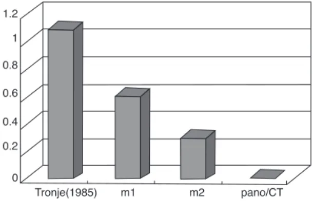
Figure 5. Average difference between panoramic radiography value and CT/MPR value
value was greater than 129%, vertical magnifi- cation ratio of panoramic radiography. In the assumption that CT/MPR has 1:1 magnification ratio, we calculated the magnification ratio of length from alveolar crest to superior border of inferior mandibular canal in panoramic radiog- raphy. Average magnification ratio of panoram- ic radiography to CT/MPR was 135%, the great- est value.(Figure 4)
2. Average difference between panoramic radiog- raphy value and CT/MPR value After measuring of length from alveolar crest to superior border of inferior mandibular canal(c-c) in panoramic radiography and in the CT/MPR(c-c), respec- tively, 125%30, vertical magnification ratio, 129%, and magnification ratio with same angu- lation of implant installation, 132% were used to obtained length from alveolar crest to superi- or border of inferior mandibular canal in panoramic radiography. And average differ- ence between panoramic radiography value and CT/MPR value was calculated. In 125%, the difference was 1.1mm, in 129%, 0.6mm.
and in 132%, 0.3mm.(Figure 5)
3. Correlation between anatomical measurement
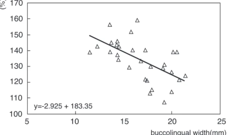
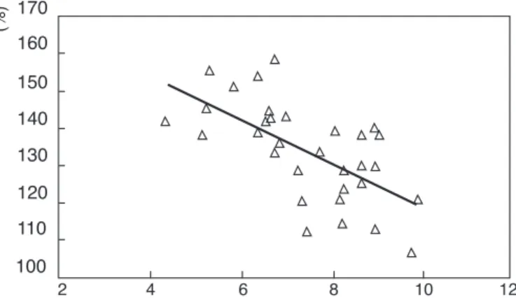
and magnification ratio of panoramic radiogra- phy to CT/MPR In CT/MPR image, bucco-lin- gual width of mandibular bone(b-l) had signifi- cant negative correlation with average magnifi- cation ratio of panoramic radiography to CT/MPR (r=-0.604, p< 0.05).(Figure 6) This means that the greater bucco-lingual width of mandible is, the smaller average magnification ratio of panoramic radiography is. and patient with mandible of small bucco-lingual width has the tendency to high magnification ratio in panoramic radiography. The horizontal length from lingual border of mandible to inferior mandibular canal(c-l) had significant negative correlation with average magnification ratio of panoramic radiography to CT/MPR (r=-0.640, p<0.05).(Figure 7) The horizontal length from implant fixture to inferior mandibular canal(c-f) had significant negative correlation with aver- age magnification ratio of panoramic radiogra- phy to CT/MPR (r=-0.515, p< 0.05).(Figure 8) This means that patient with more lingual-sited inferior mandibular canal has the tendency to high magnification ratio in panoramic radiogra- phy. Finally, Average magnification ratio of
Figure 6. Correlation between bucco-lingual width of mandibular bone(b-l) and magnification ratio of panoramic radiography
Figure 9. Correlation between angle of long axis of mandibular bone and magnification ratio of panoramic radiography
Figure 8. Correlation between the horizontal length from implant fixture to inferior mandibular canal(c-f) and magnification ratio of panoramic radiography Figure 7. Correlation between the horizontal length from lingual border of mandible to
inferior mandibular canal(c-l) and magnification ratio of panoramic radiography
panoramic radiography to CT/MPR had signifi- cant positive correlation with angulation of long axis of mandible (r=0.446, p<
0.05).(Figure 9) This means that patient with mandible of high angle has the tendency to high magnification ratio in panoramic radiogra- phy and that the more perpendicular to hori- zontal plane the mandible is, the higher the magnification ratio of panoramic radiography to CT/MPR is.
IV. Discussion
In 1985, Tronje and Welander et al30. proposed the 125% as magnification ratio of panoramic radi- ography and after then, many surgeon of dental implant who use the panoramic radiography as implant diagnostic method has utilized 125% magni- fication ratio without doubt.
But, in this study, when we calculated the vertical magnification ratio of panoramic radiography with metal ball, average 129%, the greater value was obtained and when we measured the magnification ratio with same angulation of implant installation, average 132% magnification ratio was obtained. this value was greater than vertical magnification ratio, 129%. Therefore, though variation of magnification ratio with site was not considered in this study, if this is considered, the magnification ratio of panoramic radiography is very variable with site and with angulation. When we install implants in mandibular molar site, installation direction is not always perpendicular to horizontal plane.
Therefore, magnification ratio of panoramic radiog- raphy with the same angulation of implant installa- tion is more meaningful to clinician. If all are to be considered, 130% greater than 125% was reasonable for magnification ratio of panoramic radiography as was proposed by German Gomez-Roman et al. in
199931. Average magnification ratio of panoramic radiography to CT/MPR was 135%, this was too con- firm that 125% magnification ratio was not proper.
In this study, with 129% magnification ratio, aver- age difference between panoramic radiography value(c-c) and CT/MPR value(c-c) was 0.6mm and with 132% magnification ratio, 0.3mm. this may be interpreted in two way, One is that real magnifica- tion ratio of panoramic radiography was greater than 129% or 132%. The other is that CT/MPR image underestimated the real image. In spite of the effort that sectioning angle was to be parallel to implant installation in the CT/MPR, it was possible that sec- tion view was not parallel to implant and therefore underestimation in CT/MPR was possible to be.
Accoding to some author, for CT imaging, the refer- ring dentist should communicate thoroughly with the radiologist and ensure that the patient is posi- tioned appropriately(0 degree gantry angle), that the scan plane is parallel to the occlusal plane10. This ideal condition was not possible in some patient and all the implant fixtures in one patient were not always parallel to each other.
When we calculated magnification ratio of panoramic radiography to CT/MPR, Gold-standard was CT/MPR image. Although CT/MPR image is regarded to have 1;1 magnification, ±1mm differ- ence is commonly accepted. In 1989, Klinge et al32. proposed that 94% of CT/MPR measurement and only 17% of panoramic radiography measurement was within ±1mm. The assumption that CT/MPR had 1;1 magnification ratio was reasonable but was not always acceptable for some variables.
Other factor that affected measuring difference was artifacts of postoperative CT/MPR image by metallic component and another factor was that bor- der of alveolar crest was not clear because of metal- lic component. these made the some measurement impossible and some subjects excluded.
According to the results obtained by this study, the magnification ratio of panoramic radiography to CT/MPR is greater as the mandibular bone has greater angle to horizontal plane and as the inferior mandibular canal is more lingual site. this was statis- tically significant. In some aspects, this results was opposite to principle of panoramic radiography tak- ing that projection geometry causes images of lin- gual structure to be cast superiorly to those of facial- ly-located structures, thus distorting the relative rela- tionship of objects in the vertical plane33. Therefore, the reasonable explanation of this results is remained to be studied. And it is too considered that this study was designed with small sample size and variation of the subjects was not great.
Therefore, In order that the results of this study is to be meaningful to clinician of implant dentistry, the study with large sample size and with well con- trolled condition is necessary and the results in this study must be confirmed by such studies.
V. Conclusion
1. Average vertical magnification ratio of panoram- ic radiography with metal ball was 129% and average magnification ratio of panoramic radi- ography with metal ball in the same angulation of implant installation was 132%.
2. Average magnification ratio of panoramic radi- ography to CT/MPR was 135%.
3. With the 129% vertical magnification ratio, aver- age difference between panoramic radiography value and CT/MPR value was 0.6mm and with the 132% magnification ratio in the same angu- lation of implant installation, average difference was 0.3mm.
4. Average magnification ratio of panoramic radi- ography to CT/MPR had significant negative correlation with b-l (r=-0.604, p< 0.05), c-f (r=-
0.515, p< 0.05) and c-l (r=-0.640, p<0.05) 5. Average magnification ratio of panoramic radi-
ography to CT/MPR had significant positive correlation with angulation of long axis of mandible (r=0.446, p< 0.05)
VI. References
1. Adell R, Lekholm U, Rockler B.: “A 15-year study of osseointegrated implants in the treat- ment of the edentulous jaw”, Int. J. Oral. Surg., 10: 387-416, 1981.
2. James RA, Lozada JL, Truitt PH, Foust BE, Jovanovic SA.: “Subperiosteal implants”. CDAJ, 16: 10-14, 1988.
3. Schnitman PA, Shulman LB, editors.: “NIH- Harvard Consensus Development Conference.
Dental implants: benefit and risk. HHS Summaries”, DHHS(NIH), 81-1531, 1980.
4. Smithloff M, Fritz ME.: “The use of blade implants in a selected population of partially edentulous patients: a ten year report”, J.
Periodontol., 53: 413-418, 1982.
5. Albrektsson T, Zarb G, Worthington P, Eriksson AR.: “The long term efficacy of currently used dental implants: a review and proposed criteria of success”, Int. J. Oral. Maxillofac. Implants, 1:
1-25, 1986.
6. Branemark PI, Hansson BO, Adell R, Breine U, Lindstrom J, et al.: “Osseointegrated implants in the treatment of the edentulous jaw. Experience from a 10-year period”, Scand. J. Plast.
Reconstr. Surg. Suppl., 16: 1-132, 1977.
7. Strid K-G.: “Radiographic procedure. Tissue- integrated prostheses. Osseointegration in clini- cal dentistry”, Quintessence, 1985.
8. ten Bruggenkate CM, van der Linden LW, Oosterbeek HS.: “Parallelism of implants visual- ized on the orthopantomogram”, Int. J. Oral.
Maxillofac. Surg., 18: 213-215, 1989.
9. Babbush CA.: “Evaluation and selection of the endosteal implant patient, In: McKinney RV, edi- tor. Endosteal dental implants”, Mosby Year Book, p.63-74, 1991.
10. Tyndall, Donald A, Brooks, Sharon L.: “Selection criteria for dental implant site imaging: A posi- tion paper of the American Academy of Oral and Maxillofacial Radiology”, Oral. Surg. Oral.
Med. Oral. Pathol. Oral. Radiol. Endod., 89:
630-637, 2000.
11. McGivney GP, Haughton V, Strandt JA, Eichholz JE, Lubar DM.: “A comparison of computer- assisted tomography and data-gathering modali- ties in prosthodontics”, Int. J. Oral. Maxillofac.
Implants, 1: 55-68, 1986.
12. Rothman SLG, Chaftez N, Rhodes ML, Schwartz MS.: “CT in the preperative assessment of the mandible and maxilla for endosseous implant surgery. Work in progress”, Radiology, 168: 171- 175, 1988.
13. Quirynen M, Lamoral Y, Dedeyser C, Peene P, van Steenburghe D, Bonte J, et al.: “CT scan standard reconstruction technique for reliable jaw bone volume determination”, Int. J. Oral.
Maxillofac. Implants, 5: 384-389, 1990.
14. Abrahams JJ.: “CT assessment of dental implant planning”, Oral. Maxillofac. Surg. Clin. North Am., 4: 1-18, 1992.
15. Quirynen M, Naert I, van Steenberghe D, Terrlinck J, Dekeyser C, Theuniers G.: “Peri- odontal aspects of osseointegrated fixtures sup- porting an overdenture. A 4-year retrospective study”, J. Clin. Periodontol. 18: 19-28, 1991.
16. Jeffcoat M, Jeffcoat RL, Reddy MS, Berland L.:
“Planning interactive implant treatment with 3-D computed tomography”, J. Am. Dent. Assoc., 122: 40-44, 1991.
17. Tal H, Moses O.: “A comparison of panoramic
radiography and computed tomograpy in the planning of implant surgery”, Dentoomaxillofac.
Radiol., 20: 40-42, 1991.
18. Wishan MS, Bahat O, Krane M.: “Computed tomography as an adjunct in dental implant surgery”, Int. J. Periodont. Rest. Dent., 8: 30-47, 1988.
19. Casselman JW, Quirynen M, Lemahieu SF, Baert AL, Bonte J.: “Computed tomography in the determination of anatomical landmarks in the perspective of endosseous implant installation”, J. Head Neck Pathol., 7: 255-264, 1988.
20. Abrahams JJ, Levine BP.: “Expanded applica- tions of DentaScan(multiplanar computerized tomography of mandible and maxilla)”, Int. J.
Periodont. Rest. Dent., 10: 464-471, 1990.
21. Schwarz MS, Rothman SLG, Rhodes ML, Chafetz N.: “ Computed tomography; Part Ⅰ . Preoperative assessment of the mandible for endosseous implant surgery”, Int. J. Oral.
Maxillofac. Implants, 2: 137-141, 1987.
22. Schwarz MS, Rothman SLG, Rhodes ML, Chafetz N.: “ Computed tomography; Part Ⅱ . Preoperative assessment of the mandible for endosseous implant surgery”, Int. J. Oral.
Maxillofac. Implants, 2: 137-141, 1987.
23. Scaf G, Lurie AG, Mosier KM, Kantor ML, Ramsby GR, Freedman ML.: “Dosimetry and cost of imaging osseointegrated implants with film-based and computed tomography”, Oral.
Surg. Oral. Med. Oral. Pathol. Oral. Radiol.
Endod., 83: 41-48, 1997.
24. White SC.: “1992 Assessment of radiation risk from dental radiography”, Dentomaxillofac.
Radiol., 21: 118-126, 1992.
25. Clark DE, Danforth RA, Barnes RW, Burtch ML.:
“Radiation absorbed from dental implant radiog- raphy: a comparison of linear tomography, CT scan, and panoramic and intra-oral techniques”,
J. Oral. Implantol., 16: 156-164, 1990.
26. Kassebaum DK, Stroller NE, McDavid WD, Goshorn B, Ahrens CR.: “Absorbed dose deter- mination for tomographic implant site assess- ment techniques”, Oral. Surg. Oral. Med. Oral.
Pathol., 73: 502-509, 1992.
27. Ekestubbe A, Thilander A, Grondahl K, Grondahl HG.: “Absorbed doses from comput- ed tomography for dental implant surgery: com- parison with conventional tomography”, Dentomaxillofac. Radiol., 22: 13-17, 1993.
28. Stella JP, Tharanon W.: “A precise radiograpic method to determine the location of the inferior alveolar canal in the posterior edentulous mandible: implications for dental implants”, Int.
J. Oral. Maxillofac. Implants, 5: 15-22, 1990.
29. Lindh C.: “Radiography of the mandible prior to endosseous implant treatment. Localization of the mandibular canal and assessment of trabecu- lar bone”, Swed. Dent. J., 112: 1-45, 1996.
30. Tronje G, Welander U, McDavid WD, Morris CR.: “Imaging characteristics of seven panoram- ic X-ray units; Horizontal and vertical magnifica- tion”, Dentomaxillofac. Radiol. 8: 29-34, 1985.
31. German Gomez-Roman, Dieter Lukas, Roman Benia Shvili, Willi Schulte.: “Area-Dependent Enlargement Ratio of Panoramic Tomography on Orthograde Patient Positioning and Its Significance for Implant Dentistry”, Int. J. Oral.
Maxillofac. Implants, 14: 248-257, 1999.
32. Bjorn Klinge, Arne Petersson, Pavel Maly.:
“Location of the Mandibular Canal; Comparison of Macroscopic Findings, Conventional Radiography and Computed Tomography”, Int.
J. Oral. Maxillofac. Implants, 4: 327-332, 1989.
33. Welander U, Tronje G, McDavid WD.: “Theory of rotational panoramic radiography. In:
Langland OE, Langlais RP, McDavid WD, DelBalso AM, editors. Panoramic radiology”, 2nd ed., Lea & Febiger, p. 38-40, 1989.
-국문초록-
파노라마방사선사진에서 하악 구치부의 임플란트 매식부위 평가시 치조정-하악관간 거리의 확대율에
영향을 미치는 요소에 관한 연구
정재진·최상묵·이용무·구 영·정종평·한수부·류인철 서울대학교 치과대학 치주과학교실
최근 임플란트를 원하고, 필요로 하는 환자가 증가하면서 술전의 정확한 진단이 보다 중요해졌고 다양한 진 단 방법이 소개되고 이용되어져 왔다. 그 중 보편적으로 가장 널리 사용되어지는 방법이 방사선 촬영법이고 그 중에서도 파노라마방사선사진이다. 하지만 파노라마방사선사진의 용이함과 간편성에도 불구하고 그 방법 자 체가 가지고 있는 한계점 때문에 CT/MPR(Computed Tomography/Multiplanar Reformatting)이 일부 환자에서 는 반드시 필요하다는 주장이 대다수이다. 본 연구의 목적은 하악 구치부에 임플란트 시술을 받은 환자를 대상 으로 파노라마방사선사진의 확대율을 알아보고 파노라마방사선사진과 CT/MPR에서 치조정-하악관간 거리가 실제 어느 정도 차이를 보이는지, 그리고 CT/MPR에 대한 파노라마방사선사진의 확대율에 환자의 하악골의 경 사도와 하악관의 해부학적 위치가 어떤 영향을 미치는지를 알아보는 것이다.
본 연구는 서울대학 치과병원 치주과를 내원하여 하악구치부에 Dental Implant 시술을 받은 15명의 환자, 32 개 부위를 대상으로, 임플란트 시술을 위한 술전 파노라마방사선사진과 CT/MPR, 술후의 파노라마방사선사진, CT/MPR상을 자료로, 임플란트가 식립될 위치에서 치조정에서 하악관의 길이, 하악골의 협설폭경, 하악골의 설 측면에서 하악관의 수평길이, 임플란트 매식체의 설측에서 하악관까지의 수평거리를 계측하였고 이 해부학적 계측치들이 CT/MPR에 대한 파노라마방사선사진의 확대율과 어떤 상관관계에 있는지 Pearson's correlation coefficient test를 이용해 살펴보았다.
1. CT/MPR에 대한 파노라마방사선사진의 확대율은 CT/MPR상에서 하악골 단면의 협설폭경(Pearson test에서 의 상관관계 분석시, 상관계수 r=-0.604), 임플란트 매식체의 설측에서 하악관까지의 수평거리( r=-0.515 ), 하악골의 설측면에서 하악관까지의 수평거리( r=-0.640 )와 뚜렷한 음적 선형관계가 있었다.
2. CT/MPR에 대한 파노라마방사선사진의 확대율은 CT/MPR상에서 하악골의 장축의 각도와는 뚜렷한 양적 선형관계(Pearson test에서의 상관관계 분석시, 상관계수 r=0.446)가 있었다.
3. 여러 요소중 CT/MPR에 대한 파노라마방사선사진의 확대율과 가장 유의성있는 연관성을 보이는 것은 CT/MPR상에서 하악골의 설측면에서 하악관까지의 수평거리였다.( r=-0.640 )
4. CT/MPR에 대한 파노라마방사선사진의 확대율은 일반적으로 생각되어지는 파노라마방사선사진의 확대 율 125%보다 큰, 약 135%로 나왔다.
이상의 결과로 볼 때, 하악골의 설측면에서 하악관까지의 수평거리가 CT/MPR에 대한 파노라마방사선사진 의 확대율에 가장 영향을 미치는 요소로 추정되며 확대율은 125%보다 높은 것으로 나타났다.
주요어 : 파노라마방사선사진, CT/MPR, 확대율, 하악관, 임플란트