Superconductivity and Cryogenics Vol.12, No.4, (2010), pp.20~23
```
Abstract-- In this study, the electromechanical property of REBCO coated conductor (CC) tape adopting a stainless steel substrate has been investigated. Sample was subjected to uniaxial tension and measured its mechanical properties at RT and 77 K. Ic-εt relations was also studied in which the strain and stress corresponding to the 95% Ic retention and reversible strain limit were measured. In addition, these results were compared to the case of conventional REBCO CC tape adopting a Hastelloy substrate. As a result, by adopting a stainless steel substrate comparable strength and good electromechanical property to Hastelloy one could be achieved.
1. INTRODUCTION
Development of 2G coated conductors such as achieving longer length tape with higher mechanical and electrical properties and with higher susceptibility to magnetic field [1-4] made CC tapes potentially applicable to different device applications such as motors, generators, power cables and magnets [5-8]. In Korea, under the DAPAS program, continuous efforts to improve the performance of coated conductors including its response to different mechanical stress/strains to further achieve a good performance under operating conditions are being done. The EDDC technique developed from KERI showed a good potential in producing coated conductor with higher J
cwith good magnetic susceptibility [9-10]. Also, the reel to reel reactive co-evaporation (RCE) process which was currently developed to produce long length commercial CC tapes is underway.
The coated conductors are composed of superconducting film, diffusion barriers, strengthening component usually the substrate which acts as a backbone of the whole composite and the stabilizer. Understanding the mechanical response of each component is essential to predict its service life. In our previous reports on the strain effect on the critical current in YBCO CC tapes with different stabilizing layer, it was found that the additional lamination of Cu or stainless steel stabilizer resulted in the enhancement of reversible strain limit [11]. In addition, the degree of enhancement also depends on the kind of stabilizer used such as Cu or stainless steel. For substrate material, commercially available MOCVD-YBCO CC tapes
tapes use Ni alloy substrate in the case of RABiTS process.
Currently, Hastelloy is commonly used in the case of IBAD process even though it is expensive and difficult in handling. Therefore, there are many efforts to find other cheap substrate materials instead of Hastelloy.
In this study, the mechanical properties of GdBCO CC tape with stainless steel substrate at RT and 77 K were evaluated. The reversible strain limits of I
cunder uniaxial tension was determined and compared it with other REBCO CC tapes with Hastelloy substrate.
2. EXPERIMENTALPROCEDURE
In this study, two REBCO CC tapes with different superconducting films, namely SmBCO and GdBCO adopting different substrates have been evaluated. SmBCO CC tape was deposited on the IBAD substrate system with Hastelloy, Al
2O
3, Y
2O
3, MgO, and LaMnO
3(LMO). On the other hand, GdBCO was deposited on a simpler IBAD substrate system with stainless steel, Al
2O
3, MgO, and LMO omitting the Y
2O
3layer. Both the superconducting films were deposited by reactive co-evaporation technique which was developed by SuNAM Co. Properties and specifications of samples are shown in Table 1.
REBCO CC tapes have been subjected to uniaxial tension. Sample length and gauge length were 90 and 40 mm, respectively. Sample was mounted on the loading frame fixing it to the Cu grips which also serve as current lead terminals. Nyilas type extensometer with gauge length of 14.5 mm was used to measure the induced strain during tensile loading and it was mounted at the central region of
TABLE I
SPECIFICATIONSOFREBCOCCSAMPLES.
SmBCO CC GdBCO CC
Fabrication process RCE RCE
Structure Ag/SmBCO/
LaMnO3/IBAD MgO/Y2O3/Al2O3/ Hastelloy
Ag/GdBCO/LaMnO3/ IBAD MgO/Al2O3/
SUS
Film thickness ~ 1 µm ~ 2 µm
Ic ~110 A ~160 A
Dimension, t x w 0.094 x 4.12 mm 0.186 x 4.04 mm
Substrate Hastelloy SUS310
Substrate thickness 45 µm 100 µm
Stabilizer Copper Copper
Stabilizing technique Copper Electroplating Copper Electroplating
Stabilizer thickness 15 µm 20 µm
Manufacturer SuNAM SuNAM
Electro-mechanical Property Evaluation of REBCO Coated Conductor Tape with Stainless Steel Substrate
M. J. Dedicatoria1, H. S. Shin1,*, H. S. Ha2, S. S. Oh2, S. H. Moon3
1
Department of Mechanical Design Engineering, Andong National University, Andong, Kyungbuk 760-749, Korea
2
Korea Electrotechnology Research Institute, Changwon, Kyungnam 641-120, Korea
3
SuNAM, Anyang, Kyunggi 430-031, Korea Received 9 November 2010; accepted 17 November 2010
* Corresponding author: [email protected]
M. J. Dedicatoria, H. S. Shin, H. S. Ha, S. S. Oh, S. H. Moon
Fig. 1. Schematic of the loading frame.
the sample within the voltage taps separation of 20 mm.
Schematic of the loading frame is shown in Fig. 1. For the I
cmeasurement at 77 K, sample was slowly cooled down for about 10 mins and immersed for about 15 mins before measuring the I
c. I-V curves were measured using the four-probe method at 77 K and in self field, and I
cwas defined by a 1 µV cm
-1criterion. Reversibility of I
cwas measured by the repeated loading and unloading scheme by which the reversible strain limit of I
c, ε
rev, was defined as “99% I
crecovery strain”.
3. RESULTSANDDISCUSSION
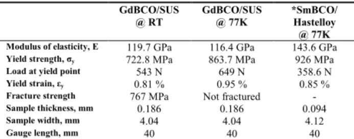
Table 2 shows the result of tensile tests both at RT and 77 K. The elastic modulus was almost the same at RT and 77 K. The yield strength of the CC tape at 77 K showed 1.2 times higher at RT which significantly increased from 723MPa to 864 MPa.
As a reference, the result of SmBCO CC tape adopting Hastelloy substrate with the same manufacturing process has been compared to the current GdBCO CC tape adopting stainless steel substrate. Fig. 2 shows the stress- strain curves of both SmBCO and GdBCO CC tapes at 77 K obtained during the I
cmeasurement at different tensile load including the result of tension test of GdBCO CC tape at RT. As can be observed from the figure, GdBCO CC tape with stainless steel substrate showed a lower elastic modulus of 115.3 GPa compared to the SmBCO CC tape with Hastelloy substrate with 143.6 GPa. In addition, SmBCO CC tape with Hastelloy substrate showed quite
higher10TABLE II
RESULTOFTHEUNIAXIALTENSIONTESTATRTAND77K. GdBCO/SUS
@ RT GdBCO/SUS
@ 77K *SmBCO/
Hastelloy
@ 77K Modulus of elasticity, E 119.7 GPa 116.4 GPa 143.6 GPa
Yield strength, σy 722.8 MPa 863.7 MPa 926 MPa
Load at yield point 543 N 649 N 358.6 N
Yield strain, εy 0.81 % 0.95 % 0.85 %
Fracture strength 767 MPa Not fractured -
Sample thickness, mm 0.186 0.186 0.094
Sample width, mm 4.04 4.04 4.12
Gauge length, mm 40 40 40
*Data of SmBCO CC tape was measured from the Ic measurement test.
0.0 0.2 0.4 0.6 0.8 1.0 1.2 1.4 1.6 1.8 2.0 0
200 400 600 800 1000
@ RTGdBCO w/ stainless steel substrate
@ 77K
SmBCO w/ hastelloy substrate GdBCO w/ stainless steel substrate
Tensile stress, MPa
Tensile strain, %
Fig. 2. Stress-strain curve of SmBCO and GdBCO CC tapes.
0.0 0.2 0.4 0.6 0.8 1.0 1.2 1.4 1.6
0.0 0.1 0.2 0.3 0.4 0.5 0.6 0.7 0.8 0.9 1.0 1.1
GdBCO-CC Tape with SUS substrate Ic0 = 167.5A εrev. = 0.73%
ε95%Ic = 0.46%
loading unloading Normalized critical current, Ic/I c0
Tensile strain, %
(a)
0 100 200 300 400 500 600 700 800 900 1000 0.3
0.4 0.5 0.6 0.7 0.8 0.9 1.0 1.1
GdBCO-CC Tape with SUS substrate Ic0 = 167.5A
σ95%Ic = 581 MPa σrev. = 812 MPa
loading unloading Normalized critical current, Ic/I c0
Tensile stress, MPa
Fig. 3. Normalized critical current as a function of (a) (b) tensile strain and (b) tensile stress in GdBCO CC tape.
higher yield strength of 926 MPa as compared to GdBCO CC tape with around 860 MPa. Fig. 3 shows the test results of the uniaxial strain/stress effect on I
cin GdBCO CC tape with stainless steel substrate. From 3(a), the I
c/I
c0decreased monotonically with strain and did not show any
I
cpeak like in the case of YBCO CC tapes [11]. During the
experiment, when the I
cdegraded about 5% at 0.46% strain
which is corresponding to the 95% I
cretention, unloading
was done to check its reversibility. The data measured at
the unloaded state were also plotted in the figure and was
connected by a dotted line. From this, the reversible strain
21
Electro-mechanical Property Evaluation of REBCO Coated Conductor Tape with Stainless Steel Substrate
limit was determined at 0.73%. Increasing further to 0.85%, the I
ccan no longer be recovered, therefore it is considered as the reversible strain limit of the current CC tape. The stress corresponding to the 95% I
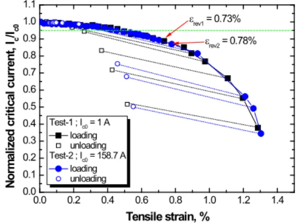
cretention was 581 MPa as can be seen in Fig. 3(b). The reversible stress limit was 812 MPa which was quite near the measured yield strength of 864 MPa in GdBCO CC tape. The reversibility test has been repeated to check the reproducibility of data using the present device and experimental procedures. In Fig. 4, the I
c/I
cocurves in test-1 and -2 conform well showing almost the same strain values corresponding to the 95% I
cretention and reversible strain limits; Reversible strain limit measured was in the range of 0.73 % to 0.78% and the corresponding stress ranges from 812 MPa to 825 MPa.
On the contrary, even though the GdBCO CC tape represented a relatively lower elastic modulus and yield strength, it showed then a higher reversible strain limit of around 0.73% compared to SmBCO CC tape with 0.56%
as can be seen in Fig. 5. It is also observed that in a short sample with 40 mm gauge length, the SmBCO CC tapes with Hastelloy substrate showed an abrupt decrease in I
cafter the reversible limit. This can be attributed to the discontinuous yielding of Hastelloy substrate which may result from the local stress concentration due to occurrence
0.0 0.2 0.4 0.6 0.8 1.0 1.2 1.4
0.0 0.1 0.2 0.3 0.4 0.5 0.6 0.7 0.8 0.9 1.0 1.1
εrev2 = 0.78%
εrev1 = 0.73%
Test-1 ; Ic0 = 1 A loading unloading Test-2 ; Ic0 = 158.7 A
loading unloading
Normalized critical current, Ic/Ic0
Tensile strain, %
Fig. 4. Normalized critical current as a function of tensile strain in GdBCO CC tape.
0.0 0.2 0.4 0.6 0.8 1.0 1.2 1.4
0.0 0.2 0.4 0.6 0.8 1.0
εrev. = 0.73%
SmBCO CC with hastelloy substrate
loading unloading
GdBCO CC with stainless steel substrate
loading unloading Normalized critical current, Ic/Ic0
Tensile strain, % εrev. = 0.56%
Fig. 5. Normalized critical current as a function of (a) tensile strain and (b) tensile stress in GdBCO CC tape.
of Luder’s bands [12]. But in the case of GdBCO with stainless substrate, even after the reversible strain limit, the I
cdegraded monotonically representing a homogeneous deformation within the gauge length thus showing a continuous yielding of the substrate as can be observed from the stress-strain curve in Fig. 2.
It should be noted that the samples evaluated here are currently under development and are nearly reaching to commercialization. By adopting stainless steel substrate, mechanical strength and electromechanical properties comparable to when Hastelloy substrate is adopted could be achieved. A clear understanding on the mechanical response of the composite conductors should be obtained to design a CC tape that can withstand a larger mechanical stress/strain during manufacturing and operation. Further investigation on the microscopic response of these materials is necessary to ensure a safe performance of the CC tapes in operating conditions.
Finally, to evaluate quantitatively the effect of substrate material on the I
c-ε
tbehavior, it should be considered comparing CC tapes with the same superconducting coating film.
4. CONCLUSION
The GdBCO CC tape with stainless substrate showed relatively good mechanical and electro-mechanical properties under uniaxial tension. Strain tolerance limits of I
care comparable and superior with those CC tapes adopting Hastelloy substrate. Although the I
cshowed a good uniaxial strain tolerance in GdBCO CC tapes, further evaluation of its electromechanical properties under other loading mode such as bending, torsion and fatigue should be done including its response under magnetic field.
ACKNOWLEDGMENT
This work was supported by a Grant from the Center for Applied Superconductivity Technology under the DAPAS (Development of Advance Power System by Applied Superconductivity Technology) Program funded by the Ministry of Education, Science and Technology, Republic of Korea.
REFERENCES
[1] V. Selvamanickam, Y. Chen, X. Xiong, YY Xie, M. Martchevski, A.
Rar, Y. Qiao, R. Schmidt, A. Knoll, K. Lenseth, CS Weber, “High performance 2G wires: fron R&D to pilot-scale manufacturing,”
IEEE Trans. Appl. Supercond., vol. 19, no. 3, pp. 3225-3230, 2009.
[2] D. W. Hazelton, V. Selvamanickam, J. M. Duval, D. C. Larbalestier, W. D. Markiewicz, H. W. Weijers, RL Holtz, “Recent development in 2G HTS coil technology,” IEEE Trans. Appl. Supercond., vol. 19, no. 3, pp. 2218-2222, 2009.
[3] H. W. Weijers, U. P. Trociewitz, W. D. Markiewicz, J. Jiang, D.
Myers, E. E. Hellstrom, A. Xu, J. Jaroszynski, P. Noyes, Y.
Viouchkov, D. C. Larbalestier, “High field magnets with HTS conductors,” IEEE Trans. Appl. Supercond., vol. 20, no. 3, pp.
576-582, 2010.
[4] M. Ohya, Y. Ashibe, M. Watanabe, T. Minamino, H. Yumura, T.
Masuda, T. Kato, “Development of RE-123 superconducting cable,” IEEE Trans. Appl. Supercond., vol. 19, no. 3, pp. 176-1769, 2009.
22
M. J. Dedicatoria, H. S. Shin, H. S. Ha, S. S. Oh, S. H. Moon
[5] H. M. Tang, D. L. Kim, Y. S. Choi, B. S. Lee, H. S. Yang, Y. S. Kim,
“Inductances of a superconducting magnet for cyclotron K120,”
KIASC Journal, vol. 10, no. 4, pp. 29-32, 2008.
[6] N. Fujiwara, H. Hayashi, S. Nagaya, Y. Shiohara, “Development of YBCO power devices in Japan,” Physica C, vol. 470, pp. 980-985, 2010.
[7] H. S. Yang, D. L. Kim, S. H. Sohn, J. H. Lim, H. O. Choi, Y. S. Choi, B. S. Lee, W. M. Jung, H. S. Ryoo, S. D. Hwang, ‘Long term performance test of KEPCO HTS power cable,” IEEE Trans. Appl.
Supercond., vol. 19, no. 3, pp. 1782-1784, 2009.
[8] K. Watanabe, S. Awaji, G. Nishijima, T. Kiyoshi, H. Kumakura, S.
Hanai, K. Koyanagi, M. Ono, “20 T compact superconducting outsert employing Y123 coated conductors for a 45 T hybrid magnet,” IEEE Trans. Appl. Supercond., vol. 19, no. 3, pp.
1592-1595, 2009.
[9] B. S. Lee, K. C. Chung, S. M. Lim, H. J. Kim, D. Youm, C. Park,
“Fabrication of Sm1Ba2Cu3O7 coated conductors using the co-evaporation method,” Supercond. Sci. Tech., vol. 372-376, p 880, 2004.
[10] H. S. Kim, H. S. Ha, T. H. Kim, J. S. Yang, R. K. Ko, K. J. Song, D.
W. Ha, N. J. Lee, S. S. Oh, D. J. Youm, C. Park, The deposition of Sm1Ba2Cu3O7 on SrTiO3 using co-evaporation method,” Physica C, vol. 460-462, pp. 1361-1362, 2007.
[11] H. S. Shin, K. H. Kim, J. R. C. Dizon, T. Y. Kim, R. K. Ko, S. S. Oh,
“The strain effect on critical current in YBCO coated conductors with different stabilizing layer,” Supercond. Sci. Tech., vol. 18, no.
12, pp. S364-S368, Dec. 2005.
[12] M. Sugano, K. Osamura, W. Prusseit, K. Itoh, T. Kiyoshi, “Tensile fracture behavior of RE-123 coated conductors induced by discontinuous yielding in Hastelloy C-276 substrate,” Supercond.
Sci. Tech., vol. 18, no. 12, pp. S344-S350, Dec. 2005.